

Biomolecular Sensing Processing and Analysis - Rashid Bashir and Steve Wereley
.pdf238 |
J. AURA GIMM AND DAVID J. BEEBE |
FIGURE 11.14. Electrically responsive hydrogel under low DC voltage (anode is on right side). The change in color is due to change in pH. As time progresses (c is after 960 seconds after), a low pH front diffuses away from the anode allowing change of the pH indicator [8].
Present limitations include asymmetric swelling and bubble formation at electrodes. However, improved electrode materials and designs should mitigate these limitations. The volume change is controlled by varying the duty cycle of the pulse width and the volume change occurs within seconds of changing the duty cycle.
The ability to finely tune the volume of the hydrogel with an electric field opens the door to electrically controllable valves and micropumps for flow control in microsystems; further broadening the potential uses of hydrogels in microfluidics. A device could be made to vary the fluidic resistance of a microchannel through modulation of the hydrogel volume with an electric field. If the hydrogel were positioned on a flexible membrane above a second channel, as described in a previous section, the flow could be regulated through pulse width modulation. The time response of electrically stimulated hydrogels is superior (seconds) to chemically stimulated hydrogels (minutes) (for similar diffusion distances). The reason for the improved time response is complex and is described elsewhere.
11.3.15.1. Systems Integration The previous sections examined design and fabrication of individual microfluidic components that were able to function in an autonomous manner due to the utilization of responsive materials. Now, to realize a microsystem capable of performing a complete assay, the components must be integrated to allow the various analytical process steps within the assay to be performed sequentially in an autonomous and continuous manner. To accommodate for the variation in the sequence of the process steps between assays, µFT provides the end-user with the flexibility to design and fabricate the microsystem on an ad-hoc basis. Moreover, the connectivity between the analytical processes can be improved by incorporating a decision mechanism, wherein an end or by-product of a preceding process activates subsequent component or process. For example, a physical wall separating two reagents can be ‘dissolved’ by the end product of a preceding reaction step, thus initiating the next step of the assay. Furthermore, since the components are in situ fabricated, the integration process is a part of the design and fabrication processes. Therefore, the tasks for development of a microsystem is reduced to designing the layout of the components, choosing appropriate materials, and fabrication of the components via liquid phase photopolymerization or laminar flow method; all of which can be performed by the end-user. However, since most of the components are created from monomer solutions and require solvents to remove unpolymerized materials, compatibility between polymerized structures and monomer solutions of the next component to be fabricated (or solvent) must be addressed. By judiciously choosing the sequence in which the components are fabricated, such compatibility issues can be averted. Additionally, temporary valves / walls (e.g. virtual wall)
MICROFLUIDIC TECTONICS |
239 |
can be included in the design layout to separate polymerized components from monomer or solvent.
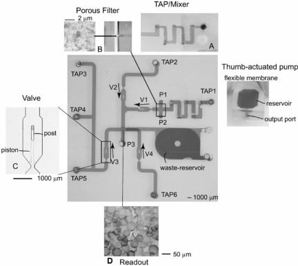
As an initial step towards integration of microfluidic components, a biochemical signal transduction detection system (refer to earlier section on detection via signal transfer) was fabricated. A porous filter was used to trap liposomes while a dissolvable hydrogel was used as the readout. To minimize fabrication issues the components were created in the following order—channel network, hydrogel readout and filter. Presently, we are developing an integrated microsystem that can perform sample preparation (dilution and separation of serum) and detection of a bioagent via ELISA (Enzyme Linked Immunoassay). The various components include reservoir, chaotic mixer, check-valves, filter and a detection unit. A detail description of the integrated ELISA device is published elsewhere (Moorthy, Submitted).
The ease and versatility of liquid phase micro fabrication facilitates the creation of microstructured devices using low cost materials and equipment. The ability to add multiple layers without bonding allows for added geometry and increases the functional density. The multilayer technique provides a method of interconnecting layers or combining separate layers to form a truly integrated multilayered microfluidic device. Because this method is based on the fundamentals of µFT, all components (valves, mixers, filters) compatible with µFT can be integrated into multilayer channel networks. An example of multilayered devices is shown in Figure 11.15.
FIGURE 11.15. Layout of an integrated device composed of mixer (a), filter (b), valve (c), and readout (d) [59].
240 |
J. AURA GIMM AND DAVID J. BEEBE |
11.4. CONCLUDING REMARKS
There are many approaches to designing and fabricating microsystems and the choice of approach will ultimately depend upon the specific requirements of the end application. In this chapter, we have described a technology platform and design approach called microfluidic tectonics. The approach utilizes liquid phase photopolymerization to create all the components required to perform many microfluidic operations. The methods are very rapid and easy to implement with a minimum investment in equipment. The all organic approach eliminates the need for external power in some applications. Because a set of common fabrication methods is used to make all the components, the integration of multiple components is straightforward. Finally, the use of stimuli responsive materials allows for autonomous operation.
REFERENCES
[1]J.R. Anderson, D.T. Chiu, R.J. Jackman, O. Cherniavskaya, J.C. McDonald, H.K. Wu, S.H. Whitesides, and G.M. Whitesides. Anal. Chem., 72(14):3158–3164, 2000.
[2]R.C. Anderson, G.J. Bogdan, Z. Bamiv, T.D. Dawes, J. Winkler, and K. Roy. Proceedings of International Solid State Sensors and Actuators Conference (Transducers ’97), 16–19 June 1997, IEEE, Chicago, IL, USA, 477–480, 1997.
[3]H. Andersson, W. van derWijngaart, P. Nilsson, P. Enoksson, and G. Stemme. Sens. Actu. B-Chem., 72(3):259– 265, 2001.
[4]J. Atencia and D.J. Beebe. Micro Total Analysis Systems. Kluwer Academics, Squaw Valley, USA, 883–886, 2003.
[5]G.D. Aumiller, E.A. Chandross, W.J. Tomlinson, and H.P. Weber. J. Appl. Phys., 45(10):4557–4562, 1974.
[6]M. Barbic, J.J. Mock, A.P. Gray, and S. Schultz. Appl. Phys. Lett., 79(9):1399–1401, 2001.
[7]R.L. Bardell, N.R. Sharma, F.K. Forster, M.A. Afromowitz, and R.J. Penney. Proceedings of the 1997 ASME International Mechanical Engineering Congress and Exposition, Nov 16–21, 1997, ASME, Fairfield, NJ, USA, Dallas, TX, USA, pp. 47–53, 1997.
[8]M.J. Bassetti, A.N. Chatterjee, N.R. Aluru, and D.J. Beebe. J. Microelectomech. Sys., in press.
[9]H. Becker and C. Gartner. Electrophoresis, 21(1):12–26, 2000.
[10]H. Becker, U. Heim, and O. Roetting. Proceedings of SPIE—The International Society for Optical Engineering, pp. 74–79, 1999.
[11]D.J. Beebe, J.S. Moore, Q. Yu, R.H. Liu, M.L. Kraft, B.H. Jo, and C. Devadoss. Proc. Natl. Acad. Sci. USA, 97(25):13488–13493, 2000.
[12]K.D. Belfield, K.J. Schafer, Y.U. Liu, J. Liu, X.B. Ren, and E.W. Van Stryland. J. Phys. Org. Chem., 13(12):837–849, 2000.
[13]W.L. Benard, H. Kahn, A.H. Heuer, and M.A. Huff. J. Microelectromech. Sys., 7(2):245–251, 1998.
[14]G. Bernstein, H. Goodson, and G. Snier. Fabrication technoloiges for nanoelectromechanical systems. The MEMS Handbook. M. Gad-el-Hak, New York, CRC, Vol. 36, pp. 1–24, 2002.
[15]S. Bohm, W. Olthuis, and P. Bergveld. Sens. Actu. A-Phys., 77(3):223–228, 1999.
[16]M. Capanu, J.G. Boyd, and P.J. Hesketh. J. Microelectromech. Sys., 9(2):181–189, 2000.
[17]W. Chang, D. Tzebotich, L.P. Lee, and D. Liepmann. 1st Annual International IEEE-EMBS Special Topic Conference on Microtechnologies in Medicine and Biology. Proceedings. 12–14 Oct. 2000, IEEE, Lyon, France, 311–315, 2000.
[18]J. Choi, S. Kim, R. Trichur, H. Cho et al. Micro Total Analysis Systems, Kluwer Academics, Boston, USA, pp. 411–412, 2001.
[19]V. Dolnik, S.R. Liu, and S. Jovanovich. Electrophoresis, 21(1):41–54, 2000.
[20]D.C. Duffy, J.C. McDonald, O.J.A. Schueller, and G.M. Whitesides. Anal. Chem., 70(23):4974–4984, 1998.
[21]D.T. Eddington, R.H. Liu, J.S. Moore, and D.J. Beebe. Lab on a Chip, 1(2):96–99, 2001.
MICROFLUIDIC TECTONICS |
241 |
[22]C. Effenhauser, H. Harttig, and P. Kramer. Micro Total Analysis Systems, Kluwer Academics, Boston, USA, 397–398, 2001.
[23]D. Figeys and D. Pinto. Anal. Chem., 72(9):330a–335a, 2000.
[24]X. Geng, H. Yuan, H.N. Oguz, and A. Prosperetti. J. Micromech. Microeng., 11(3):270–276, 2001.
[25]J.A. Gimm, A.E. Ruoho, and D.J. Beebe. Micro Total Analysis Systems, Kluwer Academics, Nara, Japan, 922–924, 2002.
[26]A. Hatch, A.E. Kamholz, G. Holman, P. Yager, and K.F. Bohringer. J. Microelectromech. Sys., 10(2):215–221, 2001.
[27]M. Heckele, W. Bacher, and K.D. Muller. Microsys. Technol., 4(3):122–124, 1998.
[28]C. Heller. Electrophoresis, 22(4):629–643, 2001.
[29]A.C. Henry, E.A. Waddell, R. Shreiner, and L.E. Locascio. Electrophoresis, 23(5):791–798, 2002.
[30]A.S. Hoffman. Adv. Drug Deliv. Rev., 54(1):3–12, 2002.
[31]R.J. Jackman, S.T. Brittain, A. Adams, H.K. Wu, M.G. Prentiss, S. Whitesides, and G.M. Whitesides. Langmuir, 15(3):826–836, 1999.
[32]W.C. Jackson, T.A. Bennett, B.S. Edwards, E. Prossnitz, G.P. Lopez, and L.A. Sklar. Biotech. 33(1):220–226, 2002.
[33]W.C. Jackson, H.D. Tran, M.J. O’Brien, E. Rabinovich, and G.P. Lopez. J. Vacul. Sci. Technol. B, 19(2):596– 599, 2001.
[34]R.W. Jaszewski, H. Schift, J. Gobrecht, and P. Smith. Microelectron. Eng., 42:575–578, 1998.
[35]N.L. Jeon, S.K.W. Dertinger, D.T. Chiu, I.S. Choi, A.D. Stroock, and G.M. Whitesides. Langmuir, 16(22):8311–8316, 2000.
[36]B.H. Jo, L.M. Van Lerberghe, K.M. Motsegood, and D.J. Beebe. J. Microelectromech. Sys., 9(1):76–81, 2000.
[37]T.J. Johnson, D. Ross, M. Gaitan, and L.E. Locascio. Anal. Chem., 73(15):3656–3661, 2001a.
[38]T.J. Johnson, E.A. Waddell, G.W. Kramer, and L.E. Locascio. Appl. Sur. Sci., 181(1–2):149–159, 2001b.
[39]V.W. Jones, J.R. Kenseth, M.D. Porter, C.L. Mosher, and E. Henderson. Anal. Chem., 70(7):1233–1241, 1998.
[40]A. Kakuta, F.G. Bessoth, and A. Manz. Chem. Rec., 1(5):395–405, 2001.
[41]M. Khoo and C. Liu. Sens. Actu. A-Phys., 89(3):259–266, 2001.
[42]C. Khoury, G.A. Mensing, and D.J. Beebe. Lab on a Chip, 2(1):50–55, 2002.
[43]D. Kim and D.J. Beebe. Micro Total Analysis Systems, Kluwer Academics, Squaw Valley, USA, 527–530, 2003.
[44]M.L. Kraft and J.S. Moore. J. Am. Chem. Soc., 123(51):12921–12922, 2001.
[45]A.V. Lemoff and A.P. Lee. Sens. Actu. B (Chemical), B63(3):178–185, 2000.
[46]R.H. Liu, M.A. Stremler, K.V. Sharp, M.G. Olsen, J.G. Santiago, R.J. Adrian, H. Aref, and D.J. Beebe. J. Microelectromech. Sys., 9(2):190–197, 2000.
[47]R.H. Liu, Q. Yu, and D.J. Beebe. J. Microelectromech. Sys., 11(1):45–53, 2002.
[48]L.H. Lu, K.S. Ryu, and C. Liu. J. Microelectromech. Sys., 11(5):462–469, 2002.
[49]M. Madou. MEMS fabrication. The MEMS Handbook. M. Gad-el-Hak, New York, CRC, Vol. 16, pp. 1–183, 2002.
[50]L. Martynova, L.E. Locascio, M. Gaitan, G.W. Kramer, R.G. Christensen, and W.A. MacCrehan. Anal. Chem., 69(23):4783–4789, 1997.
[51]S. Masuda, M. Washizu, and T. Nanba. IEEE Trans. Ind. Appl., 25(4):732–737, 1989.
[52]J.C. McDonald, D.C. Duffy, J.R. Anderson, D.T. Chiu, H.K. Wu, O.J.A. Schueller, and G.M. Whitesides. Electrophoresis, 21(1):27–40, 2000.
[53]G. Mensing, T. Pearce, and D.J. Beebe. 2nd Annual International IEEE-EMB Special Topic Conference on Microtechnologies in Medicine & Biology, pp. 531–534, 2002.
[54]G. Mensing, T. Pearce, M. Graham, and D.J. Beebe. Philosoph. Trans.: Math., Phys., and Eng. Sci., 362(1818):1059–1068, 2004.
[55]G. Mensing, T. Pearce, and D.J. Beebe. J. Assoc. Lab Automat., 10:24–28, 2005.
[56]T. Miyata, T. Uragami, and K. Nakamae. Adv. Drug Deliv. Rev., 54(1):79–98, 2002.
[57]J. Moorthy and D.J. Beebe. Lab on a Chip, 2(2):76–80, 2002.
[58]J. Moorthy and D.J. Beebe. Lab on a Chip, 3(2):62–66, 2003.
[59]J. Moorthy, G.A. Mensing, D. Kim, S. Mohanty, D.T. Eddington, W.H. Tepp, E.A. Johnson, and D.J. Beebe. Electrophoresis, 25:1705–1713, 2004.
242 |
J. AURA GIMM AND DAVID J. BEEBE |
[60]M. Ornelas-Rodriguez, S. Calixto, Y.L. Sheng, and C. Turck. Appl. Optics., 41(22):4590–4595, 2002.
[61]Y. Osada and S.B. Ross-Murphy. Sci. Am., 268:82–87, 1993.
[62]R. Perez-Castillejos, J. Esteve, M. Acero, and J. Plaza. Micro Total Analysis Systems, Kluwer Academics, Boston, USA, 492–494, 2001.
[63]E.C. Peters, M. Petro, F. Svec, and J.M.J. Frechet. Anal. Chem., 69(17):3646–3649, 1997.
[64]E.C. Peters, M. Petro, F. Svec, and J.M.J. Frechet. Anal. Chem., 70(11):2288–2295, 1998.
[65]D.S. Peterson, T. Rohr, F. Svec, and J.M.J. Frechet. Anal. Chem., 74(16):4081–4088, 2002.
[66]R. Pethig, J.P.H. Burt, A. Parton, N. Rizvi, M.S. Talary, and J.A. Tame. J. Micromech. Microeng., 8(2):57–63, 1998.
[67]N.A. Polson and M.A. Hayes. Anal. Chem., 73(11):312a–319a, 2001.
[68]S.R. Quake and A. Scherer. Science, 290(5496):1536–1540, 2000.
[69]J. Rehm, T. Shepodd, and E. Hesselbrink. Micro Total Analysis Systems, Kluwer Academics, Boston, 227– 227, 2001
[70]M.A. Roberts, J.S. Rossier, P. Bercier, and H. Girault. Anal. Chem., 69(11):2035–2042, 1997.
[71]H. Schift, C. David, M. Gabriel, J. Gobrecht, L.J. Heyderman, W. Kaiser, S. Koppel, and L. Scandella. Microelectron. Eng., 53(1–4):171–174, 2000.
[72]I. Simdikova, A. Kueper, I. Sbarski, E. Harvey, and J.P. Hayes. Proceedings of SPIE—The International Society for Optical Engineering, pp. 82–92, 2002.
[73]Y.-C. Su, L. Lin, A.P. Pisano. Proceedings of the IEEE Micro Electro Mechanical Systems (MEMS), Vol. 393, 2001.
[74]M.A. Unger, H.P. Chou, T. Thorsen, A. Scherer, and S.R. Quake. Science, 288(5463):113–116, 2000.
[75]G.M. Walker and D.J. Beebe. Lab on a Chip, 2(3):131–134, 2002.
[76]A. Wego and L. Pagel. Sens. Actu. A-Phys., 88(3):220–226, 2001.
[77]G.M. Whitesides, E. Ostuni, S. Takayama, X.Y. Jiang, and D.E. Ingber. Ann. Rev. Biomed. Eng., 3:335–373, 2001.
[78]C. Yu, M.H. Davey, F. Svec, and J.M.J. Frechet. Anal. Chem., 73(21):5088–5096, 2001a.
[79]Q. Yu, J.M. Bauer, J.S. Moore, and D.J. Beebe. Appl. Phys. Lett., 78(17):2589–2591, 2001b.
[80]Q. Yu, J.S. Moore, and D.J. Beebe. Micro Total Analysis Systems, Kluwer Academics, Nara, Japan, 712–714, 2002.
[81]B. Zhao, J.S. Moore, and D.J. Beebe. Science, 291(5506):1023–1026, 2001.
[82]B. Zhao, J.S. Moore, and D.J. Beebe. Anal. Chem., 74(16):4259–4268, 2002.
12
AC Electrokinetic Stirring and
Focusing of Nanoparticles
Marin Sigurdson, Dong-Eui Chang, Idan Tuval,
Igor Mezic, and Carl Meinhart
Department of Mechanical Engineering, University of California—Santa Barbara
12.1. INTRODUCTION
Immunoassay-based sensors rely on specific antigen-antibody binding for identification of proteins. These sensors have applications in both clinical laboratories for medical diagnostics, and in research laboratories for highly-multiplexed testing. In these cases, throughput is a key consideration. One factor limiting test duration is diffusion of analyte to the reporter. An incubation step of minutes to hours is required for diffusion-limited reactions to reach detectable levels. These tests are usually performed at centralized labs where high throughput is achieved through robotics and highly parallel assays. However, if the assay could be moved from a centralized lab to the point of care, the test could be much faster, as well as smaller, while maintaining high sensitivity.
In response to this need, microfluidic assays for diagnostics have developed dramatically in recent years. This facilitates the use of the lab-on-a-chip concepts for point-of-care diagnosis, and high throughput screening for molecular diagnostics. The small length scales associated with microfluidic devices permit small sample sizes and shorter assay incubation times. In addition, on-chip sample preparation reduces fluid handling steps. Though greatly aided by their small length scales, these assays can still be diffusion limited. Ac electrokinetic stirring can potentially reduce incubation times, and can be adaptable to a wide variety of assay configurations.
244 |
MARIN SIGURDSON ET AL. |
12.2. AC ELECTROKINETIC PHENOMENA
Ac electrokinetics refers to induced particle or fluid motion resulting from externally applied ac electric fields. Dc electrokinetics has been widely successful for lab-on-a-chip applications such as capillary zone electrophoresis (Aclara and Caliper [1, 5], capillary gel electrophoresis for DNA fractionation [19] and electroosmotic pumping [3, 4]. However, ac electrokinetics has received relatively little attention. Ac electrokinetics have the advantages over its dc counterpart by (1) largely avoiding electrolysis, and (2) operating at relatively lower voltages (1 20 V). Ac electrokinetics can be classified into three broad areas: dielectrophoresis (DEP), electrothermal flow, and AC electro-osmosis [18].
Dielectrophoresis is a force arising from differences in polarizability between the particle and the fluid medium in the presence of a non-uniform electric field. DEP has been used to separate blood cells and to capture DNA molecules [7, 12, 21, 23, 24], provides an overview). However, since the force scales with the cube of particle radius, it has limited effectiveness for manipulating nanoscale molecules (such as 10 nm-scale antigen).
AC Electroosmosis arises when the tangential component of the electric field interacts with a field-induced double layer along a surface. It becomes less important for sufficiently large electric field frequencies. For example, in an aqueous saline solution with an electrical conductivity of σ = 2 × 10⁻³ S/m, it is predicted that AC electroosmosis is not important above 100 kHz [17].
Transport enhancement for small proteins may be most successful through electrothermally driven flow (ETF). A non-uniform electric field produces non-uniform Joule heating of the fluid, which gives rise to spatial variations in electrical conductivity and permittivity. These variations create electrical charge density variations, even for electrically neutral fluids. The electrical charge density coupled with the applied electric field gives rise to Coulomb body forces in the fluid. The Coulomb body forces induce local fluid stirring. These characteristic swirling flow patterns can be used to transport suspended molecules towards a heterogeneous binding region, or for non-local focusing of particles away from the electrode surface. This can increase the binding rate of immuno-assays, and therefore can improve the response time and overall sensitivity of microfluidic-based sensors.
12.3. DEP: A SYSTEM THEORY APPROACH
If a dielectric particle is suspended in an ac electric field, acting within a dielectric medium, it will polarize. The magnitude and direction of the induced dipole will depend on the frequency and the magnitude of the applied electric field and the dielectric properties of the particle and the medium. A nonhomogeneous electric field acting on the induced dipole in turn produces a force on the dipole, called the dielectrophoretic (DEP) force. Thus, dielectrophoresis is the force exerted on a particle in the presence of a non-uniform electric field [16] (see Fig. 12.1).
To explain this in more detail we describe a systems theory of dielectrophoresis, as developed in Chang et al. 2003. The induced dipole moment, m(q, t ), in a particle due to an external electric field, E(q, t ), depends linearly on the electric field [6, 10]. This linear

AC ELECTROKINETIC STIRRING AND FOCUSING OF NANOPARTICLES |
245 |
FIGURE 12.1. Particles suspended in a nonhomogeneous ac electric field experience a force due to the interaction of the induced dipole moment and the applied electric field. In a) force due to magnitude gradient is represented. In b) force due to phase gradient of the electric field is shown (figure from [9]).
relation can be written as |
|
|
mˆ |
ˆ |
(12.1) |
(q, s) = G(s)E(q, s), |
where mˆ |
ˆ |
(q, s), E(q, s) are the Laplace transforms of m(q, t ), E(q, t ), respectively, and G(s) |
is the transfer function. When a spherical particle with the permittivity εp , the conductivity σp and radius r, lies in a medium with the permittivity εm and the conductivity σm , the transfer function G(s) is given by
|
|
|
|
|
|
σp |
|
|
|
σm |
|
|
|
||||
G(s) 4πr m |
p |
+σ |
|
|
|
− |
|
m |
+ |
σm |
(12.2) |
||||||
p |
|
||||||||||||||||
= |
3 |
|
|
|
|
s |
|
|
|
|
|
|
s |
|
|
|
|
|
p + |
|
|
+ 2 m + |
|
, |
|
||||||||||
|
s |
s |
|
||||||||||||||
where G(s)/(4πr.3εm) is the so-called Clausius-Mossotti function [10, 78]. Notice that the transfer function depends on the electric properties both of the particle and of the medium. The dielectrophoretic force, Fdep , on the particle due to the interaction between the induced dipole and the electric field, is given by
Fdep(q, t ) = (m(q, t ) · )E(q, t )., |
(12.3) |
||||
The time-averaged force, Fdep , is defined by |
|
|
|
||
|
dep (q) = T →∞ T |
0 |
T |
|
|
Fdep(q, t )dt |
|
||||
F |
1 |
|
|
|
|
lim |
|
|
|
(12.4) |
|
|
|
|
|||
246 |
MARIN SIGURDSON ET AL. |
assuming this limit exists. These equations give the relationship between the electric field and the resultant dielectrophoretic force on particles.
We illustrate this formalism with the computation of dielectrophoretic forces corresponding to various (curl-free) electric fields; similar computations can be used to compute DEP forces of various geometries and time-dependencies. We will consider the following four cases:
Case 1. The electric field is:
|
|
E(q, t ) = E1(q) cos(ωt ) |
(12.5) |
Giving: |
|
|
|
m(q, t ) = |G( j ω)| cos(ωt + G( j ω))E1(q), |
|
||
Fdep(q, t ) = |
1 |
|G( j ω)| cos(ωt + G( j ω)) cos(ωt ) |E1(q)|2, |
|
2 |
|
||
Fdep (q) = |
1 |
Re[G( j ω)] |E1(q)|2· |
(12.6) |
|
|||
4 |
|||
Notice that Fdep moves particles toward the maxima of the magnitude of the electric field if Re[G(jω)] > 0, see Fig. 12.1. The maxima of the magnitude of electric fields usually occur at the edge of electrodes. This is known as positive DEP or p-DEP. Negative DEP occurs when the DEP force is away from intense electric fields, and is denoted by n-DEP.
Case 2. The electric field is periodic with period T > 0 as: |
|
|
|
||||||||||||||||||||
|
|
|
|
|
|
|
|
|
|
|
|
|
E(q, t ) = E(q, t + T ) |
|
|
|
(12.7) |
||||||
Here, we can express the electric field as a Fourier series: |
|
|
|
|
|||||||||||||||||||
|
|
|
|
|
|
|
|
|
∞ |
c |
|
|
|
|
|
|
s |
|
|
|
|
|
|
E(q, t ) = E0(q) + n=1 |
(En |
(q) cos(nωt ) + En (q) sin(nωt )). |
|
|
(12.8) |
||||||||||||||||||
Then, |
|
|
|
|
|
|
|
|
|
|
|
|
|
|
|
|
|
|
|
|
|
|
|
|
|
|
|
|
1 |
|
|
|
|
|
|
|
|
|
∞ |
1 |
|
|
|
|
|
||
Fdep (q) = |
|
|
|
G(0) |E0|2 + |
|
|
Re[G( j nω)] (|Enc |2 + |Ens |2) |
|
|||||||||||||||
|
2 |
n=1 |
2 |
|
|||||||||||||||||||
|
|
|
|
|
|
|
|
∞ |
1 |
|
|
|
|
|
|
|
|
|
|
|
|||
|
|
|
|
|
|
|
|
|
|
|
|
|
|
|
|
|
|
|
|
|
|||
|
|
|
|
|
|
|
Im[G( j nω)] × (Enc × Ens ). |
|
|
|
(12.9) |
||||||||||||
|
|
|
|
+ |
n=2 |
2 |
|
|
|
||||||||||||||
|
|
|
|
|
|
|
|
|
|
|
|
|
|
|
|
|
|
|
|
|
|
|
|
Writing the periodic field in the following form |
|
|
|
|
|
||||||||||||||||||
E(q, t ) = E0,y (q) |
+ |
|
|
|
|
En,y (q) cos(nωt + φn,y (q)) |
, |
(12.10) |
|||||||||||||||
|
|
|
|
|
E0,x (q) |
∞ |
|
En,x (q) cos(nωt |
+ φn,x (q)) |
|
|
|
|||||||||||
|
|
|
|
|
|
|
|
|
|
|
|
|
|
|
+ |
φn,z (q)) |
|
|
|||||
|
|
|
|
|
E0,z (q) |
n=1 |
|
En,z (q) cos(nωt |
|
|
|
|
|||||||||||
we obtain the following form of the averaged dielectrophoretic force: |
|
|
|||||||||||||||||||||
|
1 |
|
|
|
|
|
|
|
∞ |
|
1 |
|
|
|
|
|
|
|
|
||||
|
|
|
|
|
|
|
|
|
|
|
|
|
|
|
|
|
|
|
|
|
|
|
|
Fdep (q) = |
|
2 |
G(0) |E0|2 + |
|
|
4 |
Re[G( j nω)] (En2,x + En2,y + En2,z ) |
|
|||||||||||||||
|
|
|
∞ |
|
1 |
|
|
|
n=1 |
|
|
|
|
|
|
|
|
|
|
|
|||
|
|
|
|
Im[G( j nω)](En2,x φn,x + En2,y φn,y + En2,z φn,z ). |
|
||||||||||||||||||
|
|
|
|
|
(12.11) |
||||||||||||||||||
|
+ |
|
|
2 |
|||||||||||||||||||
|
|
|
n=1 |
|
|
|
|
|
|
|
|
|
|
|
|
|
|
|
|
|
|
|
|
AC ELECTROKINETIC STIRRING AND FOCUSING OF NANOPARTICLES |
247 |
In dielectrophoresis literature, the time-dependence of the force is typically sinusoidal. However, it is sometimes convenient to use non-sinusoidal periodic signals such as square waves, saw-tooth waves, to achieve a desired effect. The formulas above allow us to compute the corresponding time-averaged force. Notice that the electric field is not only periodic but also traveling. In addition, the dielectrophoretic force depends on the imaginary part of the transfer function and the gradient of the phases. This results in traveling wave DEP, or tw-DEP, illustrated in Fig. 12.1b.
Case 3. An almost-periodic electric field of the form:
∞ |
c |
s |
(q) sin(ωn t )) |
|
E(q, t ) = E0(q) + n=1 |
(En |
(q) cos(ωn t ) + En |
(12.12) |
where all the nonzero ωn are distinct. The averaged dielectric force is given by
|
1 |
|
|
∞ |
1 |
|
||
|
|
|
|
|
|
|
|
|
Fdep (q) = |
|
2 |
G(0) |E0|2 + |
4 |
Re[G( j ωn )] (|Enc |2|Ens |2) |
|
||
|
|
|
∞ |
|
n=1 |
|
|
|
|
|
|
1 |
|
|
|
||
|
|
|
Im[G( j ωn )] × (Enc × Enc ). |
(12.13) |
||||
|
+ |
2 |
||||||
|
|
|
n=1 |
|
|
|
|
|
Case 4. A general time-varying electric field E(q,t):
The corresponding dielectric force can be written in a compact form as follows:
t
Fdep(q, t ) = g(t − τ )(E(q, τ ) · )E(q, t )dτ (12.14)
0
where g(t) is the impulse response of the dipole system, G(s).
12.4. NON-LOCAL DEP TRAPPING
The above theory is valid when the fluid flow is negligible. However, if ac electrokinetically-induce fluid flow (such as electrothermal or ac electroosmotic flow) is present, it can induce both desirable and undesirable effects. In the case of n-DEP, particles can be trapped close to the electrodes, instead of being induced away from the electrodes. In the case of p-DEP, it may not be desirable for particles to collect at the electrodes.
By utilizing carefully the effects of electrokinetically-induced fluid motion, one can focus particles at a non-local region away from the electrode surfaces using p-DEP, leading to orders of magnitude increase in local concentration of particles. Here, we discuss the theory behind this focusing phenomenon, based on the work in [20].
As described in the previous sections, an electric field can induce fluid motion through an electrothermal force. Experimental evidence, as well as full numerical simulations, show convective rolls centered at the electrode edges [11, 18, 22]. The fluid velocity ranges from 1-100 µm/s, with an exponential decay as we move away from the electrodes. The boundary conditions are: no-slip at the bottom of the device, and both the horizontal component of the velocity and the normal derivative of the vertical velocity are zero at the symmetry planes.