

John Wiley & Sons - 2004 - Analysis of Genes and Genomes
.pdf238 CREATING MUTATIONS 7
(a) |
|
|
|
|
|
|
NH2 |
|
|
|
|
|
|
|
N |
O |
O |
S |
O |
N |
|||
|
|
||||||
|
|
|
|
|
|
|
|
HO Pg O |
Pb O |
Pa OCH2 |
|
||||
|
|
|
|
|
|
|
O |
OH |
OH |
OH |
|
||||
|
|
||||||
OH
(b)5'-CTGCAG-3' PstI Double-stranded
3'-GACGTC-5'
|
|
|
DNA cleavage |
|
5'-CTGCAG-3' PstI |
Nick in one |
|||
3'- |
GACGTC-5' |
|
strand only |
|
|
||||
5'-CTGCAG-3' PstI |
No cleavage |
|||
3'-GACGTC-5' |
|
|||
|
||||
Figure 7.3. DNA containing phosphorothioate linkages are resistant to cleavage by certain restriction enzymes. (a) The chemical structure of dCTPαS. A sulphur replaces an oxygen on the α-phosphate of the nucleotide (shown in red). (b) The effect of phosphorothioate nucleotides on DNA cleavage by the restriction enzyme PstI. PstI cleaves the sequence shown to generate four base overhanging sticky ends. If the sequence contains a phosphorothioate (indicated by the asterisk) at C residues of the recognition sequence in one strand, then the enzyme will nick the other stand only. If both strands contain a phosphorothioate, the enzyme is unable to cleave either strand
strand. The nicked DNA can be removed by treatment with exonuclease III, an enzyme that degrades DNA from its ends. The exonuclease will not degrade the mutant DNA circles since they do not have free ends. The resulting DNA is enriched for mutant circles and is transformed into E. coli. The mutation efficiency using this method can be as high as 40 –60 per cent.
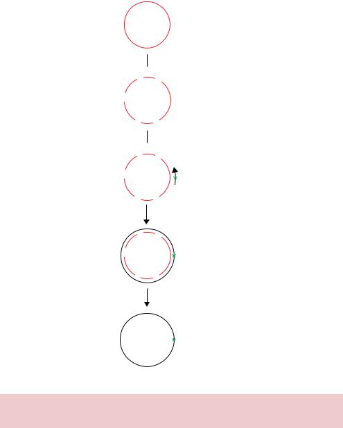
7.2.2dut− ung− (or Kunkel) Strand Selection
In this method, the non-mutated wild-type strand is targeted for degradation. The DNA template for the mutagenesis reaction is obtained from phage grown in E. coli cells that contain mutations in both the dut and ung genes (Figure 7.4).
7.2 STRAND SELECTION METHODS |
239 |
|
|
Recombinant
M13 DNA
Transfect into dut- ung- E. coli. Recover viral  particles, extract ssDNA
UU
U
UU
Anneal mutagenic
 oligonucleotide
UU
U
UU
Synthesise second
DNA strand
UU
U
UU
Transfect into wild-type E. coli
Parental strand destroyed
Mutagenised strand replicated
Figure 7.4. The dut− ung− strand selection method (Kunkel, 1985) to degrade nonmutant sequences during site directed mutagenesis. See the text for details
•The dut gene encodes dUTPase whose function is to degrade dUTP within the cell. The dut mutation results in an elevated concentration of dUTP accumulating within the cell and results in incorporation of uracil (U) in place thymine (T) at some positions during DNA replication.
•The ung gene encodes uracil N-glycosylase, which normally removes uracil from DNA.

240 CREATING MUTATIONS 7
Thus, in a double mutant (dut−, ung−) uracil is incorporated into DNA and this error is not repaired. U residues have the same base pairing properties as T, so the incorporation of U into DNA in place of T is not mutagenic in itself. M13 phage DNA isolated from a dut− ung− E. coli strain will contain approximately 20 –30 U residues per 8000 bases of its genome. The isolated single-stranded M13 DNA is used as a template for the annealing of mutagenic oligonucleotide. The extension reaction is preformed as described above to generate a newly synthesized mutant DNA strand that does not contain uracil residues. Again, after synthesis of the second DNA strand is complete, the ends are covalently joined using DNA ligase. The resulting double-stranded DNA consists of the wild-type strand that contains uracil residues, and the newly synthesized strand that contains the mutant bases present in the oligonucleotide but no uracil residues. The double-stranded DNA is then transformed into ung+ wild-type E. coli cells, where the uracil N-glycosylase recognizes the uracil residues in the DNA, and excises the uracil base to leave apyrimidinic sites in the template strand. The presence of apyrimidinic sites makes the DNA strand biologically inactive because it cannot be replicated by DNA polymerase. The DNA is cut at the apyrimidinic sites by a specific nuclease (endonuclease IV) within the E. coli cell and degraded. Hence, when the double-stranded DNA is introduced into the ung+ E. coli, only the mutant strand will be replicated. Using this approach, mutation efficiencies approaching 100 per cent can be obtained.
Although high DNA mutation efficiencies can be obtained using the methods described above, all of these techniques rely on the initial cloning of the gene to be mutated into an M13 phage so that single-stranded DNA can be isolated. The widespread use of double-stranded plasmid DNA as vectors makes the cloning of DNA fragments into an M13 mutagenesis vector, and the subsequent re-cloning of the mutated DNA back into the original plasmid, a time-consuming process.
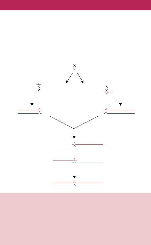
7.3Cassette Mutagenesis
Cassette mutagenesis relies on the presence of two restriction enzyme recognition sites flanking the DNA that is to be mutated (Figure 7.5). The plasmid is cut with the enzymes and the large DNA fragment representing the majority of the plasmid is purified from the smaller fragment. The linear plasmid DNA is then ligated to a synthetic double-stranded DNA produced through the annealing of two complementary oligonucleotides (Figure 7.5). The complementary oligonucleotides contain the desired mutation(s) and the required overhanging sequences for the ligation to the restriction enzyme cleavage sites (Wells, Vasser and Powers, 1985). This procedure is highly efficient at producing
|
|
|
|
|
|
|
|
|
7.4 |
PCR BASED MUTAGENESIS |
241 |
|||||||||
|
|
|
|
|
|
|
|
|
|
|
|
|
|
|
|
|
|
|
|
|
1/1 |
|
EcoRI |
|
|
28/10 |
PstI |
|
|
|
|
|
|
|
|||||||
|
|
|
|
|
|
5'-ATG |
CTG AAT TCT ATC GAA CAA GCA TGC |
GAT ATT |
TGC CTG CAG AAA-3' |
|
|
|
|
|
||||||
|
|
|
|
|
|
3'-TAC |
GAC TTA AGA TAG CTT |
GTT CGT ACG |
CTA TAA |
ACG GAC GTC TTT-5' |
|
|
|
|
|
|
||||
|
|
|
|
|
|
M |
L |
N S I E |
Q A C |
D |
I |
C L Q K |
|
|
|
|
|
|||
|
|
|
|
|
|
|
|
|
|
|
|
|
|
|
|
|
|
|||
|
|
|
|
|
|
|
|
|
|
|
|
|
|
|
|
|
|
|
|
|
|
|
|
|
|
|
|
|
|
|
Cut with EcoRI and PstI |
|
|
|
|
|
|
|
|||
|
|
|
|
|
|
|
|
|
|
|
|
|
|
|
|
|
||||
|
|
|
|
|
|
|
|
|
|
|
||||||||||
|
|
|
5'-ATG CTG |
|
AAT TCT ATC GAA CAA GCA TGC GAT ATT TGC CTG CA |
G AAA-3' |
|
|
|
|||||||||||
|
|
|
3'-TAC GAC TTA A |
GA TAG CTT GTT CGT ACG CTA TAA ACG G |
AC GTC TTT-5' |
|
|
|
||||||||||||
|
|
|
|
|
|
|
|
|
|
|
|
|
|
|
|
|
|
|
|
|
|
|
|
|
|
|
|
|
|
|
|
|
|
|
|
|
|
|
|
|
|
Synthesise two complementary oligonucleotides
5'-AAT TCT ATC GAA CAA AAA TGC GAT ATT TGC CTG CA-3' 3'-GA TAG CTT GTT TTT ACG CTA TAA ACG G-5'
|
|
|
|
Liagte cassette to |
||
|
|
|
|
cut plasmid |
||
1/1 |
28/10 |
|
|
|||
|
|
5'-ATG CTG AAT |
TCT ATC GAA CAA AAA TGC GAT ATT TGC CTG CAG AAA-3' |
|
||
|
|
3'-TAC GAC TTA |
AGA TAG CTT GTT TTT ACG CTA TAA ACG GAC GTC TTT-5' |
|
|
|
|
|
M L N |
S I E Q K C D I C L Q K |
|
||
|
|
|
|
|
|
|
|
|
|
|
|
|
|
Figure 7.5. Cassette mutagenesis. The DNA flanked by two restriction enzyme recognition sites is cleaved from a plasmid DNA and replaced with a double-stranded oligonucleotide cassette that contains the required mutation. Here, an alanine (A) codon in the protein coding sequence between the EcoRI and PstI cleavage sites is altered to a lysine (K) codon. The single-stranded oligonucleotides are synthesized such that, when hybridized, they will form the required sticky ends for ligation to the cut plasmid DNA
mutations, provided that the small wild-type DNA fragment can be eliminated. The technique does, however, suffer from a major drawback in that it requires two restriction enzyme recognition sequences to flank the DNA that is to be mutated (Worrall, 1994). Oligonucleotides are difficult to synthesize accurately above about 70 nucleotides in length. Although this is not the limit at which that the restriction sites can be separated, since multiple overlapping oligonucleotides can be synthesized to produce larger sequence, it does present a barrier to the physical size of a cassette that can be produced effectively. We will return to cassette mutagenesis again when we look at the production of random mutations in specific genes.
7.4PCR Based Mutagenesis
We have already seen how, by suitable design of oligonucleotide primers, mutations can be introduced into the ends of PCR products in a way that leads to mutagenesis efficiency of almost 100 per cent (Chapter 4). This method (see Figure 4.7), in which mutations are introduced within the PCR primers
242 CREATING MUTATIONS 7
themselves, is an immensely powerful tool for introducing DNA alterations into the ends of linear DNA fragments, but is limited to those ends. PCR protocols have, however, been developed to enable the creation of mutation at any point throughout the length of the PCR product (Higuchi, Krummel and Saiki, 1988). This method, often referred to as two-step PCR mutagenesis, requires four oligonucleotide primers and three separate PCR reactions and is outlined in Figure 7.6. Two of the primers (1 and 4) are designed to be complementary
|
|
|
|
|
|
|
5′ |
|
|
|
|
|
|
|
|
3′ |
|
|
|
|
|
|
|
|
|
|
|
|
|
|
|
|
|
|
|
|
|
|
|
|
|
|
|
|
|
|
|||
|
|
|
|
|
|
|
3′ |
|
|
|
|
|
|
|
|
|
5′ |
|
|
|
|
|
|
|
|
|
|
|
|
|
|
|
|
Reaction 1 |
|
|
|
Reaction 2 |
|
|
|
|
|
|
|
|
|||
|
|
|
|
|
|
|
|
|
|
|
|
|
|
|
|
|
|
|
|
|
|
|||
|
|
|
|
|
Primer 2 |
|
|
|
|
|
|
|
|
|
|
|
|
|
Primer 4 |
|||||
5′ |
|
|
|
3′ |
5′ |
|
|
|
|
3′ |
|
5′ |
|
|
|
|
|
3′ |
|
5 |
′3′ |
|||
|
|
|
|
|
|
|
|
|
|
|
|
|
|
|||||||||||
|
|
|
|
|
|
|
|
|
|
|
|
|
|
|
|
|
|
|||||||
3′ |
|
|
|
|
|
|
|
|
|
5′ |
|
3′ |
|
|
|
|
|
|
|
|
|
5′ |
||
5′ |
|
3′ |
|
|
|
|
|
|
|
|
|
5′ |
3′ |
|
|
|
||||||||
|
|
|
|
|
|
|
|
|
|
|
|
|
|
|
|
|
||||||||
|
|
Primer 1 |
|
|
|
|
|
|
|
|
|
|
|
Primer 3 |
|
|
|
|
|
|
||||
|
|
|
|
|
|
PCR amplify using either primers 1&2 or primers 3&4 |
|
|
|
|
|
|
|
|||||||||||
|
|
5′ |
|
|
|
3′ |
|
|
|
|
|
|
|
|
|
5′ |
|
|
|
|
3′ |
|||
|
|
3′ |
|
|
|
5′ |
|
|
|
|
|
|
|
|
|
3′ |
|
|
|
|
5′ |
|||
|
|
|
|
|
|
|
|
|
|
|
|
|
Mix and denature |
|
|
|
|
|
|
|
||||
|
|
|
|
|
|
|
|
|
|
|
|
|
Allow to rehybridise |
|
|
|
|
|
|
|
||||
|
|
|
|
|
|
|
|
|
3′ |
5′ |
|
5′ |
3′ |
|
|
|
|
|
|
|
||||
|
|
|
|
|
|
|
|
|
|
|
|
|
|
|
|
|
|
|
|
|
||||
|
|
|
|
|
|
|
|
|
|
Cannot be extended |
|
|
|
|
|
|
|
|
|
|||||
|
|
|
|
|
|
|
|
|
|
|
|
+ |
|
|
|
|
|
|
|
|
|
|
|
|
|
|
|
|
|
|
|
|
|
5′ |
3′ |
|
3′ |
5′ |
|
|
|
|
|
|
|
||||
|
|
|
|
|
|
|
|
|
|
|
|
|
|
|
|
|
|
|
|
|
||||
|
|
|
|
|
|
|
|
|
|
|
|
|
Extend with DNA polymerase, then |
|
|
|
|
|
||||||
|
|
|
|
|
|
|
|
|
|
|
|
|
|
|
|
|
|
|||||||
|
|
|
|
|
|
|
|
|
|
|
|
|
PCR amplify with primers 1&4 |
|
|
|
|
|
||||||
|
|
|
|
|
|
|
|
|
5′ |
|
|
|
|
|
|
3′ |
|
|
|
|
|
|
|
|
|
|
|
|
|
|
|
|
|
|
|
|
|
|
|
|
|
|
|
|
|
|
|||
|
|
|
|
|
|
|
|
|
3′ |
|
|
|
|
|
|
5′ |
|
|
|
|
|
|
|
|
Figure 7.6. Two-step PCR to introduce mutations into the middle of an amplified DNA fragment. Overlapping primers (primer 2 and primer 3) are designed to introduce a mutation onto a newly synthesized antisense or sense strand, respectively. These primers are used in separate PCR experiments to amplify the required DNA fragment in two sections – the DNA containing the mutation and sequences at the 5 -end of the sense strand and, separately, the DNA containing the mutation and sequences at the 3 -end of the sense strand. The two PCR products formed by this process can anneal to each other through their complementary sequences, as dictated by the position of primers 2 and 3. The mixed DNA strands can then be amplified using primers 1 and 4 to generate the intact DNA fragment that now contains the mutation
7.4 PCR BASED MUTAGENESIS |
243 |
|
|
to the anti-sense strand and the sense strand of the target DNA, respectively. The other two primers (2 and 3) are designed to bind to the different strands of the same DNA sequence and will also introduce the required mutation into each strand. In the first PCR, the 5 -end of the gene is amplified using primers 1 and 2. The resulting product will bear the mutation at its 3 -end. In the second PCR, the 3 -end of the gene is amplified using primers 3 and 4 so that the resulting product will bear the mutation at its 5 -end. Primers 2 and 3 are designed such that they are complementary to each other and overlap with one another. This means that the 3 -end of PCR product 1 will be identical to the 5 -end of PCR product 2. Therefore, if PCR products 1 and 2 are mixed with each other, denatured and allowed to cool, then the individual strands from each reaction can hybridize with each other. Two possible hybrid molecules can form. If the sense strand of PCR 2 binds to the antisense strand of PCR 1, then a molecule is produced that cannot be extended using DNA polymerase (the 3 -ends are not base paired). However, if the sense strand of PCR 1 binds to the antisense strand of PCR 2, then DNA polymerase can produce a double-stranded version of the gene that contains the mutation. In practice, the products of PCR 1 and PCR 2 are mixed in the presence of primers 1 and 4 so that the full-length mutant gene is amplified to yield large quantities of the mutant DNA. In Figure 7.6, primers 1 and 4 are shown as not introducing mutations into the gene. It is often the case, however, that these primers are used to introduce restriction enzyme recognition sites into the PCR product (as illustrated in Figure 4.7) so that the mutant gene may be readily cloned into a plasmid.
The mutagenesis efficiency of PCR methods is very high. The amplification steps ensure that practically no wild-type DNA will be present in the final product. There are, however, several drawbacks to the method.
•The error-prone nature of certain thermostable DNA polymerases means that other, unwanted, mutations may be introduced into the mutant product. It is therefore essential that the entire PCR product be sequenced (see Chapter 9) to ensure that the correct mutation has been made while others have not.
•Large DNA fragments are difficult to amplify using PCR. This may limit the size of the final amplified product that can be successfully produced.
The ability to introduce mutations at will within a segment of DNA has allowed many exceptionally elegant and precise gene analyses to be performed that would have not been previously been possible. Additionally, the initial treatment of the mutagenesis reaction as two separate components means

244 CREATING MUTATIONS 7
that the technique can readily be adapted to the creation of chimeric DNA sequences. There are a variety of reasons why particular DNA sequences may need to be joined together.
•Deletion analysis – the removal of certain gene sequences can be viewed as the fusion of the remaining sequences to each other.
•Changing the promoter of a gene to express it differently – as we will see in Chapter 8, many genes are expressed in foreign host cells to maximize protein production. So that foreign genes are expressed, they invariably need to be placed under the control of a host promoter sequence.
•Construction of novel genes – new proteins may be produced by the fusion of DNA sequences encoding portions of different genes; e.g. proteins may be tagged with certain sequences to allow their simple purification, or to direct them to certain cellular locations by the addition of signal sequences.
Traditional cloning methods to fuse DNA sequences together rely on the presence of restriction enzyme recognition sites to allow the insertion of foreign DNA. This limits the types of fusion that can be produced and the level of precision to which a particular fusion can be made. Using a PCR based approach can, however, completely alleviate these problems. Suitable PCR primer design, as illustrated in Figure 7.6, will lead to the precise fusion of any two DNA sequences if the ends of the primers contain overlapping sequences. That is, primers (2 and 3 in Figure 7.6) are designed such that they overlap with each other and contain the final fusion junction within their sequence. Thus, the joining of the two initial PCR products together will result in the formation of a precise fusion as dictated by the sequence of the primers in the first reactions.
A specific example, taken from my own work (Reece and Ptashne, 1993), where two-step PCR has been used to great effect to create gene fusions, is shown in Figure 7.7. The yeast Saccharomyces cerevisiae contains a large family of sequence related transcription factors called the C6 zinc cluster proteins. Like the majority of eukaryotic transcription factors, these proteins each have a separate DNA binding domain and an activation domain – whose function is to target the protein to particular genes, and recruit RNA polymerase II, respectively. The DNA binding domains of three of these proteins, Gal4p, Put3p and Ppr1p, is located at the amino-terminal end of each protein, and each contains six highly conserved cysteine residues that chelate two zinc ions to form the functional DNA binding domain (DBD). Each protein binds as a homodimer to its respective DNA binding site. The DNA binding sites of these three proteins are also related to each other (Figure 7.7(b)). That is, each site
|
|
|
|
|
|
|
|
|
|
7.4 |
|
PCR BASED MUTAGENESIS |
245 |
|||||||||||||||||
|
|
|
|
|
|
|
|
|
|
|
|
|
|
|
|
|
|
|
|
|
|
|
|
|
|
|
|
|
|
|
(a) |
|
|
|
|
|
|
|
|
|
|
|
|
|
|
|
|
C6 zinc cluster |
|
|
|
|
|
|
|||||||
Gal4p: |
|
|
|
|
1 |
|
10 |
|
|
|
|
20 |
|
|
|
|
30 |
|
|
|
|
|
40 |
|
|
|||||
|
|
|
|
|
|
|
|
|
MKLLSSIEQACDICRLKKLKCSKEKPKCAKCLKNNWECRY |
|
|
|
|
- |
|
|||||||||||||||
Put3p: |
1 |
10 |
|
20 |
30 |
|
|
|
|
40 |
50 |
|
|
|
|
|
60 |
|
|
|
||||||||||
MVTDQGSRHSIQSKQPAYVNKQPQKRQQRSSVACLSCRKRHIKCPGGNP- |
CQKCVTSNAICEY |
|
- |
|
||||||||||||||||||||||||||
Ppr1p: |
1 |
10 |
|
20 |
30 |
|
|
|
|
40 |
50 |
|
|
|
|
60 |
|
|
|
|
|
|||||||||
MKQKKFNSKKSNRTDLSKRGDSPNIGISKSRTACKRCRLKKIKCDQEFPSCKRCAKLEVPCVS |
|
|
|
- |
|
|||||||||||||||||||||||||
|
|
|
|
Linker |
|
|
|
Dimerization |
|
|
|
|
|
|
|
|
|
|
|
|
|
|
|
|
|
|
|
|||
Gal4p: |
|
50 |
|
|
|
|
60 |
70 |
|
|
80 |
|
90 |
|
|
|
100 |
|
|
|||||||||||
|
|
- |
|
|
|
|||||||||||||||||||||||||
|
|
|
|
|
|
|
|
|
|
|||||||||||||||||||||
|
SPKTKRSPLTRAHLTEVESRLERLEQLFLLIFPREDLDMILKMDSLQDIKALLTGLFVQD |
|
|
|
|
|||||||||||||||||||||||||
Put3p: |
- |
70 |
|
|
|
|
80 |
90 |
|
|
|
|
100 |
|
110 |
|
|
|
|
120 |
|
|
|
|
|
|||||
LEPSKKIVVSTKYLQQLQKDLNDKTEENNRLKALLLERPVSVRGKDNSDDDERHINNAPSSDTL |
|
|||||||||||||||||||||||||||||
Ppr1p: |
|
|
70 |
|
|
|
80 |
90 |
|
|
|
|
100 |
110 |
|
|
|
|
120 |
|
|
|
|
|
||||||
- |
|
LDPATGKDVPRSYVFFLEDRLAVMMRVLKEYGVDPTKIRGNIPATSDDEPFDLKKYSSVS |
|
|||||||||||||||||||||||||||
(b) |
|
|
|
|
|
|
|
|
|
|
|
|
|
|
|
|
|
|
|
|
|
|
|
|
|
|
|
|
|
|
|
Gal4p: |
5'-CGG AGGACAGTCCT CCG-3' |
|
|
|
|
|
|
|
|
|
|
|
|
|
|
|
|
||||||||||||
|
|
|
3'-GCC TCCTGTCAGGA GGC-5' |
|
|
|
|
|
|
|
|
|
|
|
|
|
|
|
|
|||||||||||
|
|
Put3p: |
5'-CGG GAAGCCAACT CCG-3' |
|
|
|
|
|
|
|
|
|
|
|
|
|
|
|
|
|||||||||||
|
|
|
3'-GCC CTTCGGTTGA GGC-5' |
|
|
|
|
|
|
|
|
|
|
|
|
|
|
|
|
|||||||||||
|
|
Ppr1p: |
5'-CGG NRNTYN CCG-3' |
|
|
|
|
|
|
|
|
|
|
|
|
|
|
|
|
|||||||||||
|
|
|
3'-GCC NYNARN GGC-5' |
|
|
|
|
|
|
|
|
|
|
|
|
|
|
|
|
|||||||||||
(c) Gal4p: |
|
40 |
50 |
|
60 |
70 |
|
|
|
|
80 |
90 |
|
|
|
|
100 |
|
|
|
||||||||||
WECRYSPKTKRSPLTRAHLTEVESRLERLEQLFLLIFPREDLDMILKMDSLQDIKALLTGLFVQD |
|
|||||||||||||||||||||||||||||
|
WECEYLEPSKKIVVSTKYLQQLQKDLNDKTEENNRLKALLLERPVSVRGKDNSDDDERHINNAPSSDTL |
|
||||||||||||||||||||||||||||
|
WECRYSPKTKSPSKKIVVSTKYLQQLQKDLNDKTEENNRLKALLLERPVSVRGKDNSDDDERHINNAPSSDTL |
|||||||||||||||||||||||||||||
|
WECRYSPKTKRSPLTRAHIVVSTKYLQQLQKDLNDKTEENNRLKALLLERPVSVRGKDNSDDDERHINNAPSSDTL |
|||||||||||||||||||||||||||||
|
WECRYSPKTKRSPLTRAHLTEVESRLNDKTEENNRLKALLLERPVSVRGKDNSDDDERHINNAPSSDTL |
|
||||||||||||||||||||||||||||
|
AICRYSPKTKRSPLTRAHLTEVESRLERLEQLFLLIFPREDLDMILKMDSLQDIKALLTGLFVQD |
|
||||||||||||||||||||||||||||
|
AICEYLEPLTRAHLTEVESRLERLEQLFLLIFPREDLDMILKMDSLQDIKALLTGLFVQD |
|
|
|
|
|
|
|||||||||||||||||||||||
|
AICEYLEPSKHLTRAHLTEVESRLERLEQLFLLIFPREDLDMILKMDSLQDIKALLTGLFVQD |
|
||||||||||||||||||||||||||||
|
AICEYLEPSKKLTEVESRLERLEQLFLLIFPREDLDMILKMDSLQDIKALLTGLFVQD |
|
|
|
|
|
|
|||||||||||||||||||||||
|
AICEYLEPSKKIVVSTKHLTEVESRLERLEQLFLLIFPREDLDMILKMDSLQDIKALLTGLFVQD |
|
||||||||||||||||||||||||||||
|
AICEYLEPSKKIVVSTKYLERLEQLFLLIFPREDLDMILKMDSLQDIKALLTGLFVQD |
|
|
|
|
|
|
|||||||||||||||||||||||
|
AICEYLEPSKKIVVSTKYLQQLESRLERLEQLFLLIFPREDLDMILKMDSLQDIKALLTGLFVQD |
|
||||||||||||||||||||||||||||
|
AICEYLEPSKKIVVSTKYLQQLQKDLERLEQLFLLIFPREDLDMILKMDSLQDIKALLTGLFVQD |
|
||||||||||||||||||||||||||||
Put3p: |
60 |
|
70 |
|
80 |
90 |
|
|
|
|
100 |
110 |
|
|
|
|
120 |
|
|
|
|
|
||||||||
AICEYLEPSKKIVVSTKYLQQLQKDLNDKTEENNRLKALLLERPVSVRGKDNSDDDERHINNAPSSDTL |
|
|||||||||||||||||||||||||||||
|
VPCRYSPKTKRSPLTRAHLTEVESRLERLEQLFLLIFPREDLDMILKMDSLQDIKALLTGLFVQD |
|
||||||||||||||||||||||||||||
|
VPCVSSPKTKRSPLTRAHLTEVESRLERLEQLFLLIFPREDLDMILKMDSLQDIKALLTGLFVQD |
|
||||||||||||||||||||||||||||
|
VPCVSLDPKTKRSPLTRAHLTEVESRLERLEQLFLLIFPREDLDMILKMDSLQDIKALLTGLFVQD |
|
||||||||||||||||||||||||||||
|
VPCVSLDPATGKDVPRSYVFFLESRLERLEQLFLLIFPREDLDMILKMDSLQDIKALLTGLFVQD |
|
||||||||||||||||||||||||||||
Ppr1p: |
60 |
|
70 |
|
80 |
90 |
|
|
|
|
100 |
110 |
|
|
|
|
120 |
|
|
|
|
|
||||||||
VPCVSLDPATGKDVPRSYVFFLEDRLAVMMRVLKEYGVDPTKIRGNIPATSDDEPFDLKKYSSVS |
|
|||||||||||||||||||||||||||||
Figure 7.7. The DNA binding domains of three C6 zinc cluster proteins from yeast.
(a)The amino acids sequences of the DNA binding domains of Gal4p, Put3p and Ppr1p.
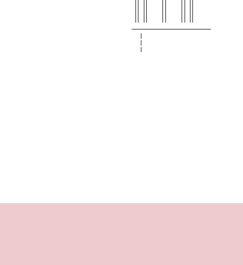
(b)The DNA binding sites for these three proteins are related in that they contain highly conserved inverted 5 -CGG-3 triplets separated by a different number of base pairs for each protein. (c) Fusion proteins produced by creating chimeric genes between GAL4, PUT3 and PPR1. The sequence of each protein is shown from just before the last cysteine residue of the C6 zinc cluster
contains highly conserved inverted 5 -CGG-3 triplet nucleotides separated by a more variable spacer. The length of the spacer is, however, different for each protein binding site. In the Gal4p binding site, the CGG triplets are separated by 11 bp, while they are separated by 10 bp in the Put3p binding site and 6 bp for Ppr1p. Since each of these related proteins is able to bind to a related, but different, DNA sequence we wanted to establish precisely which region of each protein is responsible for imparting DNA binding specificity. We therefore wanted to alter the DNA binding specificity of one C6 zinc cluster protein by replacing some of its own amino acids with the corresponding sequences from

246 CREATING MUTATIONS 7
a different C6 zinc cluster protein. In the absence of structural information we had no knowledge of where fusion junctions needed to be made that would allow functional protein production, so we created a large series of fusion proteins from DNA sequences encoding one of the C6 zinc cluster proteins that were fused to those from another (Figure 7.7(c)). Each fusion was created by two-step PCR. The location of the fusion junction was determined solely by the sequence of the oligonucleotides (2 and 3 in Figure 7.6). This allowed chimeric genes to be constructed to produce, as required, proteins in which the fusion junction could be moved amino acid by amino acid. No restriction enzyme recognition sites were required for cloning, the oligonucleotides themselves provided the overlap so that the genes could be fused. Each chimeric gene was then cloned into an E. coli expression vector and the resulting protein was purified and tested for its ability to bind to each of the DNA binding sites.
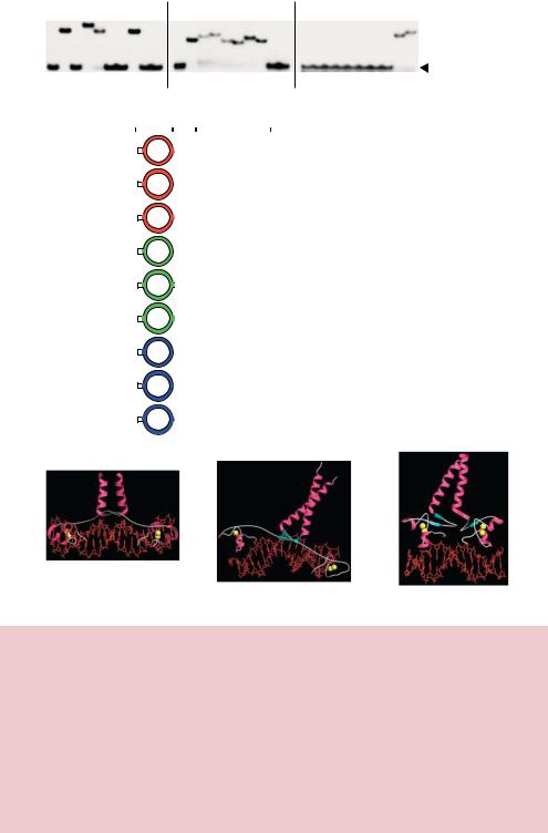
Each of the wild-type DBD proteins was found to bind to DNA with a particular specificity. Put3p and Ppr1p were found to bind to their own DNA binding site only, while Gal4p bound with high efficiency to its own site and, with approximately tenfold less efficiency, also to the Put3p binding site. Analysis of the chimeras showed that replacing the zinc cluster region (Figure 7.7(a)) of one protein with that of another had no effect on DNA binding specificity. For example, protein 4 in Figure 7.8 has the zinc cluster region of Put3p fused to the carboxy-terminal regions of Gal4p. This protein binds DNA with the specificity of Gal4p rather than Put3p. A similar type of result is noted for proteins 2 and 7. We therefore wanted to know how much sequence to the carboxy-terminal side of the zinc cluster was required to switch the DNA binding specificity to that of the zinc cluster itself. The majority of the fusions produced (Figure 7.7(c)) were unable to bind any DNA sequence, presumably due to the formation of mis-folded or incorrectly aligned protein structures. However, proteins containing the zinc cluster, and an additional 19 amino acids to its carboxy-terminal side, bound DNA with the specificity of the protein from which these sequences were derived (Figure 7.8). Thus, these 19 amino acids to the carboxy-terminal side of the zinc cluster were responsible for determining DNA binding specificity. Subsequent to this work, the structures of the Gal4p –, Put3p – and Ppr1p –DNA complexes have been solved using X-ray crystallography (Marmorstein et al., 1992; Marmorstein and Harrison, 1994; Swaminathan et al., 1997) and are shown in Figure 7.7(c)–(e). Each protein –DNA complex shows the same overall format. Each protein is dimeric and makes specific contacts with the DNA at the 5 -CGG-3 using the zinc cluster. The zinc cluster forms a compact sub-domain in which two zinc ions (yellow spheres) are bound. Extending away from the DNA is a coiled coil dimerization motif. Joining the zinc cluster to the coiled-coil is a linker region.
|
|
|
|
|
|
|
|
|
|
|
|
|
|
7.4 PCR BASED MUTAGENESIS |
247 |
||||||||
|
|
|
|
|
|
|
|
|
|
|
|
|
|
|
|
|
|
|
|
|
|
|
|
(a) |
Gal4 binding site |
|
|
Put3 binding site |
Ppr1 binding site |
|
|
||||||||||||||||
|
|
|
|
|
|||||||||||||||||||
|
|
|
|
|
|
|
|
|
|
|
|
|
|
|
|
|
|
|
|
|
DNA-protein |
|
|
|
|
|
|
|
|
|
|
|
|
|
|
|
|
|
|
|
|
|
|
|
|
|
|
|
|
|
|
|
|
|
|
|
|
|
|
|
|
|
|
|
|
|
|
|
complexes |
|
|
|
|
|
|
|
|
|
|
|
|
|
|
|
|
|
|
|
|
|
|
|
Free DNA |
|
|
|
|
|
|
|
|
|
|
|
|
|
|
|
|
|
|
|
|
|
|
|
|
|
|
|
- 1 2 3 4 5 6 7 8 9 |
|
- 1 2 3 4 5 6 7 8 9 |
- 1 2 3 4 5 6 7 8 9 |
|
|
|
|
|
|
|||||||||||||
(b) |
|
|
|
Zinc |
|
|
|
|
|
|
|
|
|
Binding |
|
|
|||||||
|
|
cluster Linker Dimerization |
|
Protein |
Specificity |
|
|
|
|||||||||||||||
|
1 |
|
|
|
Zn |
|
|
|
|
|
|
|
|
Gal4p(1−100) |
GAL4 |
|
|
||||||
|
|
|
|
|
|
|
|
|
|
|
|
|
|
||||||||||
|
|
|
|
|
|
|
|
|
|
|
|
|
|
||||||||||
|
2 |
|
|
|
Zn |
|
|
|
|
|
|
|
|
Gal4p(1−38)+ |
PUT3 |
|
|
||||||
|
|
|
|
|
|
|
|
|
|
|
|
Put3p(61−126) |
|
|
|||||||||
|
|
|
|
|
|
|
|
|
|
|
|
|
|
|
|
|
|
|
|
|
|
||
|
3 |
|
|
|
Zn |
|
|
|
|
|
|
|
Gal4p(1−61)+ |
GAL4 |
|
|
|||||||
|
|
|
|
|
|
|
|
|
|
|
Put3p(84−126) |
|
|
||||||||||
|
|
|
|
|
|
|
|
|
|
|
|
||||||||||||
|
|
|
|
|
|
|
|
|
|
|
|
|
|
|
|
|
|
|
|
|
|
||
|
4 |
|
|
|
Zn |
|
|
|
|
|
|
|
Put3p(31−60)+ |
GAL4 |
|
|
|||||||
|
|
|
|
|
|
|
|
|
|
|
|
|
|
Gal4p(39−100) |
|
|
|
|
|
|
|
|
|
|
5 |
|
|
|
Zn |
|
|
|
|
|
|
|
Put3p(31−79)+ |
PUT3 |
|
|
|||||||
|
|
|
|
|
|
|
|
|
|
|
|
|
|
Gal4p(58−100) |
|
|
|
|
|
|
|
|
|
|
|
|
|
|
|
|
|
|
|
|
|
|
|
|
|
|
|
|
|
|
|
||
|
6 |
|
|
|
Zn |
|
|
|
|
|
|
|
Put3p(31−126) |
PUT3 |
|
|
|||||||
|
7 |
|
|
|
Zn |
|
|
|
|
|
|
|
|
Ppr1p(29−63)+ |
GAL4 |
|
|
||||||
|
|
|
|
|
|
|
|
|
|
|
|
|
|
Gal4p(41−100) |
|
|
|
|
|
|
|
|
|
|
|
|
|
|
|
|
|
|
|
|
|
|
|
|
|
|
|
|
|
|
|
||
|
8 |
|
|
|
Zn |
|
|
|
|
|
|
|
Ppr1p(29−80)+ |
PPR1 |
|
|
|||||||
|
|
|
|
|
|
|
|
|
|
|
|
|
|
Gal4p(58−100) |
|
|
|
|
|
|
|
|
|
|
|
|
|
|
|
|
|
|
|
|
|
|
|
|
|
|
|
|
|
|
|
||
|
9 |
|
|
|
Zn |
|
|
|
|
|
|
|
|
Ppr1p(29−123) |
PPR1 |
|
|
||||||
|
|
|
|
|
|
|
|
|
|
|
|
|
|
||||||||||
|
|
|
|
|
|
|
|
|
|
|
|
|
|
||||||||||
(c) |
|
|
|
|
|
|
|
|
(d) |
|
|
|
|
(e) |
|
|
|
|
|||||
|
|
|
|
|
|
|
|
|
|
|
|
|
|
|
|||||||||
|
|
|
|
|
|
|
|
|
|
|
|
|
|
|
|
|
|
|
|
|
|
|
|
Gal4-DNA complex |
Put3-DNA complex |
Ppr1-DNA complex |
Figure 7.8. DNA binding activity of chimeric Gal4p, Put3p and Ppr1p. (a) Radiolabelled versions of the DNA binding sites for each protein were incubated with purified protein and then subjected to non-denaturing gel electrophoresis. The binding of the protein to the DNA retards its mobility through the gel such that it runs less far through the gel. (b) A summary of the DNA binding activity of each of the functional chimeric proteins.
(c)–(e) The structure, as determined by X-ray crystallography, of the Gal4p-DNA, Put3pDNA and Ppr1p-DNA complexes (Marmorstein et al., 1992; Marmorstein and Harrison, 1994; Swaminathan et al., 1997). In each case the DNA is depicted as a red stick model and the protein is shown as a ribbon diagram (α-helices in purple, β-sheet in blue and other polypeptide chain in white). In each model, yellow spheres represent the locations of the zinc ions