

The term on the right represents the heat loss to the walls of the atrium and ventricle. In practice, there would be an additional heat loss in the catheter. The heat loses are normally accounted for by a correction term (K) that is a function of the catheter type being used as shown below.
Q |
|
riCVi |
|
ViðTi TbÞ |
K |
¼ rbCVb |
|
||||
|
|
Z01ðTðtÞ TbÞdt |
|||
The thermal dilution method has the advantage that recirculation is not a problem due to the large surface available in the circulation to bring the injectate temperature to body temperature. A disadvantage is that the injection site and the sensing site must be close together to avoid large heat losses and the absence of total mixing in the ventricle can cause inaccuracies.
BIBLIOGRAPHY
1.Yang SS, Bentivoglio LG, Maranhao V, Goldberg H. From Cardiac Catheterization Data To Hemodynamic Parameters. 2nd ed. Philadelphia: F.A. Davis Company; 1980. p 55.
2.Geddes LA. Cardiovascular Devices and Their Applications. New York: John Wiley & Sons, Inc.; 1984. p 102–106.
3.Stewart GN. The output of the heart in dogs. Am J Physiol 1921;57:27–50.
4.Fick A. Uber die Messung des Blutstroms in den Herzventrikeln. Verhandl Phys Med Ges Zu Wurzburg 1870;2:XVI.
5.Hamilton W, et al. Comparison of the Fick and dye injection methods of measuring the cardiac output in man. Am J Physiol 153:309–321.
6.Valentinuzzi ME, Posey JA. Fast estimation of the dilution curve area by a procedure based on a compartmental hypothesis. Med Ins Sept-Oct1972;(6)5.
7.TaylorBC,Sheffer DB. Understanding TechniquesforMeasuring Cardiac Output. Biomedi Inst Technol May/June, 1990; 188–197.
8.Swinney RS, Davenport MW, Wagers P, Sebat F, Johnston W. Iced versus room temperature injectate for thermal dilution cardiac output. Ninth Annual Scientific and Educational Symposium. Soc Crit Care Med, May12–16,1980;137.
See also CARDIAC OUTPUT, FICK TECHNIQUE FOR; CARDIAC OUTPUT,
THERMODILUTION MEASUREMENT OF; ECHOCARDIOGRAPHY AND DOPPLER ECHOCARDIOGRAPHY; FLOWMETERS, ELECTROMAGNETIC; TRACER KINETICS.
CARDIAC PACEMAKER. See PACEMAKERS.
CARDIAC OUTPUT, THERMODILUTION MEASUREMENT OF
EDWIN D. TRAUTMAN
RMF Strategies
Cambridge, Massachusetts
MICHAEL N. D’AMBRA
Harvard Medical School
Cambridge, Massachusetts
INTRODUCTION
The amount of blood pumped by the heart each minute, the cardiac output, provides a measure of the body’s
CARDIAC OUTPUT, THERMODILUTION MEASUREMENT OF |
25 |
potential for supplying oxygen and nutrients and is relevant to assessing the condition of the heart. Taken together with various pressures, it is a key clinical indication of the heart’s ability to meet the body’s needs and an indirect indication of the status of those needs. In the clinical setting, measurement of cardiac output is required to guide drug therapy aimed at manipulating the function of the cardiac muscle (inotropic drugs) and the state of the systemic and pulmonary vascular resistance (vasoconstrictor and vasodilator drugs). Combined with ultrasound velocity data, cardiac output allows precise assessment of the status of mitral and aortic valve stenosis and regurgitation.
G. N. Stewart articulated the basic principle of indicatordilution measurement of cardiac output in a landmark paper in 1897 (1). Stewart stated that if a substance was introduced at a constant rate into the flowing bloodstream and allowed to mingle with the blood, then the measured steady-state concentration of that substance downstream of the site of introduction would be inversely proportional to the flow rate (cardiac output). Of greater practical importance was his additional observation that if a small amount of the substance was introduced rapidly, then the cardiac output could still be computed. To do that one would divide the average rate at which the substance is introduced (total amount divided by measurement time) by the average concentration. Stewart called this technique the ‘‘sudden injection’’ method. In the late 1920s, W. F. Hamilton and his colleagues further investigated Stewart’s sudden injection method (2,3). They found that the concentration curve from timed samples did not simply return to baseline, but exhibited a secondary rise. This was attributed to fast physiologic recirculation of an unknown amount of the indicator. To eliminate the influence of any recirculating indicator on measurement calculation, they proposed extrapolating the original down slope of concentration to zero using an exponential function. This method proved successful in validation studies both in mechanical models and animal experiments, and the sudden injection method with exponential extrapolation is commonly referred to as the Stewart–Hamilton method.
Various indicators have been used to measure cardiac output with the Stewart–Hamilton method, notably saline (detected by its effect on electrical conductivity) and optical dye (detected by its effect on optical absorption), but G. Fegler’s proposal in the mid-1950s that heat could be used has proved the most convenient, although initially controversial (4,5). His earliest report ‘‘was received with polite incredulity’’ (6). Fegler rapidly injected a small amount of cold Ringer’s solution into the vena cava and recorded the transient decrease in temperature in the aortic arch and in the right ventricle. He computed both left and right heart outputs from these data.
Concerns were voiced regarding the ability to quantify this ‘‘negative’’ indicator, the stability of the baseline temperature, and the background noise (6). These are all valid concerns, but concerns that have been successfully addressed with clinical technology. Current practice is to introduce a small bolus of cold solution into the right atrium (via a venous catheter) and to measure the

26 CARDIAC OUTPUT, THERMODILUTION MEASUREMENT OF
consequent transient temperature decrease in the pulmonary artery. With the advent of balloon-flotation pulmonary-artery pressure measurement catheterization techniques in the late 1960s (7), small thermistor sensors could be readily placed in the pulmonary artery, and the thermal dilution measurement became clinically accepted even as validation experiments progressed. The pulmonaryartery catheters provide important hemodynamic pressure information and, for that reason alone, are placed in many patients.
Swan and Ganz are credited with developing and popularizing the pulmonary-artery pressure catheter containing a thermistor and injection port for thermal dilution (8), and these catheters are commonly called Swan–Ganz catheters, although Swan–Ganz, strictly speaking, is a registered trademark of Edwards Lifesciences Corporation. The instrumentation required to process the temperature signal and determine cardiac output is modest, fitting into either a small, batteryoperated instrument easily used at the patient’s bedside, or into a module component of a bedside workstation in the ICU or operating room, making the method easy and convenient. The additional ‘‘invasion’’ of a thermistor is negligible, and the additional value of cardiac output measurements is great. And since the indicator is a physiologically innocuous solution, thermal dilution measurement of cardiac output has become an important part of clinical care. Today, bolus thermal dilution cardiac output is considered the gold standard against which other methods are compared.
THEORY
Principle of Indicator Dilution
The basic principle of indicator dilution is quite simple: If the concentration of a uniformly dispersed indicator in an unknown volume is measured, then the unknown volume can be simply determined by dividing that concentration into the total amount of indicator. If the volumeis flowing past a sensor, then the volume in any given period of time will equal the amount of indicator in that period of time divided by the concentration. If the rate at which the indicator is flowing past the sensor is controlled and known, then the amount of indicator in a period of time is also known and the volume flow rate can be determined. Alternatively, if the total amount of indicator over a larger period of time is known, such as when a bolus is introduced all at once, then average flow rates can be determined. Each approach has strengths and weaknesses in technique, necessary assumptions, and equipment. We focus on the popular bolus technique but, particularly with thermal techniques, the theory can be extended.
In the case of thermal dilution, the indicator is introduced into the right atrium and its concentration is measured in the pulmonary artery. We assume that all of the indicator introduced, an amount I, eventually passes into the pulmonary artery at some rate i(t). If we assume no indicator recirculates, we may write this
as
I ¼ Z01 iðtÞ dt |
ð1Þ |
¼ Z01 FðtÞcðtÞdt |
ð2Þ |
where F is volumetric flow and c is concentration. When the flow is constant, F can be moved out of the integral and we can solve for F as
I |
|
F ¼ R01 cðtÞdt |
(3) |
Several assumptions have been made in arriving at this equation. Equation 1 is a statement of conservation and requires that all indicators pass the sensor exactly once. Equation 2 requires that the concentration in the pulmonary artery be uniform across the area where the concentration is being measured, and equation 3 requires that the flow rate be constant. All but the first requirement can be satisfied for the pulmonary artery catheter-based measurements if we consider the right heart to be a perfect mixing chamber, with a competent valve at the outflow, and a pumping rate that is constant over the integration time. The mixing chamber guarantees that the blood will be equivalently labeled at its outflow so that each flow stream is representative of the total, and the valve guarantees that the concentration changes in a stepwise fashion in all flow streams, which allows legitimate averaging of pulsatile variations in flow. A rigorous proof can be found in Perl et al. (9) and the assumptions and necessary conditions are discussed in Trautman and Newbower (10). Each of these articles contains numerous relevant references.
Heat as an Indicator: ‘‘Thermal’’ Dilution
In thermal dilution, the indicator is caloric, introduced as a known volume of a cold physiologic solution whose concentration is measured via the induced temperature change. The relationship between temperature and the concentration of heat in a solution, the amount of heat in a unit volume, involves the specific heat and density of the solution. When two solutions at different temperatures, such as the indicator and blood, are mixed, the temperature of the mixture may be predicted by
T ¼ |
T1C p1m1 þ T2C p2m2 |
ð4Þ |
C p1m1 þ C p2m2 |
where Cp and m are, respectively, the specific heat and mass of the solutions. If we take the first solution to be the indicator solution and the second to be the blood, then the difference in temperature due to the indicator will be predicted by
ðT1 T2ÞCp1m1 |
|
T T2 ¼ C p1m1 þ C p2m2 |
(5) |
A very good assumption, at least prior to significant heat exchange with tissue, is that the indicator solution and the temperature transient travel together. In this case,

equation 5 holds for all instances of time, and the mass concentration of the indicator solution may be predicted from the temperature transient by
c t |
Þ ¼ |
½TðtÞ T2&r1 |
(6) |
|
TðtÞ T2 ðC p1r1=Cp2r2Þ½TðtÞ T1& |
||||
ð |
|
where r is the density of the solution. The amount of indicator is equal to the volume of the physiologic solution V times its density r1 (giving its mass) and equation 3 becomes
|
|
F ¼ |
Vr1 |
|
(7) |
||
|
|
R01 cðtÞ dt |
|
|
|||
F ¼ |
|
|
Vr1 |
|
(8) |
||
1 |
TðtÞ T2&r1 |
dt |
|||||
|
|
||||||
|
R0 TðtÞ T2 ð½C p1r1=Cp2r2Þ½TðtÞ T1& |
|
|
||||
Equation 8 forms the basis for the thermal dilution method for measuring cardiac output. This equation may be easily programmed, but it generally has been approximated to simplify implementation, The most common approximation is based on the assumption that the indicator solution has no effect on the thermal properties of the blood. In this case, the increment in the amount of heat leaving the heart due to the indicator is equal to
Z 1
H ¼ r2Cp2F ½TðtÞ T2&dt (9)
0
This is equivalent to equation 2 and requires the same assumptions. The amount of heat added in a certain volume of an indicator solution is equal to
H ¼ r1C p1VðT1 T2Þ |
(10) |
Equating equations 9 and 10 leads to the simpler formula for flow:
|
|
|
C |
|
|
|
F |
¼ |
|
p1r1 |
|
V½T1 T2& |
(11) |
C |
R01½TðtÞ T2&dt |
|||||
|
|
p2r2 |
|
|
Equations 8 and 11 are equivalent only when cool blood is used as the indicator. Equation 11 is simpler than equation 8 and can be implemented in an analog circuit. However, it is based on the implausible condition that the indicator solution carries heat (or cold) into the blood and then is either transported completely apart from the thermal transient or has no thermal effect on the blood. Fortunately, the practical difference between flow estimates based on these two equations is small. The ratio of thermal properties for a dextrose-in-water (D5W) indicator solution is approximately equal to 1.08, and for a normal (0.9%) saline solution it is approximately equal to 1.10. Since the expected temperature transient is 0.5–1.0 8C, the expected difference between equations 8 and 11 is only 1–2% for these indicators.
If the indicator is not introduced as a finite bolus, then the conservation statement of equations 1 and 2 needs to be generalized and other assumptions made. The product of flow rate and concentration at the outflow of the mixing chamber will still be equal to the amount of indicator
CARDIAC OUTPUT, THERMODILUTION MEASUREMENT OF |
27 |
passing by, but its relationship to the input indicator can be more complex. A simple example is where the indicator is infused at a constant rate in which case, absent recirculation, the flow rate will be inversely proportional to measured concentration. If the infusion rate is not constant then the transient response of the heart system needs to be considered.
Heat can be introduced by direct energy transfer, such as from an electrical heater. In this case, the volume factor in the numerator of equation 11 is not relevant and must be replaced by a measure of the amount of heat introduced. It is, however, impractical to introduce a large bolus (impulse) of heat comparable to the 750 W of 10 mL of iced saline: The surface temperature would be dangerously high. Instead, the heater is pulsed at low power, the resulting temperature changes measured with a fastresponse thermistor, and sophisticated signal processing used to extract the dilution signal from the baseline. Such techniques have the potential to measure cardiac output continuously and were introduced in the early 1980s (11). Catheters with heating elements (10 cm long filaments in the right ventricle) have been produced since the early 1990s (12). The surface temperature and thus the amount of heat that can be introduced are limited by physiological concerns (4–7 8C), and therefore the technique is sensitive to background thermal noise. The heater is typically pulsed, and the accuracy is dependent on processing the correlation between the heating waveform and the measured temperature response (11–13). These techniques are entering clinical use as a companion to bolus thermal dilution, but are not considered here.
Necessary Conditions
For the preceding development, we assumed that the flow is constant; the volume and temperature of the solution are known, the indicator does not recirculate, and perfect mixing occurs somewhere between injection and sampling. Little can be done to control the variation of flow; it is flow that is being measured. (In those situations where flow is not constant, it can be shown that the computed result will be a concentration-weighted average of the true cardiac output over the period of measurement.) The other assumptions are usually reasonable, although in practice it is difficult to have an accurate measure of the volume or temperature of the injected solution since heat will exchange with all material contacting the solution. There is also a lost volume in the dead space of the catheter used to introduce the solution, and it is impossible to eliminate the physiologic recirculation of indicator. In addition, the integrals must be truncated to permit a practical measurement. These and other practical issues are covered next.
Notably absent from these formulas is the time response of the thermal sensor. Although not intuitively appealing, it can be shown that this response is of little importance as long as the curve does not become distorted by the effects of noise and recirculating indicator. The area under the thermal curve is preserved even with slow-responding thermal sensors. The operator should, however, be aware that the thermal curve obtained with a slow thermistor is not necessarily a high fidelity representation of the

28 CARDIAC OUTPUT, THERMODILUTION MEASUREMENT OF
temperature transient. The observed or recorded temperature curve will be smoothed and filtered over time.
PRACTICAL APPLICATION OF THE THEORY
The practical application of thermal dilution theory is simple; all that is typically necessary to measure cardiac output is to reset the ‘‘cardiac output computer,’’ inject 2–10 mL of an icecold or room temperature solution into the catheter port, and wait for the answer to appear on the computer. The thermal sensor is contained on a special pulmonary artery catheter that also provides the injection lumen into the right atrium. The temperature curve may be recorded to reassure the operator that a reasonable signal was obtained. Typical curves for various flow rates are shown in Fig. 1.
When the computer is reset, it samples the baseline temperature, integrates the processed temperature curve until recirculation is detected or assumed, and calculates the cardiac output assuming predefined conditions. It applies a correction for the portion of the curve that is lost by the truncation of the integral (to avoid influence of recirculation). The predefined conditions include the volume and temperature of the injectate, the thermal characteristics of the fluids, and a correction factor that corrects for the physical properties of the particular injection catheter employed. Most computers make approximations and apply corrections. The most common are listed below.
Thermal Properties of Blood Are Approximately Constant
The thermal properties of blood vary with hematocrit. However, the convenience of assuming a normal hematocrit—and thus not requiring knowledge of the actual hematocrit and entering it—far outweighs the importance of the potential error. The specific heat-density product for erythrocytes is 3.52 J K 1 mL 1, and for plasma it is 4.03 J K 1 mL 1 (14). Therefore, for blood with a hematocrit of 40% this product is 3.83 J K 1 mL 1, with a hematocrit of 30% it would be 3.88 J K 1 mL 1, and with 50% it would be 3.78 J K 1 mL 1. Thus, the nominal value assumed for blood could be in error by 1–2% causing an error in the cardiac output measurement of the same value.
Indicator Does not Affect Thermal Properties of Blood
The specific heat-density product for normal (0.9%) saline is 4.19 J K 1 mL 1, and that for 5% dextrose-in-water is
|
|
3 L/min |
Temp |
0.5 °C |
5 L/min |
9 L/min |
5.0 s
Time
Figure 1. Typical thermal dilution curves, taken at different flows and superimposed to illustrate variations in shape and area.
4.11 J K 1 mL 1 (15). These are significantly different from the nominal 3.81 J K 1 mL 1 for blood. The thermal properties of the indicator-blood mixture will thus vary with the level of dilution. However, most computers assume that the indicator does not affect the thermal properties of blood. This assumption leads to the simpler equation [Eq. 11] derived above. Cardiac output computers using this approximation can be expected to overestimate the cardiac output by 1–2%.
Heat Loss Is Predictable
When the syringe containing the cold solution is taken from the ice bath it immediately begins to warm. The solution warms further as it is injected through caloric exchange with the walls of the catheter. Only a negligible amount of heat is gained during manipulation of the syringe before injection. However, the exchange with the wails of the catheter can account for several percentages with a 0 8C solution (16). In addition to those conductive losses of indicator, a significant amount of solution is left in the catheter after the injection has been terminated. The typical dead space volume is 0.9 mL so that only 91% of the solution is injected into the bloodstream. However, the solution that filled the dead space prior to injection is pushed into the blood stream and, if not at blood temperature, can add to the effective indicator volume. In addition, some of the ‘‘cold’’ left in the dead space after injection can leak through the catheter wall and add to the injectate.
Empirical studies have shown that the combination of these losses and gains can be grouped into a single correction factor, multiplying the total indicator volume. This correction factor varies only a few percentages with catheter insertion length and other mechanical factors (17). The correction factor does depend on the temperature and volume of the injected solution and on the design of the catheter. Catheter manufacturers generally provide, with their package inserts, a table of values for the correction factor or ‘‘computation constant’’ under various typical conditions. This factor is determined by measuring the average temperature of the injectate, as it emerges from the injectate, lumen of the catheter, while the appropriate length of catheter is immersed in a 37 8C bath. The amount of injectate that emerges is a reasonably constant fraction of the amount introduced.
Devices can be used to measure the temperature of the injected solution as it enters the injection catheter. This reduces the need for precisely controlling the initial temperature of the solution and reduces errors due to warming of the solution during handling. These devices do not improve knowledge about the unknown heat loss during injection. Catheters have also been fabricated with thermistors in the distal port of the injection lumen, to measure true injectate temperature. These catheters demonstrate better reproducibility particularly with room temperature injectates, but have yet to win clinical acceptance due to cost and complexity. Note also that the rate at which the indicator is introduced must be controlled and consistent to allow inferring amount of heat from temperature.

Decay of Dilution Signal Is Exponential
Recirculation of the thermal indicator is relatively small in humans since there is ample opportunity for exchange with the tissue beds. In smaller animals, recirculation is more apparent. In either case, the decay of the temperature signal measured in the pulmonary artery approximates an exponential (the result of the mixing chamber) and, once truncated, the true but obscured curve can be mathematically extrapolated with reasonable accuracy. The relatively small amount of curve area being estimated limits the significance of errors in extrapolation. Some cardiac output computers actually fit an exponential to the uncorrupted curve and use the parameters of fit to extrapolate the curve, while most assume that curves generally have the same shape and integrate to a fraction of the peak temperature and multiply this area by a constant. Either method appears to result in a reliable measure of cardiac output. Certain pathologies can alter the shape of the thermal dilution curve and reduce the effectiveness of these extrapolation procedures.
Baseline Temperature Is Constant
The baseline temperature is not constant, varying with the respiratory cycle and subject to the fluid infusions from other sources (i.e., intravenous fluid administrations). In addition, the heart itself generates heat that can be observed as very small pulsatile variations in temperature in the pulmonary artery. Fortunately, these variations and the baseline shifts are usually small compared to the 0.5– 1.0 8C dilution signal. Cardiac output computers thus assume that the baseline acquired prior to the arrival of the dilution signal remains constant during the course of the measurement. (Note that shifts in baseline can adversely affect the extrapolation procedure used to reduce the effects of recirculation.)
Flow Rate Is Constant Throughout the Integral
Cardiac output can vary by as much as 10–20% over the respiratory cycle. Since thermal dilution measurement integrals typically average only 5–10 s of the cardiac output, the measured cardiac output could vary by as much as 10–15% depending on where in the cycle the injection is made. There is really nothing the computer can do about this without information about the phases of the respiratory cycle. Cardiac arrhythmias, which can result from the cold injection, can cause dramatic errors in the measured output. The clinical practice of averaging several separate cardiac output determinations helps to average out some of the potential variation from both of these sources. See section on Measurement Performance for more discussion on accuracy and reproducibility.
EQUIPMENT
The thermal dilution method for cardiac output measurement is popular because it is easily performed with a minimum of equipment and little additional invasion of the patient. The basic equipment consists of a pulmonary artery catheter to position a thermistor or other
CARDIAC OUTPUT, THERMODILUTION MEASUREMENT OF |
29 |
temperature-sensitive element in the pulmonary artery, a means for making thermal indicator (usually saline) injections into the right atrium (usually a syringe), typically through a separate lumen in the catheter, a source of measured volumes of a cold solution, and an electronic instrument to determine the blood temperature from the thermistor signal, to determine and integrate the dilution signal, and to compute a final result. Each of these elements is described separately.
Pulmonary Artery Catheters
The pulmonary artery (PA) catheter generally contains several lumens (channels) that terminate at measured distances from the tip. A balloon, located at or near the tip, is inflated during catheter insertion to carry the tip through the heart and into the pulmonary artery (flow directed). One lumen terminates at the tip and is used to measure the pressure during catheter insertion to follow its position relative to the heart; later it measures pulmonary artery pressure and, intermittently, pulmonary capillary wedge pressure (with the balloon inflated). A second lumen typically terminates in the right atrium and is used to monitor right atrial pressure (central venous pressure). Indicator solutions are injected either through the right atrial port or through a second atrial lumen intended for drug infusion. Catheters can have several additional lumens (e.g., atrial and RV pacing wires) and sensors (e.g., mixed venous oxygen saturation). The pulmonary artery catheter provides important hemodynamic information and may be inserted in patients for that purpose alone.
For use with thermal dilution, the pulmonary artery catheter is augmented by adding a thermistor proximal to (before) the balloon (typically, 4 cm from the tip). A thermal dilution catheter is illustrated in place in Fig. 2. The
Figure 2. A pulmonary artery catheter in place in the right heart. The balloon, shown inflated here for wedge pressure measurement, normally remains deflated during pressure monitoring and cardiac output measurements. The cold injectate enters the bloodstream through the injection port, and the temperature transient is sensed by the thermistor.

30 CARDIAC OUTPUT, THERMODILUTION MEASUREMENT OF
thermistor typically is encapsulated in glass and coated with epoxy to fully insulate it electrically from the blood. The relatively slow time response of this encapsulated sensor does not affect the accuracy of the measurement since the area under a temperature curve is preserved. Wires connecting the thermistor are contained in a separate lumen. The thermistor wires terminate in an external connector that typically contains an electrical resistance used to standardize the response of the thermistor. Thus the catheter contains one-half of a Wheatstone bridge. The overall length is 100 cm, with distance marks every 10 cm to guide insertion. The typical size is 7–8.5 Fr although pediatric catheters may be 5–6 Fr. (One French is equal to one millimeter in circumference.)
Edwards Lifesciences was the original commercial manufacturer of the thermal dilution catheter, basing it on a concept acquired from Swan and Ganz, researchers involved with validation experiments. Their Swan–Ganz catheter was introduced in 1971. Since that time several manufacturers (e.g., Instrumentation Laboratories, Cobe, Abbott, Arrow) produce thermal dilution catheters, disposable items selling for $50–80 each, although catheters with heating filaments and multiple sensors can cost $200 and up. A thermal dilution catheter is shown in Fig. 3.
Pulmonary artery catheters are not without clinical complications. The threat of infection is always present. Clots can form on the poly vinyl chloride (PVC) catheter surface, but this complication has been mostly eliminated with anticoagulant coatings. Unfortunately, there are patients who have severe reaction to heparin (i.e., heparin induced thrombosis) and in these patients heparin-coated catheters need to be avoided. The catheter can become knotted in the right heart, a complication that requires a trip to the cardiac catheterization laboratory to resolve.
Most dangerous is the rare complication of the catheter tip puncturing the pulmonary artery. In normal use, the balloon is temporarily inflated, the balloon wedges into a branch of the pulmonary artery, flow through that branch of the pulmonary circulation is stopped and the pressure measured from the distal lumen will approximate the left atrial pressure. It is critical that nurses and physicians understand the waveforms associated with ‘‘permanent wedge’’ position to avoid pulmonary rupture. This complication is almost always associated with erosion of the
Figure 3. A Swan–Ganz pulmonary artery catheter produced by Edwards Lifesciences. The various lumens are accessed through individual Luer-Lok connectors fanning out from an external divider on the main catheter. The electrical connector for the thermistor wires is also connected to the main catheter at the same point. (Photograph courtesy of Edwards Lifesciences Corporation, Irvine, CA.)
pulmonary artery from a catheter permanently in the wedge position or with inflating a catheter that is in the distal pulmonary arterial position.
The balloon is an important feature of pulmonary artery catheters since it plays a key role in the acquisition of pressure information in addition to facilitating placement of the catheter. Balloons are generally made from latex and designed to inflate beyond the tip of the catheter while not occluding the distal pressure lumen. This shields the tip reducing the tip trauma to the pulmonary artery. Manufacturers attach the balloon to the base catheter in a way that minimizes rough surfaces and overall size of the catheter while being durable. Latex-free balloon catheters are available for use in patients with latex allergies, but are expensive and have limited functionality, usually having only a single right atrial port. The non-latex balloon is also not as durable and measurements of wedge pressure must be kept to a minimum.
The size and material of the catheters can vary among manufacturers and models, both of which can affect their stiffness and thus the ease of insertion, and the size of the dead space in the injection lumen and, thus, the heat loss correction factor. The injection port may be larger in some catheters, reducing injection effort. The frequency response of the pressure measurement lumens may be different due to attention to details of fluid mechanics. Personal preference, reliability, and economic concerns are also clearly important in purchase decisions. Some catheters offer other capabilities such as continuous cardiac output measurements based on advanced signal processing algorithms, mixed venous oximetry, and the ability to electrically pace right atrium and ventricle.
Cold Solution
The indicator solution is typically an isotonic saline or dextrose solution cooled to 0 8C by placing the bottle or prefilled capped syringes in an ice bath. This makes the injected indicator 37 8C cooler than body temperature. This 10 mL of 37 8C difference injected in 2 s represents extraction of thermal energy from the bloodstream at a rate of 750 W. Cold indicator is most useful in the operating room where patient temperatures can vary rapidly and dramatically. In the non-OR setting, or in operative patients where normothermia is expected, room-temperature solutions are frequently used because they are more convenient, but the variable room temperature must be monitored by the computer. The injected energy is reduced by a factor of 3, reducing the signal-to-noise ratio and, thus, expected measurement performance. Most cardiac output computers provide a temperature probe to measure the actual temperature of the bath or of the room, which is presumably the temperature of the injectate. Manufacturers also produce an optional temperature-measuring probe that attaches to the injection port on the thermal dilution catheter and measures the temperature of the injectate as it enters the catheter. This further reduces concern about the actual room or bath temperature. Some catheters also have thermistors at the injection port itself.
The ice bath is the subject of some unproved concerns regarding infection. Undesirable organisms could remain

CARDIAC OUTPUT, THERMODILUTION MEASUREMENT OF |
31 |
Figure 4. A closed injection system for cold injectate, by Edwards Lifesciences. A cooling coil rests in a Styrofoam ice bucket, the syringe serves as a piston pump to draw up a known volume of precooled injectate from the coil and to force it into the injection lumen of the catheter. The closed system reduces the risk of nosocomial contamination associated with traditional injectate delivery methods. CO-Setþ System improves reproducibility and accuracy through its in-line temperature probe and volumelimited syringe. (Photograph courtesy of Edwards Lifesciences, Irvine, CA.)
or grow in the capped syringes when left in the bath for long periods of time. A cleaner alternative to the ice bath is offered by a closed injectate system with a cooling coil, offered as an optional accessory by some manufacturers. One such device is shown in Fig. 4. The coil sits in an ice bath keeping the solution cold. The syringe is used to draw up solution and then immediately introduce it into the catheter port. Fig. 5 shows the complete system.
Although these solutions are generally benign, in some circumstances, such as in small pediatric patients, there is a risk of volume overload from frequent measurements. In these situations, smaller volumes are used (e.g., 3 mL) and fewer measurements are made.
Cardiac Output Computers
When thermal dilution measurements were first introduced in the early 1970s, manufacturers produced catheters with nonstandardized thermistors. Each manufacturer then produced a computer to mate with its catheter. In addition to generic differences in thermistor types, each individual thermistor of a given type can have a different temperature response requiring the operator to enter a calibration constant, idiosyncratic to the specific catheter, its thermistor response, and even the patient’s blood temperature. In current products, the thermistor connector contains an electrical resistance selected to match the particular thermistor and complete a half Wheatstone bridge with a standard response. The value of the resistance in this circuit is chosen such that the voltage response of the half bridge will be the same for all thermistors of a given family and also will be linear near 37 8C. The nearly linear range is 20 8C. With these catheters, the catheter is
Figure 5. Basic thermal dilution system, with computer, syringe, catheter, and source of cold injectate, in this case from a closed system. (Courtesy of Edwards Lifesciences, Irvine, CA.)
merely connected to the computer’s electronics, and the pulmonary artery blood temperature and the cardiac output can be measured. The electronic circuitry used to measure the thermal response is electrically isolated, since the thermistor is in the conductive bloodstream quite close to the heart and insulation failures can conceivably occur. Since the catheter functions as half of a Wheatstone bridge, the electronics merely mimic the other half of the bridge circuit, excite the bridge with a low level of current, and amplify the voltage difference proportional to temperature change.
When the operator signals that a measurement is to be made, the baseline temperature is acquired and the indicator concentration is computed (or approximated) and integrated. When the ‘‘end of curve’’ criterion is reached, the integration is stopped, the integral is adjusted for area lost by truncation, and the final area is inverted and multiplied by the appropriate constants for the measurement conditions. This constant is entered in the computer and only changed when conditions change. Cardiac output computers differ both in the method they use to truncate the integration and in the options they offer, such as, syringe size, injectate temperature, and integration into bedside systems.
Calibration of Equipment
Each catheter is individually calibrated by the manufacturer to give a standard response (as described previously), and the heat loss correction factor is determined also by the manufacturer for the particular catheter model for a variety of measurement conditions. No operator calibrations are necessary or practical.
In certain research settings (e.g., custom-made catheters), it is desirable to add the calibration resistor to the catheter. The value of the resistance is given by
R ¼ R0ðb 2T0Þ=ðb þ 2T0Þ |
ð12Þ |
where R0 is the thermistor resistance at 37 8C, T0 is 310 K, and b is the characteristic temperature (a gain constant) for the thermistor, equal to 3500 K for those used in thermal dilution catheters compatible with the Edwards Lifesciences standard.
32 CARDIAC OUTPUT, THERMODILUTION MEASUREMENT OF
Example Equipment
Most cardiac output computers are fully integrated into hemodynamic monitoring systems. The cardiac output component is usually part of the temperature-sensing module. Data from the measurements are acquired into the system’s data recording and analysis packages and automated calculations of systemic and pulmonary vascular resistances are obtained.
In the typical computer, the preamplifier is fully isolated and uses a conservative 7 mA to sense the thermistor resistance. When a new cardiac output is desired, the operator presses a button and rapidly injects the cold solution. The dilution curve is typically shown as it is measured and the result is displayed once the curve has finished. Analog and digital outputs may be provided for integrating into a larger measurement or workstation system. In a typical computer the temperature difference is integrated from baseline up to its peak, then down to 30% of the peak value, and multiplied by 1.22. This integral is then inverted and multiplied by the computation constant provided by the catheter manufacturer. The computation constant is the product of all constants (e.g., the ratio of thermal constants, the injectate volume, 60 s min 1, and 0.001 L mL 1) and the catheter heat-loss correction factor (e.g., 0.825). Although the method for extrapolating the integral appears overly simple, it is quite effective. As pointed out earlier, the dilution curve has a consistent shape, and amount of area obscured by recirculation is small and comes relatively late in time (in humans). Some computers use more elaborate methods.
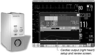
A typical computer and display is shown in Fig. 6. This example from Philips Medical Systems integrates into the monitoring system and computes several derived values as well as displaying hemodynamic information.
MEASUREMENT PERFORMANCE
Direct measurement of cardiac output is quite difficult given the location of the measurement site and the necessity
Figure 6. A modern cardiac output computer, integrated into a monitoring system, by Philips Medical Systems. The thermal dilution curve is displayed for inspection, and the cardiac indices can be automatically computed from the cardiac output and body parameters entered by the clinician. (Photograph courtesy of Philips Medical Systems, Andover, MA.)
to divert flow in some manner. The performance of thermal dilution measurements of cardiac output has been assessed in a number of less direct ways. Validation studies have been performed in mechanical flow models to assure that the measurement theory is sound in practice (and to determine the heat-loss corrections appropriate to specific catheters). Simultaneous thermal dilution and dyedilution measurements, and also thermal dilution and direct Fick measurements, have been performed in animals and humans. Comparisons have also been made with electromagnetic flowmeters in animal preparations. All of these methods have shown thermal dilution to be effective for measuring cardiac output and as accurate as these other methods. In addition, an important consideration in the clinic is the reproducibility of the measurement over time and from operator to operator. Clinical studies of this sort have shown thermal dilution to be reliable and it is now considered the gold standard against which other measurements are compared.
It is interesting to note that the dye-dilution method was the incumbent standard, using indicators, such as indocyanine green dye measured by withdrawing blood from an artery through an optical sensor. This technique measures somewhat different flows—left-heart output rather than right-heart output, for example—and is subject to other issues of physiology and technique, such as greater recirculation and accumulation of indicator. Nevertheless, dye-dilution was clinically useful and thermal dilution was shown to be better and more convenient. By the early 1980s, thermal dilution was the technique of choice.
Accuracy
The accuracy of thermal dilution is degraded by the various assumptions and approximations discussed previously. Thus, even in the absence of physiologic noise, this measurement can only be expected to be within 2–7% of the true value without other measurements and specific corrections relevant only to a research setting. This accuracy is, however, well within a clinically acceptable range and is no worse than that of other methods. In his first trials with this technique, Fegler compared thermal dilution with standard direct Fick measurements in animals, finding a discrepancy of < 7%. Early validation studies with thermal dilution catheters were performed by Ganz and colleagues in the early 1970s (8,17,18). In addition to supporting the overall accuracy of thermal dilution, they determined that the sensitivity of the result to mechanical and techniquedependent factors, such as catheter insertion length and speed of injection, was within 3%. This they considered to be biologically insignificant (17).
Others have since obtained good correlation with simultaneous dye dilution and other methods for measuring flow, if not slopes of identity. It is interesting to note that since the dye concentration is usually measured in a systemic artery, dye dilution will provide a measurement of left heart output that is 4% higher than the right heart output measured by thermal dilution, due to the bronchiolar circulation bypassing the right heart. In addition, all of these reference methods have some of their own
uncertainty in calibration, and conclusions are thus necessarily limited.
Exploration of the heat loss during injection has yielded interesting information on variability (16,19,20) but has not quantified the systematic loss to the point of accurate prediction of total injected heat (cold). The in vitro studies of effective losses and determination of correction constants provide adequate foundation for an accurate measurement.
Reproducibility
Cardiac output need not be known to great accuracy (within 10% is quite adequate) as long as the measurements are reproducible and can be used to track therapies. The reproducibility (variance) of the measurement with 10 mL of iced solution is generally accepted to be in the range of 10–15%. This is higher with room temperature solutions, and with smaller volumes (21). The reproducibility can be improved by 20–40% with a thermistor sensing the injectate temperature at the injection port in the right atrium. (20,22)
Some factors that can affect the reproducibility of this measurement derive from physiology and some from technique.
Physiology. As noted previously, the cardiac output can be expected to vary over the respiratory cycle, particularly with positive-pressure-assisted ventilation. This is shown quite succinctly in a careful study in animals by Jansen et al. (23) where the injection was made at random, but at known phases of the ventilation cycle. When plotted sequentially in time, the results span a range of 15% and appear randomly distributed. When ordered according to the phase of the ventilator, the cardiac output result varies cyclically over the course of ventilation, Therefore, a determination of cardiac output using an arbitrary injection time could differ from another determination at another arbitrary time by as much as 30% due, presumably, to real physiologic variations, with flow modulated by intrathoracic and intra-abdominal pressure. Some contribution of baseline drift and thermal noise cannot be discounted by this study.
Clinically, the baseline temperature is usually assumed to be constant during the period of the measurement. Yet blood temperature varies by as much as 0.1 8C over the ventilatory cycle due to differential blood return from the upper and lower extremities. This fluctuation in baseline temperature is typically small compared with the
1 8C thermal dilution signal obtained with 0 8C injectate, but extends over significant time. It is more significant with room temperature injectates and with heated-fila- ment (continuous cardiac output) signals. The magnitude of the baseline drift can be much greater, particularly with patient movement. Of note, intravenous fluid infusions will affect the blood temperature enormously, particularly during flushes of the lines. The heat output from the heart itself returns into the right atrium from the coronary veins in synchrony with the heartbeat. These pulsations in temperature are less pronounced, being smoothed by the mixing volume in the right ventricle, and cause little practical difficulty.
CARDIAC OUTPUT, THERMODILUTION MEASUREMENT OF |
33 |
Since the indicator is introduced immediately upstream of the heart, the solution can, conceivably, transit the heart in a single beat (or very few beats) if the ejection fraction is high. (Thermal dilution curves obtained with fast-response thermistors can be used to determine the ejection fraction by quantifying this washout time when the injection is made directly into the ventricle.) Therefore, these few beats must be representative of the average output for the measurement to be useful. An arrhythmia at the time of injection, occasionally caused by the injection, can lead to a single very large ejection with a very good ejection fraction. In this situation, the measured output will be much larger than the true average cardiac output. The method is not in error, but the measured output is not the steady-state output. Therefore, if arrhythmias are suspected, the measurement should be discarded or a very large variation in results anticipated.
Certain pathologies can affect thermal dilution cardiac output measurements. Tricuspid regurgitation will increase the effective mixing volume for the indicator, thus increasing the extent and decreasing the magnitude of the thermal transient. However, it is important to note that TR does not invalidate the fundamental physical principles upon which the measurement is based. If the computer can wait long enough, the CO measurement in the face of TR should be accurate. In order to be sure this is the case, the practitioner must watch the thermal dilution curve as it evolves on the monitor screen.
Very low ejection fractions can have a similar effect. Although the basic assumptions underlying the measurement remain intact, the curve can be distorted to an extent that makes the practical measurement unreliable. More serious problems are caused by an incompetent pulmonic valve. This valve is necessary to minimize the nonlinear averaging effects of the pulsatile flow, and any flow reversal at the thermistor can lead to multiple re-measurement of the thermal transient. Either of these effects degrades the cardiac output determination.
Technique. Thermal dilution measurements are reasonably insensitive to variations in operator technique. As noted above, the injectate will not warm significantly as the syringe is handled briefly prior to injection. And if this is a concern, probes can be used which measure the temperature of the injectate as it is injected. The content of the injection catheter dead space must be considered to achieve a high level of reproducibility. If multiple measurements are made over a short period of time, that is, to average several serial determinations, sufficient time must be allowed for the residual injectate to return to blood temperature. A couple of minutes appears sufficient to warm the dead space as well as to allow the blood temperature to return to a stable baseline. One strategy is to discard the first measurement, using it merely to fill the dead space with a cool solution. Another strategy for assuring a consistent effect from the dead space is to withdraw blood immediately following the injection. The potential for blood clotting, however, limits the applicability of this procedure. As noted earlier, some catheters can measure the temperature of the injectate at the point of injection (20,22) thus minimizing these effects.
34 CARDIAC OUTPUT, THERMODILUTION MEASUREMENT OF
In summary, judicious choice of the time of injection can improve reproducibility. Attention should be paid to the phase of ventilation, to changes in any concomitant intravenous fluid infusions, and to any concurrent cardiac arrhythmias. The temperature curve can be recorded from most cardiac output computers. This curve, and the prior baseline, can give the knowledgable operator evidence on which to judge the validity of a particular result. Recall, however, that the time course of the thermal curve is not necessarily the same as the time course of the thermal transient in the flow stream. Most clinicians use a single measurement to guide therapy although in many settings, such as in studies, it is still common practice to use the average of three serial cardiac output determinations or to discard the outlier and average the remaining two.
Ease of Use
The ease and robustness of thermal dilution measurements of cardiac output are probably responsible for its clinical popularity. The equipment is straightforward to operate, and specialized technicians are not needed to acquire reliable data. The right heart catheters may be placed for other clinical reasons without fluoroscopy. When a measurement of cardiac output is indicated, all that is necessary is to attach a computer and inject cold solution.
FUTURE DEVELOPMENTS
This measurement is simple, fundamentally inexpensive, and has remained popular for several decades. It is, however, moderately invasive. If the need for the pressure information from the pulmonary artery catheters was reduced or supplanted, the ease of making a thermal dilution measurement would diminish. There are liabilities and contraindications associated with pulmonary artery catheters and the injection of cold solutions, and this measurement is not always prescribed in critical care. Use of PA catheters is falling somewhat as other methods of assessing cardiac filling and function become more widely available, such as ultrasoundbased measurements and central venous lines. However, several million pulmonary artery catheters are used each year in North America and their widespread use is likely to continue. It is interesting that many surgeons who must manage their patients via phone consultations rely heavily on PA catheter measurements, especially when the ICU team does not include experienced physicians.
Indicator-dilution measurements of the sort described in this article are fundamentally intermittent. In many cases, a continuous measurement would be favored. Continuous cardiac output measurement with the heated filament paired with advanced signal processing is becoming popular, and other techniques such as analyzing pulse contours are also becoming more accepted. Thermal dilution with 10 mL of iced solution is the standard against which these techniques are compared, and periodically calibrated (13).
Catheters will continue to improve, with better clot resistance, materials, additional lumens, heating elements and sensing elements as measurements demand. Cardiac output is integrated into measurement systems forming
part of derived parameters and important correlations, a trend that will continue to follow medical instrumentation and healthcare information technology in general. And as the reliability of the measurements increases with experience and technology, the long-promised closed-loop therapies may become a reality.
BIBLIOGRAPHY
1.Stewart GN. Researches on the circulation time and on the influences which affect it. IV. The output of the heart. J Physiol (London) 1897;22:159–183.
2.Hamilton WF, Moore JW, Kinsman JM, Spurling RG. Simultaneous determination of the pulmonary and systemic circulation times in man and of a figure related to the cardiac output. Am J Physiol 1928;84:338–344.
3.Kinsman JM, Moore JW, Hamilton WF. Studies on the circulation. I. Injection method; physical and mathematical considerations. Am J Physiol 1929;89:322–330.
4.Fegler G. Measurement of cardiac output in anaesthetized animals by a thermo-dilution method. Q J Exp Physiol Cogn Med Sci 1954;39:153–164.
5.Fegler G. The reliability of the thermodilution method for determination of the cardiac output and the blood flow in central veins. Q J Exp Physiol Cogn Med Sci 1957;42:254–266.
6.Dow P. Estimations of cardiac output and central blood volume by dye dilution. Physiol Rev 1956;36:77–102.
7.Swan HJC et al., Catheterization of the heart with use of a flow-directed balloon-tipped catheter. N Engl J Med 1970;283: 447–451.
8.Ganz W, Swan HJ. Measurement of blood flow by thermodilution. Am J Cardiol 1972;29:241–246.
9.Perl W, Lassen NA, Effros RM. Matrix proof of flow, volume and mean transit time theorems for regional and compartmental systems. Bull Math Biol 1975;37:573–588.
10.Trautman ED, Newbower RS. The development of indicatordilution techniques. IEEE Trans Biomed Eng 1984;BME- 31:800–807.
11.Philip J et al., Continuous thermal measurement of cardiac output. IEEE Trans Biomed Eng 1984;BME-31:393–400.
12.Yelderman ML et al., Continuous thermodilution cardiac output measurement in intensive care unit patients. J Cardiothorac Vasc Anesth 1992;6:270–274.
13.Schmid ER, Schmidlin D, Tornic M, Seifert B. Continuous thermodilution cardiac output: clinical validation against a reference technique of known accuracy. Intensive Care Med 1999;25:166–172.
14.Spector WS, editor. Handbook of Biological Data. Philadelphia: Saunders; 1956; Mendlowitz M. The specific heat of human blood. Science 1948;107:97–98.
15.Diem K, editor. Documenta Geigy, Scientific Tables. Ardsley (NY): Geigy Pharmaceuticals; 1962.
16.Meisner H et al., Indicator loss during injection in the thermodilution system. Res Exp Med 1973;159:183–196.
17.Forrester JS et al., Thermodilution cardiac output determination with a single flow-directed catheter. Am Heart J 1972;83:306–311.
18.Ganz Wet al., A new technique for measurement of cardiac output by thermodilution in man. Am J Cardiol 1971;27:392–396.
19.Vliers ACAP, Visser KR, Zijlstra WG. Analysis of indicator distribution in the determination of cardiac output by thermal dilution. Cardiovasc Res 1973;7:125–132.
20.Lehmann KG, Platt MS. Improved accuracy and precision of thermodilution cardiac output measurement using a dual thermistor catheter system. J Am Coll Cardiol 1999;33:883–891.