

- •VOLUME 2
- •CONTRIBUTOR LIST
- •PREFACE
- •LIST OF ARTICLES
- •ABBREVIATIONS AND ACRONYMS
- •CONVERSION FACTORS AND UNIT SYMBOLS
- •CARBON.
- •CARDIAC CATHETERIZATION.
- •CARDIAC LIFE SUPPORT.
- •CARDIAC OUTPUT, FICK TECHNIQUE FOR
- •CARDIAC OUTPUT, INDICATOR DILUTION MEASUREMENT OF
- •CARDIAC PACEMAKER.
- •CARDIAC OUTPUT, THERMODILUTION MEASUREMENT OF
- •CARDIOPULMONARY BYPASS.
- •CARDIOPULMONARY RESUSCITATION
- •CARTILAGE AND MENISCUS, PROPERTIES OF
- •CATARACT EXTRACTION.
- •CELL COUNTER, BLOOD
- •CELLULAR IMAGING
- •CEREBROSPINAL FLUID.
- •CHEMICAL ANALYZERS.
- •CHEMICAL SHIFT IMAGING.
- •CHROMATOGRAPHY
- •CO2 ELECTRODES
- •COBALT-60 UNITS FOR RADIOTHERAPY
- •COCHLEAR PROSTHESES
- •CODES AND REGULATIONS: MEDICAL DEVICES
- •CODES AND REGULATIONS: RADIATION
- •COGNITIVE REHABILITATION.
- •COLORIMETRY
- •COMPUTERS IN CARDIOGRAPHY.
- •COLPOSCOPY
- •COMMUNICATION AIDS FOR THE BLIND.
- •COMMUNICATION DEVICES
- •COMMUNICATION DISORDERS, COMPUTER APPLICATIONS FOR
- •COMPOSITES, RESIN-BASED.
- •COMPUTED RADIOGRAPHY.
- •COMPUTED TOMOGRAPHY
- •COMPUTED TOMOGRAPHY SCREENING
- •COMPUTED TOMOGRAPHY SIMULATOR
- •COMPUTED TOMOGRAPHY, SINGLE PHOTON EMISSION
- •COMPUTER-ASSISTED DETECTION AND DIAGNOSIS
- •COMPUTERS IN CARDIOGRAPHY.
- •COMPUTERS IN THE BIOMEDICAL LABORATORY
- •COMPUTERS IN MEDICAL EDUCATION.
- •COMPUTERS IN MEDICAL RECORDS.
- •COMPUTERS IN NUCLEAR MEDICINE.
- •CONFOCAL MICROSCOPY.
- •CONFORMAL RADIOTHERAPY.
- •CONTACT LENSES
- •CONTINUOUS POSITIVE AIRWAY PRESSURE
- •CONTRACEPTIVE DEVICES
- •CORONARY ANGIOPLASTY AND GUIDEWIRE DIAGNOSTICS
- •CRYOSURGERY
- •CRYOTHERAPY.
- •CT SCAN.
- •CUTANEOUS BLOOD FLOW, DOPPLER MEASUREMENT OF
- •CYSTIC FIBROSIS SWEAT TEST
- •CYTOLOGY, AUTOMATED
- •DECAY, RADIOACTIVE.
- •DECOMPRESSION SICKNESS, TREATMENT.
- •DEFIBRILLATORS
- •DENTISTRY, BIOMATERIALS FOR.
- •DIATHERMY, SURGICAL.
- •DIFFERENTIAL COUNTS, AUTOMATED
- •DIFFERENTIAL TRANSFORMERS.
- •DIGITAL ANGIOGRAPHY
- •DIVING PHYSIOLOGY.
- •DNA SEQUENCING
- •DOPPLER ECHOCARDIOGRAPHY.
- •DOPPLER ULTRASOUND.
- •DOPPLER VELOCIMETRY.
- •DOSIMETRY, RADIOPHARMACEUTICAL.
- •DRUG DELIVERY SYSTEMS
- •DRUG INFUSION SYSTEMS
D
DECAY, RADIOACTIVE. See RADIONUCLIDE PRODUCTION
AND RADIOACTIVE DECAY.
DECOMPRESSION SICKNESS, TREATMENT. See
HYPERBARIC MEDICINE.
DEFIBRILLATORS
BRADLEY J. ROTH
Oakland University
Rochester, Michigan
INTRODUCTION
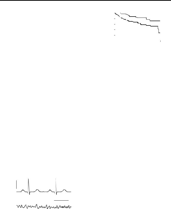
Ventricular fibrillation is a lethal malfunction of the heart. Normally the heart beats about once a second, and is controlled by electrical signals that occur in a predictable, periodic way. The heart’s electrical activity, called the electrocardiogram (ECG), can be measured on the surface of the body. A normal ECG is shown in Fig. 1a. If the heart is in a state of ventricular fibrillation, the electrical control of the heart becomes disorganized and chaotic. Instead of producing a normal ECG, the fibrillating heart produces an ECG that looks more like random noise, as shown in Fig. 1b. Rather than contracting in unison, different regions of the heart contract independently, resulting in a quivering that is not effective in pumping blood.
Once the ventricles of the heart start to fibrillate, death follows in minutes. The American Heart Association estimates that in the United States 335,000 people die each year of sudden cardiac death, with most of the deaths attributed to ventricular fibrillation (1). The most effective way to prevent these deaths is to apply a strong electric shock to the heart within the first few minutes after the onset fibrillation (Fig. 2) (2,3). Devices that deliver such shocks are called defibrillators, and come in two types: external and internal. A physician, a paramedic, or even an untrained bystander can use an external defibrillator to apply a shock to an unconscious victim of ventricular fibrillation. The more sophisticated of these devices are automated so that the user need do little more than follow some simple instructions; such devices are called Automated External Defibrillators (AEDs). Internal defibrillators are similar to cardiac pacemakers, and are implanted
0.5 mV
(a)
0.5 s
(b)
Figure 1. (a) A normal electrocardiogram (ECG). (b) The ECG during fibrillation.
|
100 |
|
|
|
|
|
|
|
|
|
|
|
|
|
|
|
Defibrillation |
|
|
||
|
|
|
|
|
|
|
|
|
|
|
|
|
|
|
|
|
|||||
|
80 |
|
|
|
|
|
|
|
|
|
|
|
|
|
|
|
|
|
|||
|
|
|
|
|
|
|
|
|
|
|
|
|
|
|
|
|
|
|
|
|
|
% |
60 |
|
|
|
|
|
|
|
|
|
|
|
|
|
|
|
|
|
|
|
|
Survival |
40 |
|
|
|
|
|
|
|
|
|
|
|
|
Conventional |
|
|
|||||
|
20 |
|
|
|
|
|
|
|
|
|
|
|
|
|
|
|
therapy |
|
|
||
|
|
|
|
|
|
|
|
|
|
|
|
|
|
|
|
|
|
|
|
|
|
|
0 |
|
|
|
|
|
|
|
|
|
|
|
|
|
|
|
|
|
|
|
|
|
0 |
|
1 |
2 |
3 |
4 |
5 |
||||||||||||||
|
|
|
|
|
|
|
|
|
|
|
|
|
|
Year |
|
|
|
|
|
||
Figure 2. The percent survival for high risk patients when treated with conventional drug therapy or with an implanted defibrillator. [Modified and Reproduced with permission from Moss et al., Improved survival with an implanted defibrillator in patients with coronary disease at high risk for ventricular arrhythmia. N. Engl. J. Med., 335: 1933–1940, 1996. see Ref. 2].
into patients who are at risk for ventricular fibrillation. They monitor the electrical activity of the heart and deliver a shock when necessary. Modern defibrillators can also function as pacemakers, and are called Implantable Cardioverter Defibrillators (ICDs).
EXTERNAL DEFIBRILLATORS
An external defibrillator works by applying a shock through electrodes on the surface of the body. Automated external defibrillators are becoming common in schools, on airplanes, and at other public places. A typical AED is shown in Fig. 3. Each electrode has an area of at least 50 cm2 and is attached to the skin by a self-adhesive pad. A conducting gel should always be placed between the skin and the electrode to reduce the skin resistance. The current passes from the electrodes through the entire torso, with only a fraction of it reaching the heart.
A defibrillator works by charging a capacitor to a high voltage and then discharging it through the patient’s body (Fig. 4). When the switch S is to the left, a capacitance of about 200 mF is charged to 1500 V, implying a stored charge of 0.3 C and a stored energy of 225 J. Move the switch to the right, and the capacitor discharges through the resistance of the patient’s body (50 V or more), generating a peak current of 30 A that decays exponentially with a time constant of 10 ms.
An actual defibrillator circuit is more complicated than shown in Fig. 4. For example, the battery pack used to power an AED typically has a voltage of 12 V. A high voltage power supply is needed to raise this voltage to the level necessary to charge the capacitor. Also, many defibrillators use a biphasic, truncated-exponential waveform, which is more effective for defibrillation than a monophasic wave form (Fig. 5). The biphasic waveform is produced by discharging the capacitor part way, then reversing the polarity of the leads, followed by further discharge. Switching circuitry that functions at high voltages is required.
406
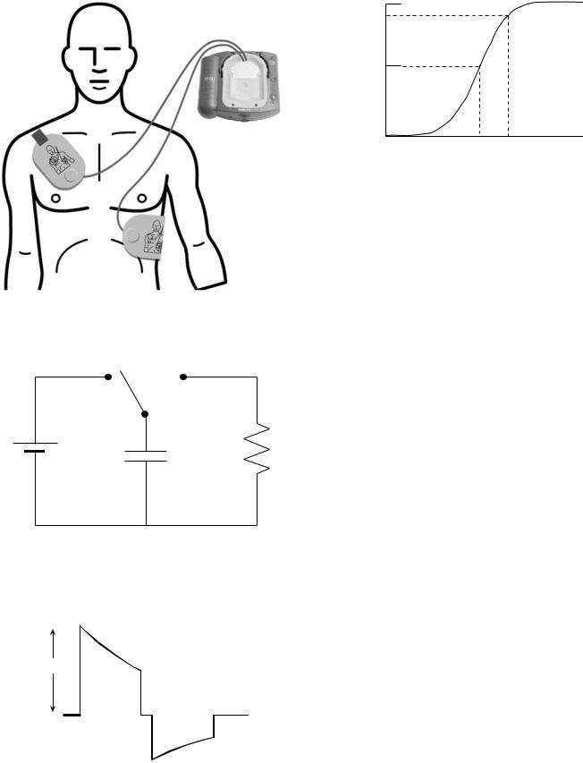
Figure 3. An automated external defibrillator (AED). This figure appears courtesy of Philips Medical Systems.
S
R
V
C
Figure 4. A simplified defibrillator circuit, where V is the voltage of the power supply, C is the capacitor, R is the resistance of the body, and S is a switch.
1500 V
 5 ms
5 ms 
Figure 5. A typical biphasic, truncated exponential waveform used in many defibrillators.
DEFIBRILLATORS 407
100
%
Success
50
0
ED50 ED90
Shock Strength (J)
Figure 6. Defibrillation success follows a sigmoidal probability curve. The shock strength corresponding to a 50% success rate is called ED50 (for effective dose, 50%).
The word ‘‘automatic’’ in the term Automatic External Defibrillator means that the device can decide for itself if defibrillation is necessary. The AED monitors the electrocardiogram, and enough memory is included in the machine to store the ECG data. Also present are electronics that allow the device to analyze the ECG and decide if the ventricles are fibrillating. If they are, the AED will tell the caregiver to shock the patient. Most AEDs provide both written and oral instructions about how to attach the electrodes and operate the device. In theory, minimal training is required.
The success rate of defibrillation follows a probability curve like that shown in Fig. 6: the higher the shock energy, the higher the probability of defibrillation. A shock strength corresponding to a 50% success rate is known as ‘‘ED50’’. To reduce the probability of a failed shock, physicians often use strengths of about ED90. Unwanted side effects also increase with shock energy, so an AED usually shocks with a relatively low energy first, say 200 J. If that fails, it delivers shocks of increasing energy up to a maximum of 360 J.
External defibrillators used in hospitals and ambulances are similar to AEDs, except that they are not automatic (the physician decides when to shock a patient rather than the device) and they can often be powered by plugging into the hospital’s electric power grid instead of, or in addition to, relying on batteries.
IMPLANTABLE DEFIBRILLATORS
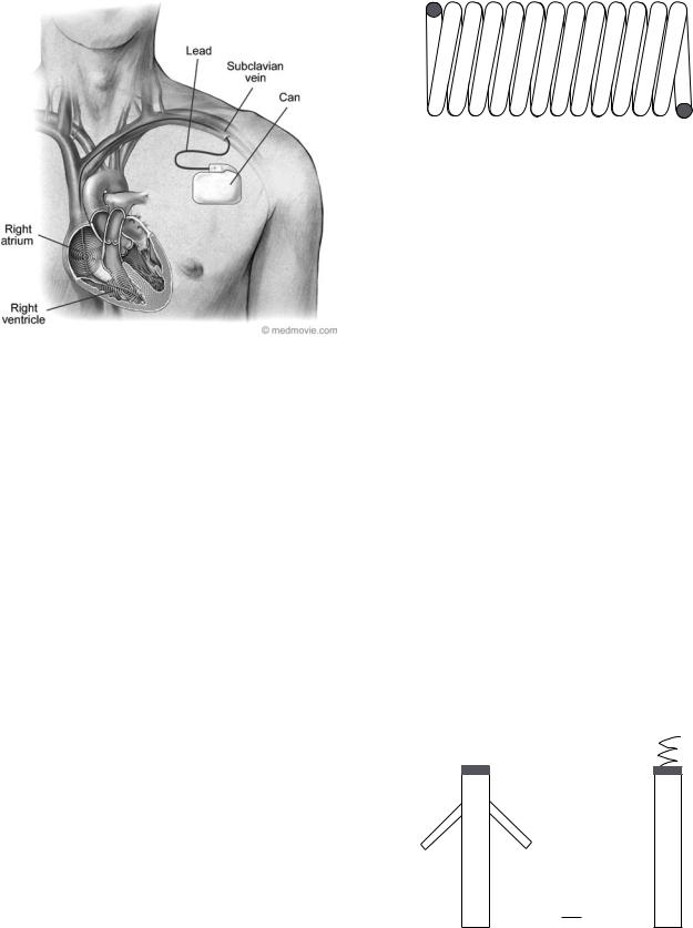
An implantable cardioverter defibrillator resembles a pacemaker, but its circuitry is similar to that in an AED. The battery, capacitor, and electronics are enclosed in a metal case (titanium or stainless steel), which is implanted under the skin in the chest (Fig. 7). The typical size of the case, or ‘‘can ’’, is 50 50 15 mm. The can often serves as one of the ICD electrodes.
The capacitors in an ICD are only slightly smaller ( 125 mF) than in an AED, but in an ICD the capacitor is charged to a voltage of only 600 V, implying a charge of 0.075 C and an energy of 23 J. An ICD delivers about onetenth the energy that an AED does, but in an ICD the shock is delivered through electrodes placed within the heart and is therefore just as effective for defibrillation. Tissue impedance for an ICD is at least 50 V, implying a discharge
408 DEFIBRILLATORS
Figure 7. An implantable cardioverter defibrillator (ICD).
time constant of 5 ms. Many ICDs contain two 250 mF capacitors charged in parallel, to give a total capacitance of 500 mF. When discharged, the connection of the capacitors is changed so they are in series, resulting in the capacitance of 125 mF mentioned earlier. One advantage of this technique is that when in parallel each capacitor needs to be charged to a voltage of only 300 V, which becomes a total voltage of 600 V when placed in series. Most ICDs have a maximum shock energy of 30 J.
Lithium-type batteries, often lithium silver vanadium oxide, power ICDs. Two such batteries in series provide6 V. Since the capacitor voltage is 600 V, the batteries are used to power a high voltage power supply. They are implanted in the patient’s body, so changing them requires surgery, implying that battery lifetime is important. Lifetime is often measured in ampere-hours (A h) (equivalent to a charge of 3600 C), and a typical battery is rated at3 A h. If each time the capacitor is charged uses 0.075 C, the battery should be able to deliver thousands of shocks. However, the battery performance begins to decay before its total charge is exhausted, and also it must provide power for continuous monitoring of the ECG and other functions, so its observed lifetime is 5 years. Another important property of a battery is the time required to charge the capacitor. Typically, the battery takes 10–20 s to generate a full charge. If this time increased significantly, it would delay the delivery of the shock. The voltage decays gradually and predictably throughout the lifetime of a lithium silver vanadium oxide battery, so that the voltage can be used as an indicator of the battery’s remaining useful life.
The electrodes and their leads are critical components of an ICD. Unlike the electrodes in an AED, ICD electrodes are implanted inside a beating heart and must continue to function there for years. Many ICD malfunctions arise because of problems with the leads. Like pacemaker leads, ICD leads are made from coils of wire to make them flexible and avoid breaks (Fig. 8). They are insulated, except at the
Figure 8. The conductor in the lead is often in the form of a coil to increase its flexibility and reduce mechanical stresses in the metal.
electrodes, by silicone rubber or polyurethane. A typical lead contains three electrodes: one for pacing and sensing, and two larger ones for defibrillation. An ICD lead is affixed to cardiac tissue on the inner (endocardial) surface of the heart. Often the tissue is damaged (inflammation, followed by fibrosis) in the area in contact with the lead tip. Steroid eluting leads minimize the tissue damage by slowly releasing the corticosteroid dexamethasone sodium phosphate. The ICD lead must be attached to the endocardial surface to prevent it from becoming dislodged. Some leads use a ‘‘passive’’ fixation technique consisting of plastic tines on the lead tip that become entangled in the trabeculae on the endocardial surface of the right ventricle (Fig. 9a). Other leads use an ‘‘active’’ fixation technique consisting of a metal helix, similar to a corkscrew, that is screwed into the endocardium (Fig. 9b). The defibrillation shock is delivered through a large electrode located many millimeters back from the lead tip. In some cases, current is passed through two electrodes (one in the right ventricle and one in the right atrium, as shown in Fig. 7), and in other cases the shock is delivered between one electrode and the defibrillator can.
The ICD recording lead senses the several-millivolt ECG signal within the heart. Two parameters that the ICD uses to detect abnormal arrhythmias are heart rate and arrhythmia duration. The ICDs use sophisticated algorithms to determine from the ECG if an arrhythmia is present, and these algorithms differ between manufacturers. Sufficient memory is included in the ICD to store ECGs before, during, and after a shock. Figure 1 shows that the ECG from ventricular fibrillation has a smaller amplitude than the normal ECG, making detection of fibrillation challenging. Information about the defibrillator,
|
Tip |
Screw |
|
|
|
(a) |
|
(b) Tip |
Tines |
|
Tines |
1 mm
Figure 9. Distal end of a lead. (a) Passive fixation for attaching the lead to the endocardial surface of the heart using plastic tines. (b) Active fixation using a metal helix that is screwed into the heart wall.
e.g., the status of the battery and the lead impedance, as well as ECG traces, can be obtained through telemetry. Modern ICDs use the medical implant communications system radio frequency band (402–405 MHz). Most ICDs can be reprogrammed using telemetry.
When implanting an ICD, the physician must choose between a single-chamber and a dual-chamber defibrillator. Single-chamber devices have a single lead with the sensing electrode placed in the right ventricle. Their advantage is simplicity, longevity, and fewer complications. Dual-chamber devices have two leads: one sensing the right atrium and one sensing the right ventricle. Patients who rely on the ICD for pacing as well as defibrillation may benefit from the dualchamber design. For example, a patient with a problem in the sinus node, which is located in the right atrium and serves as the heart’s natural pacemaker, may respond best to atrial pacing. The atrial lead would then be for pacing, and the ventricular lead for defibrillation.
A cardiologist usually implants an ICD with the patient under local, not general, anesthesia. Typically, implantation requires an overnight hospital stay, although sometimes it is performed as an outpatient procedure. The ICD can is placed in a ‘‘pocket’’ under the skin in the upper chest, in the pectoral region. The lead is introduced into the subclavian vein, often by puncturing the vein with a needle, and then advanced into the right atrium under fluoroscopic view. A ventricular lead passes through the tricuspid valve between the right atrium and the right ventricle, and then is placed in contact with the endocardium near the apex of the heart (Fig. 7). After the implantation, the cardiologist tests the device by inducing fibrillation and then shocking the heart to check that defibrillation is successful.
The ‘‘C’’ in the term ICD stands for ‘‘cardioversion,’’ which is a type of shock therapy for treating any rapid arrhythmia other than ventricular fibrillation. Typically, a physician uses cardioversion to treat atrial fibrillation or a ventricular tachycardia (a rapid but still organized beating of the ventricles), both serious abnormalities but neither immediately life threatening. The shock strength used during cardioversion may be weaker than or similar to that used for defibrillation, depending on the type of abnormality. Cardioversion often uses information from the ECG to time the shock optimally, whereas defibrillation shocks are delivered without any such timing.
MECHANISMS OF DEFIBRILLATION
Defibrillators have been developed empirically without a complete understanding of the mechanism of defibrillation. Many researchers are studying this important problem (4). The mechanism of defibrillation is closely tied to the mechanism of arrhythmia induction by an electrical shock. In order to initiate an arrhythmia, a shock must be given during the vulnerable period (during the time of repolarization of the ventricular action potential). A very weak shock during the vulnerable period has little effect. A stronger shock can induce an arrhythmia; the lowest strength that induces an arrhythmia is called the ‘‘lower limit of vulnerability’’. An even stronger shock will not cause
DEFIBRILLATORS 409
an arrhythmia; the lowest strength above the lower limit of vulnerability for which an arrhythmia is not induced is called the ‘‘upper limit of vulnerability’’. In order to defibrillate, a shock must be at least as strong as the upper limit of vulnerability. If not, a shock that would otherwise successfully defibrillate the heart could restart a new arrhythmia that might decay quickly into fibrillation.
One of the more difficult issues in defibrillation research is determining exactly where, when, and how a shock affects cardiac tissue (5). The crucial question is how the shock alters the transmembrane potential (the voltage across the cell membrane), because it is the transmembrane potential that opens and closes voltage gated ion channels, thereby causing an action potential and wave front propagation. A simple, one-dimensional (1D) model of current flow through the heart wall suggests that the transmembrane potential caused by a shock is large only within a few length constants ( 1 mm) of the heart’s surface. This model cannot be correct, because fibrillation occurs throughout the heart and the shock must affect a large fraction of the cardiac tissue—not just a thin surface layer—if it is to defibrillate. What then is the mechanism by which a shock alters transmembrane potential deep in the heart wall? This question has not yet been answered definitively, but recent evidence suggests that tissue anisotropy and fiber curvature plays a key role (6).
Scientists continue to study defibrillation even as engineers improve defibrillator designs empirically. How increased fundamental knowledge about defibrillation will improve defibrillators is an open question. Nevertheless, defibrillators contribute crucially to the treatment of cardiac arrhythmias. They represent the best, and often only, option for patients with ventricular fibrillation.
BIBLIOGRAPHY
1.American Heart Association. Heart Disease and Stroke Statistics—2005 Update. Dallas, TX.: American Heart Association; 2004.
2.Moss AL, et al. Improved survival with an implanted defibrillator in patients with coronary disease at high risk for ventricular arrhythmia. Multicenter Automatic Defibrillator Implantation Trial Investigators. N Engl J Med 1996;335 (26):1933–1940.
3.The Antiarrhythmias Versus Implantable Defibrillators (AVID) Investigators, A comparison of antiarrhythmic-drug therapy with implantable defibrillators in patients resuscitated from near-fatal ventricular arrhythmias. N Engl J Med 1997; 337:1576–1583.
4.Ideker RE, Chattipakorn TN, Gray RA. Defibrillation mechanisms: the parable of the blind men and the elephant. J Cardiovasc Electrophysiol 2000;11:1008–1013.
5.Roth BJ, Krrassowska W. The induction of reentry in cardiac tissue. The missing link: How electric fields alter transmembrane potential. Chaos 1998;8:204–220.
6.Trayanova NA. Concepts of ventricular defibrillation. Philos Trans R Soc London A 2001;359:1327–1337.
Further Reading
Jeffrey K. Machines in our Hearts: The Cardiac Pacemaker, The Implantable Defibrillator, and American Health Care. Baltimore: The Johns Hopkins University Press; 2001. An excellent history of the pacemaker/defibrillator industry.