

- •VOLUME 2
- •CONTRIBUTOR LIST
- •PREFACE
- •LIST OF ARTICLES
- •ABBREVIATIONS AND ACRONYMS
- •CONVERSION FACTORS AND UNIT SYMBOLS
- •CARBON.
- •CARDIAC CATHETERIZATION.
- •CARDIAC LIFE SUPPORT.
- •CARDIAC OUTPUT, FICK TECHNIQUE FOR
- •CARDIAC OUTPUT, INDICATOR DILUTION MEASUREMENT OF
- •CARDIAC PACEMAKER.
- •CARDIAC OUTPUT, THERMODILUTION MEASUREMENT OF
- •CARDIOPULMONARY BYPASS.
- •CARDIOPULMONARY RESUSCITATION
- •CARTILAGE AND MENISCUS, PROPERTIES OF
- •CATARACT EXTRACTION.
- •CELL COUNTER, BLOOD
- •CELLULAR IMAGING
- •CEREBROSPINAL FLUID.
- •CHEMICAL ANALYZERS.
- •CHEMICAL SHIFT IMAGING.
- •CHROMATOGRAPHY
- •CO2 ELECTRODES
- •COBALT-60 UNITS FOR RADIOTHERAPY
- •COCHLEAR PROSTHESES
- •CODES AND REGULATIONS: MEDICAL DEVICES
- •CODES AND REGULATIONS: RADIATION
- •COGNITIVE REHABILITATION.
- •COLORIMETRY
- •COMPUTERS IN CARDIOGRAPHY.
- •COLPOSCOPY
- •COMMUNICATION AIDS FOR THE BLIND.
- •COMMUNICATION DEVICES
- •COMMUNICATION DISORDERS, COMPUTER APPLICATIONS FOR
- •COMPOSITES, RESIN-BASED.
- •COMPUTED RADIOGRAPHY.
- •COMPUTED TOMOGRAPHY
- •COMPUTED TOMOGRAPHY SCREENING
- •COMPUTED TOMOGRAPHY SIMULATOR
- •COMPUTED TOMOGRAPHY, SINGLE PHOTON EMISSION
- •COMPUTER-ASSISTED DETECTION AND DIAGNOSIS
- •COMPUTERS IN CARDIOGRAPHY.
- •COMPUTERS IN THE BIOMEDICAL LABORATORY
- •COMPUTERS IN MEDICAL EDUCATION.
- •COMPUTERS IN MEDICAL RECORDS.
- •COMPUTERS IN NUCLEAR MEDICINE.
- •CONFOCAL MICROSCOPY.
- •CONFORMAL RADIOTHERAPY.
- •CONTACT LENSES
- •CONTINUOUS POSITIVE AIRWAY PRESSURE
- •CONTRACEPTIVE DEVICES
- •CORONARY ANGIOPLASTY AND GUIDEWIRE DIAGNOSTICS
- •CRYOSURGERY
- •CRYOTHERAPY.
- •CT SCAN.
- •CUTANEOUS BLOOD FLOW, DOPPLER MEASUREMENT OF
- •CYSTIC FIBROSIS SWEAT TEST
- •CYTOLOGY, AUTOMATED
- •DECAY, RADIOACTIVE.
- •DECOMPRESSION SICKNESS, TREATMENT.
- •DEFIBRILLATORS
- •DENTISTRY, BIOMATERIALS FOR.
- •DIATHERMY, SURGICAL.
- •DIFFERENTIAL COUNTS, AUTOMATED
- •DIFFERENTIAL TRANSFORMERS.
- •DIGITAL ANGIOGRAPHY
- •DIVING PHYSIOLOGY.
- •DNA SEQUENCING
- •DOPPLER ECHOCARDIOGRAPHY.
- •DOPPLER ULTRASOUND.
- •DOPPLER VELOCIMETRY.
- •DOSIMETRY, RADIOPHARMACEUTICAL.
- •DRUG DELIVERY SYSTEMS
- •DRUG INFUSION SYSTEMS
266 COMPUTED TOMOGRAPHY SIMULATOR
54.Miettinen OS, Henschke CI. CT screening for lung cancer: coping with nihilistic recommendations. Radiology 2001;221: 592–596.
55.Patz EF, Jr. Black WC, Goodman PC. CT screening for lung cancer: not ready for routine practice. Radiology 2001;221: 587–591.
56.Swensen SJ, et al. Screening for lung cancer with low-dose spiral computed tomography. Am J Respir Crit Care Med 2002;165:508–513.
57.Sone S, et al. Results of three-year mass screening programme for lung cancer using mobile low-dose spiral computed tomography scanner. Br J Cancer 2001;84:25–32.
58.Nawa T, et al. Lung cancer screening using low-dose spiral CT: results of baseline and 1-year follow-up studies. Chest 2002; 122:15–20.
59.Garg K, et al. Randomized controlled trial with low-dose spiral CT for lung cancer screening: Feasibility study and preliminary results. Radiology 2002;225:506–510.
60.Sobue T, et al. Screening for lung cancer with low-dose helical computed tomography: anti-lung cancer association project. J Clin Oncol 2002;20:911–920.
61.Mahadevia PJ, et al. Lung cancer screening with helical computed tomography in older adult smokers: a decision and cost-effectiveness analysis. JAMA 2003;289:313–322.
62.Thompson DE, et al. Cancer incidence in atomic bomb survivors. Part II: Solid tumors, 1958–1987. Radiat Res 1994;137: S17–67.
63.NRC. Health effects of exposure to low levels of ionizing radiation: BEIR V. Washington (DC): National Academy Press; 1990.
64.Gilbert ES, et al. Lung cancer after treatment for Hodgkin’s disease: focus on radiation effects. Radiat Res 2003;159: 161–173.
65.Tokarskaya ZB, et al. Interaction of radiation and smoking in lung cancer induction among workers at the Mayak nuclear enterprise. Health Phys 2002;83:833–846.
66.Melloni B, Vergnenegre A, Lagrange P, Bonnaud F. Radon and domestic exposure. Rev Mal Respir 2000;17:1061–1071.
67.Morrison HI, Villeneuve PJ, Lubin JH, Schaubel DE. Radonprogeny exposure and lung cancer risk in a cohort of Newfoundland fluorspar miners. Radiat Res 1998;150:58–65.
68.Neugut AI, et al. Increased risk of lung cancer after breast cancer radiation therapy in cigarette smokers. Cancer 1994; 73:1615–1620.
69.Pershagen G, et al. Residential radon exposure and lung cancer in Sweden. N Engl J Med 1994;330:159–164.
70.Samet JM, et al. Lung cancer mortality and exposure to radon progeny in a cohort of New Mexico underground uranium miners. Health Phys 1991;61:745–752.
71.Hornung RW, Deddens J, Roscoe R. Modifiers of exposureresponse estimates for lung cancer among miners exposed to radon progeny. Environ Health Perspect 1995;103(Suppl 2): 49–53.
72.Pierce DA, Sharp GB, Mabuchi K. Joint effects of radiation and smoking on lung cancer risk among atomic bomb survivors. Radiat Res 2003;159:511–520.
73.Brenner DJ. Radiation risks potentially associated with lowdose CT screening of adult smokers for lung cancer. Radiology 2004;231:440–445.
74.FDA. Full-body CT scans: What you need to know. DHHS Publication FDA (03)-0001. Available at www.fda.gov/cdrh/ct/ ctscansbro.html, U.S. Food and Drug Administration, Rockville (MD); 2003.
75.Brant-Zawadzki M. CT screening: why I do it. AJR Am J Roentgenol 2002;179:319–326.
76.Illes J, et al. Self-referred whole-body CT imaging: current implications for health care consumers. Radiology 2003;228: 346–351.
77.Holtz A. Whole-body CT screening: Scanning or scamming? Oncol Times 2003;25:5–7.
78.Berland LL, Berland NW. Whole-body computed tomography screening. Semin Roentgenol 2003;38:65–76.
79.Beinfeld MT, Wittenberg E, Gazelle GS. Cost-effectiveness of whole-body CT screening. Radiology 2005;234:415–422.
80.Casola G, et al. Whole body CT screening: Spectrum of findings and recommendations. Radiology 2002;225(Suppl.):317.
81.Casarella WJ. A patient’s viewpoint on a current controversy. Radiology 2002;224:927.
82.Brenner DJ, Elliston CD. Estimated radiation risks potentially associated with full-body CT screening. Radiology 2004 232:735–738.
83.ICRP. 1990 Recommendations of the International Commission on Radiological Protection: Publication 60. Oxford: Pergamon; 1991.
84.Fishman EK, Horton KM. What application should you offer in a whole body CT screening center? Available at www.screeningctisus.com/articles/screeningctisus.html.
85.Hoyert DL, et al. Deaths: final data for 1999. Natl Vital Stat Rep 2001;49:1–113.
86.Evens RG, Mettler FA. National CT use and radiation exposure: United States 1983. AJR Am J Roentgenol 1985;144: 1077–1081.
87.Bahador B. Trends in diagnostic imaging to 2000. London: Financial Times Pharmaceuticals and Healthcare Publishing; 1996.
88.UNSCEAR. Sources and effects of ionizing radiation: United Nations Scientific Committee on the Effects of Atomic Radiation: UNSCEAR 2000 report to the General Assembly. United Nations, New York; 2000.
89.Linton OW, Mettler FA, Jr. National conference on dose reduction in CT, with an emphasis on pediatric patients. AJR Am J Roentgenol 2003;181:321–329.
See also BONE DENSITY MEASUREMENT; COMPUTER-ASSISTED DETECTION AND DIAGNOSIS.
COMPUTED TOMOGRAPHY SIMULATOR
XIANGYANG TANG
GE Healthcare Technologies
Waukesha, Wisconsin
GE WANG
University of Iowa
Iowa City, Iowa
INTRODUCTION
The development of conformal radiation therapy (RT) and computerized treatment planning dates back to the late 1950s (1,2). The first milestone of computerized treatment planning is the invention of beam’s eye view (BEV) display in the late 1970s (3,4). Up to now, along with surgery and chemotherapy, conformal RT has become the most effective measure for curative or palliative management of cancers at various anatomic sites (5). The biological mechanism underlying RT is that radiation damages crucial structures, such as deoxyribonucleic acid (DNA), of a cell, resulting in cell death, whether the cell is cancerous or normal, when the biologically damaged cell cannot be repaired by itself (5). The radiation dose delivered by RT is toxic to
normal biological tissues and organs while it kills abnormal cells to cure cancer or palliate the local symptom of a malignant tumor (5). If the radiation dose distribution is made sufficiently concentrated on a targeted cancerous volume and tolerable over nearby normal anatomic structures, the cells within the cancerous volume may be killed while those within the normal organs or tissues survive. Hence, the ultimate goal of radiation therapy is to cure or control the cancer by precisely delivering an adequate and a homogeneous radiation dose to the targeted cancerous volume while maintaining the unavoidable dose to surrounding biological structures, particularly those critical organs or tissues that are very sensitive to radiation dose, such as eye, testis, lung, spinal cord, brain, and so on, below the biological toxicity tolerance. To improve the therapeutic ratio while decreasing the occurrence of acute or chronic side effects caused by radiation toxicity as much as possible, an administration of fractionated radiation therapy process has been clinically proven to be more efficient than a ‘‘lump sum’’ radiation delivery (5).
A typical conformal RT process consists of diagnostic data acquisition, simulation, treatment planning, treatment verification, and treatment delivery, although its implementation can be customized based upon available personnel and resources. Intuitively, a malignant tumor cannot be cured or its local symptom cannot be controlled if it misses the adequate radiation dose prescribed by a radiation oncologist. Meanwhile, the normal cells of surrounding tissues or organs can be fatally damaged if it absorbs the radiation dose supposed to be delivered to a targeted cancerous tumor. Consequently, among all factors compromising the success of a radiation therapy process, the geometrical imprecision or inaccuracy caused by patient localization and immobilization, as well as inadequate dose during treatment delivery, play dominant roles. Moreover, since a radiation therapy process is usually administrated in a fractionated manner, the patient position reproducibility between treatment delivery fractions is also of crucial importance. The maintenance of geometrical precision, accuracy, and reproducibility, which can never be overemphasized, are the tasks of simulation, while the warranty of delivering an adequate radiation dose at a homogenous distribution are the tasks of radiation treatment planning.
Conventionally, being carried out by a physician on a simulator in which two-dimensional (2D) imaging techniques are usually utilized, the simulation in conformal RT is an interactive and iterative process. Instead of using photons at the MeV energy level that are utilized in radiation treatment delivery, photons at the keV energy level, that is, X-ray, are utilized in the simulation to provide fluoroscopy for beam designing, in which an image intensifier or flat panel imager is usually employed. Moreover, X-ray source and film-based radiography are usually utilized for portal verification. In the beginning of the simulation, a radiation oncologist identifies the clinical target volume (CTV) by initially specifying the gross target volume (GTV) with a clinical margin added by taking the possible surrounding metastases and spreads into account (5). A planning target volume (PTV) is eventually defined by taking an extra margin into account to compensate for systematic geometrical mismatch between the simulator and the
COMPUTED TOMOGRAPHY SIMULATOR |
267 |
treatment machine, as well as geometrical error caused by the beam setup uncertainty and internal organ motion
(6). It is important to state that, such an extra margin is crucial to the success of a radiation therapy, because the internal organ of a patient is always moving, no matter how perfect the patient localization, immobilization, and the geometric match between simulator and treatment machines can be achieved. By mimicking the geometry of a radiation therapy machine, such as a linear accelerator (LINAC), and with the availability of those 2D imaging techniques mentioned above, the conventional simulation generates a delineation of PTV and layout of radiation fields, including the number and orientation of beams, aperture of collimator, shape and size of field, as well as the specification of beam blocker, wedge, or compensator and markers. Since the geometry of a conventional simulator is exactly the same as that of a treatment machine, a spatial and geometrical integrity between them can be achieved if radioopaque markers are placed on a patient’s skin or at appropriate anatomic landmarks, for example, the sternum for a patient with breast cancer. The conventional simulation in conformal radiation therapy is an online iterative process. Such an on-line process is inefficient in terms of patient throughput, since it requires a patient to remain in the simulator couch during the entire simulation process. It is very tough, if not impossible, to obtain an optimized conventional simulation in conformal radiation therapy, because this tedious and time-consuming simulation process is greatly dependent on the skill or experience of the physician committed to the task.
Intrinsically, the anatomic structure of a human being is three-dimensional (3D), and can be mapped to 3D models representing its geometric, pathologic, and physiologic characteristics, respectively. The advent of clinical X-ray computed tomography (CT) in the early 1970s was a revolution over 2D imaging technology, making the 3D modeling of a patient a reality. However, the X-ray CT scanner in its early stage was not capable of providing high quality, especially high spatial resolution, tomographic images of a patient volume within an acceptable or tolerable time. Nevertheless, the potentiality offered by X-ray CT technology for RT was well recognized then. In the 1980s, CT technology evolved dramatically while great progress simultaneously had been accomplished in 3D computer visualization technologies. By combining the state-of-the-art CT technology with modern 3D computer visualization, the concept of CT simulator or virtual simulator was formed in the late 1980s (7–9). Since then, enormous effort and resources were invested in the research and development (R&D) of CT or virtual simulator, resulting in numerous CT or virtual simulators commercially available in the market. For convenience, a CT simulator hereafter refers to either a CT simulator or a virtual simulator unless otherwise specified.
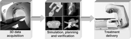
As shown in Fig. 1, a CT simulator consists of a radiation therapy dedicated CT scanner (viz., RT-dedicated CT scanner) and a software workstation. The RT-dedicated CT scanner is to provide a 3D model of the patient to be treated by acquiring contiguous tomographic images over a volume of interest. The software workstation is to carry out simulation based on the 3D anatomic structures and clinical
268 COMPUTED TOMOGRAPHY SIMULATOR
Figure 1. A schematic diagram showing the process of 3D conformal RT using a CT simulator: (a) Three-dimensional patient data acquisition through a RT dedicated CT scanner; (b) CT simulation, treatment planning and verification; (c) Treatment delivery via a LINAC.
information revealed by the 3D model of the patient. In general, the simulation software of a CT simulator can be either stand-alone or an embedded part of a treatment planning system. By integrating an RT-dedicated CT scanner and simulation software, a CT-simulator generally conducts the following tasks: patient positioning, patient immobilization, 3D patient data set acquisition by CT scanning, identification of a target volume (GTV, CTV, and PTV) and surrounding vital normal tissues and organs, placement of beams (number, orientation, isocenter, and collimator aperture), field design (beam shaper, blocker, wedge and compensator), as well as generation of portal images, such as digitally reconstructed radiography (DDR) and other instructions exported to a treatment planning and RT machine (10–17). In the following sections, these tasks are described in detail.
THREE-DIMENSIONAL COMPUTED TOMOGRAPHY PATIENT DATA ACQUISITION
A CT scanner is the cornerstone of a CT simulator for treatment planning and delivery using 3D conformal RT. With a focus on diagnostic imaging, CT technology has been substantially improved over the past three decades and became the most popular tomographic imaging modality in clinics (18,19). With the impressive progresses in CT technology, particularly the image reconstruction methods for multidetector row CT and volumetric CT (20–22), a state-of-the-art diagnostic CT scanner has well satisfied the requirement posed by RT. Unfortunately, however, a start-of-the-art diagnostic CT scanner usually cannot be readily used in a CT simulator for RT treatment planning, because the gantry aperture diameter of a diagnostic CT scanner is usually 70.0 cm, which cannot guarantee a smooth accommodation of a patient and necessary immobilization devices, for example, the arm holder utilized in breast cancer radiation therapy (14). As a result, RT-dedicated CT scanners have been developed by major medical CT scanner manufacturers and are currently available on the market. The gantry aperture diameter of an RT-dedicated CT scanner ranges from 80 to 85 cm with a display field of view (DFOV) between 60 and 65 cm, which can handle virtually all clinical situations. Technical parameters of a typical RT-dedicated CT scanner are listed in Table 1. The performance of an RT-dedicated CT scanner should be periodically calibrated and verified (14,17). It is interesting to note that, although its overall performance is inferior to that of a state-of-the-art diagnostic CT scanner, a currently available RT-dedicated CT scanner can serve
radiation therapy very well (12). One of the major reasons for such a technical delay is a relatively small market volume of RT-dedicated CT scanners in comparison to that of diagnostics CT scanners. Considering the fast evolution of the diagnostic CT scanner and the technical catching up of the RT-dedicated CT scanner in X-ray detector z coverage and scanning speed, it is very hopeful for a future RT-dedicated CT scanner to have the overall performance of a current diagnostic CT scanner.
In general, the protocols used for diagnostic CT imaging can be used correspondingly by an RT-dedicated CT scanner to acquire a 3D patient data set for CT simulation, although a trade-off between the spatial resolution along the longitudinal direction of a patient (image slice thickness) and the total number of tomographic images has to be made in practice. As shown in Table 1, whereas the thinnest available slice thickness in a commercial RTdedicated CT scanner is between 1.0 and 2.0 mm, an image slice thickness thinner than 3.0 mm is usually acceptable to render DRR for portal verification (23).
PATIENT POSITIONING AND IMMOBILIZATION
It has to be emphasized that, to guarantee a geometrical match between the CT scanning and the treatment delivery, the patient has to be in exactly the same position with all the immobilization devices, such as foam body casts, thermoplastic head masks (24), and stereotactic frames (25), in place. In addition to an enlarged gantry aperture to accommodate a patient and immobilization devices, an RT-dedicated CT scanner has a flat top patient couch that is exactly the same as the one used in a treatment machine so that an exact geometrical match and reliable patient position reproducibility can be achieved between the RT-dedicated CT scanner and the treatment system. As illustrated below, all the tasks accomplished by a CT simulator are solely dependent on the spatial integrity of the 3D patient data set acquired by an RT-dedicated CT scanner.Also,theimportanceofgeometricaccuracyandmatch between the CT scanner and RT machine, as well as the reproducibility of patient position, can never be overstated.
In principle, the orthogonal laser beams existing in an RT-dedicated CT scanner gantry can be employed to mark the isocenter of a target volume. However, to assure a convenient and efficient marking process on the patient’s skin or other anatomic landmarks, it is preferable to have external laser devices installed on the side wall and ceiling of the room where the RT-dedicated CT scanner is installed (14). The laser beams on the side wall (transaxail and
|
COMPUTED TOMOGRAPHY SIMULATOR |
269 |
|
Table 1. Primary Technical Parameters of a Typical Radiation Therapy Dedicated CT Scanner |
|
|
|
|
|
|
|
Scan mode |
Axial; Helical |
|
|
|
|
|
|
Scan speed (s/3608 gantry rotation) |
1.0, 2.0, 3.0, 4.0 |
|
|
Number of detector row |
4 |
|
|
Diameter of gantry bore (mm) |
800.00 |
|
|
Display FOV (mm) |
650.0 |
|
|
X-ray tube |
Current: 10–440 mA, 5mA increments |
|
|
|
kVp: 80, 100, 120, 140 |
|
|
|
Power: 0.8–53.2 (kW) |
|
|
|
Heat capacity: 6.3 MU |
|
|
Gantry tilt |
308 |
|
|
Image slice thickness (mm) |
0.625, 1.25, 2.5, 3.75, 5.0, 7.5, 10.0 |
|
|
Dose (mGy/100 mAs) |
CTDI: |
|
|
|
|
Head: 16.5 (center); 17.2 |
|
|
(surface) |
|
|
|
|
Body: 5.6 (center); 11.0 |
|
|
(surface) |
|
|
|
CTDI100: |
|
|
|
|
Head: 17.0 (center); 18.4 |
|
|
(surface) |
|
|
|
|
Body: 5.4 (center); 11.8 |
|
|
(surface) |
|
|
|
CTDIvol: |
|
|
|
|
Head: 17.9 |
|
|
|
Body: 9.7 |
|
In-plane spatial resolution (lp/cm) |
Standard |
Hi-resolution |
|
|
4.2 at 50% MTF |
10.5 at 50% MTF |
|
|
6.8 at 10% MTF |
13.9 at 10% MTF |
|
|
8.5 at 0% MTF |
15.4 at 0% MTF |
|
Low contrast resolution [on 8 in. CATPHAN phantom] |
5mm at 0.3% at 13.3 mGy |
|
|
|
3mm at 0.3% at 37.6 mGy |
|
|
Noise(on AAPM water phantom) |
0.32% þ/ 0.03% at 25.2 mGy (2.52 rad) |
|
|
Image generation speed (s/frame) |
0.17 |
|
|
Image matrix |
512 512 |
|
|
CT number scale |
31743–31743 HU |
|
|
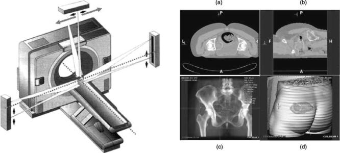
coronal) are fixed to identify the isocenter by moving the patient couch longitudinally and vertically. The laser beam on the ceiling (sagittal) has to be moveable laterally to reach the isocenter of a target volume since the patient couch of a CT scanner is generally not movable laterally. A schematic diagram showing the deployment of external laser beams on an RT-dedicated CT scanner is illustrated in Fig. 2.
There exist two ways to identify the isocenter of a target volume (14). The first way is to place marks on a patient’s skin to obtain the absolute location of the isocenter in the coordinate system of the RT-dedicated CT scanner. Since the coordinate system of the RT-dedicated CT scanner is aligned with that of a treatment machine by geometrical calibration and verification, the isocenter coordinates obtained in such a way are ready for utilization by the treatment machine as long as the patient is appropriately marked. The primary advantage of this manner is the avoidance of any errors due to intermediate geometrical transforms. However, this method requires the involvement of radiation oncologists and physicists simultaneously on site while the patient remains in the couch of
the RT-dedicated CT scanner. Such a process is called a synchronized mode because the identification of a target volume has to be accomplished in real-time as described above. The second way is relatively flexible and can be carried out off-line. The patient with a few radioopaque marks placed on the skin or preferably solid anatomic landmarks goes through a regular CT scanning, and then can immediately leave the hospital. The radioopaque landmarks can be easily placed with the availability of external laser beams of an RT-dedicated CT scanner as introduced above. In the simulation, the isocenter of a target volume can be readily determined by a physicist under the guidance of a radiation oncologist. This way is in an asynchronous mode and provides substantial flexibility for physicians to improve patient throughput and patient comfort.
COMPUTED TOMOGRAPHY SIMULATION
With an RT-dedicated CT scanner, a set of transaxial images covering a volume of interest are obtained and
270 COMPUTED TOMOGRAPHY SIMULATOR
Figure 2. A schematic diagram showing an RT-dedicated CT scanner and its associated external laser beams for patient positioning in 3D conformal RT using a CT simulator for treatment planning (Courtesy Robert L. Steinnhauser, Gammex rmi.)
stored in the simulation workstation. Generally speaking, the 3D data set contains much more information about the patient than can be viewed in the transaxial plane only. For example, with the availability of multiplanar reformatting in other baseline planes (coronal, sagittal, and even oblique), physicians can attain more freedom in visualizing a targeted tumor volume and its geometrical relationship with adjacent normal anatomic structures. The 3D patient data set can be conceived as a virtual patient or a 3D model of the patient to be treated, and a 3D model fiducially represents both anatomic and physical properties of the patient. With modern 3D image processing and visualization techniques that will be described below, the anatomic and physical information of the patient, can be exploited in much more details (13).
Structure Identification
The purpose of a CT simulator is not only to identify the extent of a tumor, but also to provide an unambiguous delineation of the relationship between the targeted tumor volume and its neighboring normal tissues or organs. The basic, but most effective, tool in a CT simulator to identify a tumor is the use of contouring to define the GTV, CTV, and PTV of a targeted tumor volume, in contiguous transaxial tomographic images. The GTV of a cancerous tumor is initially specified by a radiation oncologist via outlining the boundaries of the GTV manually or semiautomatically. As mentioned above, during the target volume defining process, it is necessary to expand the GTV into a CTV by including clinical margins surrounding the GTV. The aim of adding clinical margins is to assure that possible spreading or metastases be included in the targeted volume. Furthermore, recognizing the imperfect geometrical reproducibility over treatment fractions, such as systematic
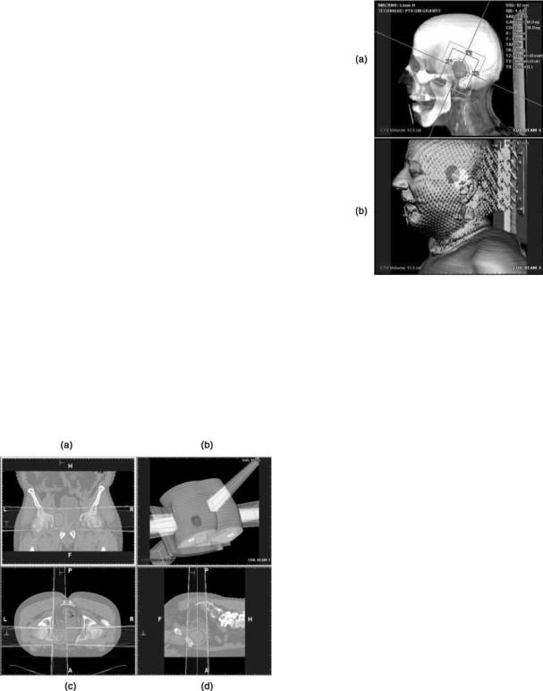
Figure 3. A target volume and its nearby normal critical organ are identified using slice-wise contouring in transaxial image plane (a), sagittal image plane (b), beam’s eye view (c) and operator’s eye view via segmented semitransparent surface rendering (d). In baseline image planes, the CTV is outlined by red, PTV by yellow and the nearby critical organ at risk by green contours, respectively, while colors fill each volume correspondingly in beam’s eye view and operator’s eye view. [Courtesy Dr. Georgios Sakas and Dr. Evelyn A. Firle, Fraunhofer Institute for ComputerGraphics (IGD).] Please see online for color figure.
geometric errors caused by beam setup uncertainty and geometrical mismatch between an RT-dedicated CT scanner and a treatment machine, the random and/or periodic geometrical errors caused by patient and organ motions, such as breathing and swallowing, it is crucial to include an adequate margin into the planed target volume (5,6).
A manual contouring process is conducted by defining the boundary of the GTV, CTV, and PTV, respectively, in every image slice. The image slice can be in any baseline plane, though the transaxial slice is preferably utilized in practice. An example of such a process is illustrated in Fig. 3. The manual contouring operation can also be done in several other slices sequentially, and the boundaries in interim images can be automatically obtained by linear or nonlinear interpolation techniques, as long as the gap between adjacent contoured image slices are within certain threshold. An even more efficient way to carry out the manual contouring operation is to define the boundaries of the target volume on the central transaxial, coronal, and sagittal planes, respectively, and then the target volume can be obtained by automatic 3D linear or nonlinear interpolation techniques available in a CT simulator. On the other hand, a semiautomatic contouring can be accomplished by just placing a seed within the targeted volume, and the boundaries are then determined by thresholding over CT numbers in Housfield units or other characteristics of the voxels in an image. Subsequently, the targeted volume can be obtained through automatic image processing techniques, such as volume growing over contiguous image slices.
Beam Design
Once the targeted cancerous tumor is defined by the techniques presented above, the next step in the simulation is beam design: to determine the number and orientation of beams, aperture of collimators, as well as shape and size of the beam field. Prior to the beam design, a physician has to specify a coordinate system convention based on which simulation is to be conducted, the treatment machine type, and its associated characteristics, such as modality (photon or electron) and energy level of the beam intended for radiation treatment. Usually, a CT simulation workstation provides versatile and powerful 2 and 3D visualization tools and utilities for beam manipulation, and a typical beam designing process in central baseline planes is illustrated in Fig. 4. In the process, the orientation or deployment of beams is specified by machine angle, collimator angle, and patient couch angle, with the beam manipulation tools, such as creating, adding, deleting, mirroring, duplicating, or renaming, in the CT simulator. The isocenter of an identified target volume can be adjusted, and the resultant coordinate system shifts are recorded and exported to a treatment machine. With versatile 2 and 3D visualization tools and utilities, the collimator aperture can be adjusted interactively by clicking and dragging the X- and Y-jaw of a collimator on the display screen of the simulation workstation. The beam field can conform the boundaries of the identified target volume by manipulating various beam shapers (either aperture or shield). A shaper can be either available in the standard set offered by a CT simulator or defined by a physician according to the structure to be conformed. The definition of a new shaper
Figure 4. Beams are designed to deliver radiation treatment to the targetvolumeidentified throughtheprocessshown inFig.3,with the beam manipulating functions provided by a CT simulator in coronal plane (a), operator’s eye view via 3D segmented semitransparent surface rendering (b),transaxial plane (c), and sagittal plane (d). [Courtesy Dr. Georgios Sakas and Dr. Evelyn A. Firle, Fraunhofer Institute for Computer Graphics (IGD).] Please see online for color figure.
COMPUTED TOMOGRAPHY SIMULATOR |
271 |
Figure 5. Modern 3D visualization techniques are extensively utilized in CT simulator to design beams via beam shaper for 3D conformal RT: (a) Beam’s eye view, in which the CTV is filled in red, the PTV is outlined by green contour, the collimator aperture is defined by red rectangle, and the organ at risk (eye) is filled with green; (b) Operator’s eye view using segmented semitransparent surface rendering, in which the PTV is in red, the beam field on the surface in yellow, and the organ at risk in green. [Courtesy Dr. Georgios Sakas and Dr. Evelyn A. Firle, Fraunhofer Institute for Computer Graphics (IGD).] Please see online for color figure.
can be either manual by clicking and dragging on the display screen or automatic by conforming the shaper to the boundaries of the targeted volume. Markers defining the corner of the field can be placed on a patient’s skin or anatomic landmarks via clicking and dragging or typing into corresponding entries on the display screen. Furthermore, a typical CT simulator usually provides numerous utility functions for geometry measurement, such as distance, angle, area and volume, and the measurement results are displayed on the screen while textual annotations can be manipulated simultaneously.
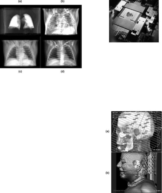
Alternatively, the procedures introduced above can be carried out in the so-called BEV: the most fundamental and powerful 3D visualization technique employed in the simulation. Being illustrated in Fig. 5, the BEV is obtained via DRR by mimicking an X-ray source emanating from exactly the same location corresponding to the radiation focal spot of a treatment machine. With the availability of BEV, the following operations can be readily carried out: adjustment of the beam’s isocenter, adding makers to the corners of a beam field, and manipulating the leaves of a multileaf collimator (MLC). Note that a number of modern image processing techniques can be combined with 3D visualization to highlight interested anatomic features while the interference from noninterested anatomic structures is being removed from visualization. For example, as shown in Fig. 6, by thresholding voxel gray values in an appropriate range, DRRs of the lungs, fat, muscle, other
272 COMPUTED TOMOGRAPHY SIMULATOR
Figure 6. Other examples of modern 3D visualization techniques provided by a typical CT simulator for treatment planning in 3D conformal RT, in which only the interested organs or tissues are displayed: DRR of lung (a); DRR of fat (b); DRR of muscle (c); DRR of all anatomic structure and tissues (d). [Courtesy Dr. Georgios Sakas and Dr. Evelyn A. Firle, Fraunhofer Institute for Computer Graphics (IGD).]
tissues and organs can be exclusively displayed to facilitate target volume identification and contouring, beam deployment, and field designing. Another example of 3D visualization techniques for CT simulation is depth controlling, in which only a slab containing the target volumes and their surrounding structures are displayed. All these DRR-based 3D visualization techniques can be combined wherever they can make a simulation process more productive and reliable. Moreover, other modern 3D visualization techniques, such as surface rendering to generate operator’s eye view or room’s eye view, enable an even smoother and more efficient beam designing process. It is interesting to mention that the transparency in surface rendering can be adjusted to facilitate the simulation (e.g., Figs. 3 and 4).
In practice, various beam blockers to shape the beam field can be made of lead, depleted uranium, or low melting point lead alloy (5,26). Usually, these shapers are customized for individual patients. Such a customization process is time consuming, inefficient, and expensive. Instead of customizing beam shapers for each target volume of each patient, a beam field can be shaped by a multileaf collimator in which two banks of leaves are installed oppositely with each leaf being driven by a computer-controlled step motor (27–29) (see Fig. 7). Through a coordinated movement of these leaves, the beam field can conform various target volumes, provided that the thickness of a leaf is sufficiently small, such as 0.5 or 1.0 cm. Thus, the multileaf collimator is a much more general and efficient beam shaping technique, since it can be repeatedly and unlimitedly utilized in 3D conformal radiation therapy for any targeted volume at any location within a patient. Consequently, the facility for beam shaper fabrication, such as block cutting and compensator making, are no longer
Figure 7. A multileaf collimator used for beam shaping in 3D conformal radiation therapy consists of two banks of metal leaves that are installed oppositely, and each leaf is driven by a computercontrolled step motor or pneumatic device individually.
needed. To suppress the interleaf radiation leakage as much as possible, there usually exists interlocking between adjacent and opposite leaves of a multileaf collimator, which is implemented in a tongue–groove structure. All the beam design techniques introduced above can be readily employed with a multileaf collimator. An example is shown in Fig. 8, in which the deployment of all leaf is illustrated.
It is not an exaggeration to state that, without the aforementioned 3D visualization-based functionalities,
Figure 8. Modern 3D visualization techniques are extensively utilized in CT simulator to design beams via multileaf collimator for 3D conformal radiation therapy: (a) Beam’s eye view, in which the CTV is filled in red, the PTV is outlined by green contour, the collimator aperture is defined by red rectangle, and the organ at risk (eye) is filled with green; (b) Operator’s eye view using segmented semitransparent surface rendering, in which the PTV is in red, the beam field on the surface in yellow, and the organ at risk in green. [Courtesy Dr. Georgios Sakas and Dr. Evelyn A. Firle, Fraunhofer Institute for Computer Graphics (IGD).] Please see online for color figure.
the beam design using a multileaf collimator would be very difficult, if not impossible. Moreover, the optimization of the beam design, in which many plans have to be investigated and compared, via either beam shapers or a multileaf collimator can only be possible with the aid of these functionalities that are provided by a CT simulator.
Protocol Export
Once targeted volumes are identified, beams and their fields are designed, the last step is to export the simulation results to a treatment machine. The simulation results consist of both textual and pictorial information. The textual information usually includes a list of identified structures and their types (targeted cancerous volume, surrounding critical normal organ or tissue, and, etc.), a list of beam setting up parameters corresponding to each targeted volume (machine angles, patient couch angles, isocenter coordinates, field markers, and etc.), and a list of sequential actions to be executed in the treatment delivery process. The pictorial information refers to the pictures and images, such as DRRs, that can be used in the treatment process for planning verification by comparing them with the portal images acquired on the treatment machine.
COMPUTED TOMOGRAPHY SIMULATION
FOR ADVANCED RADIATION THERAPY
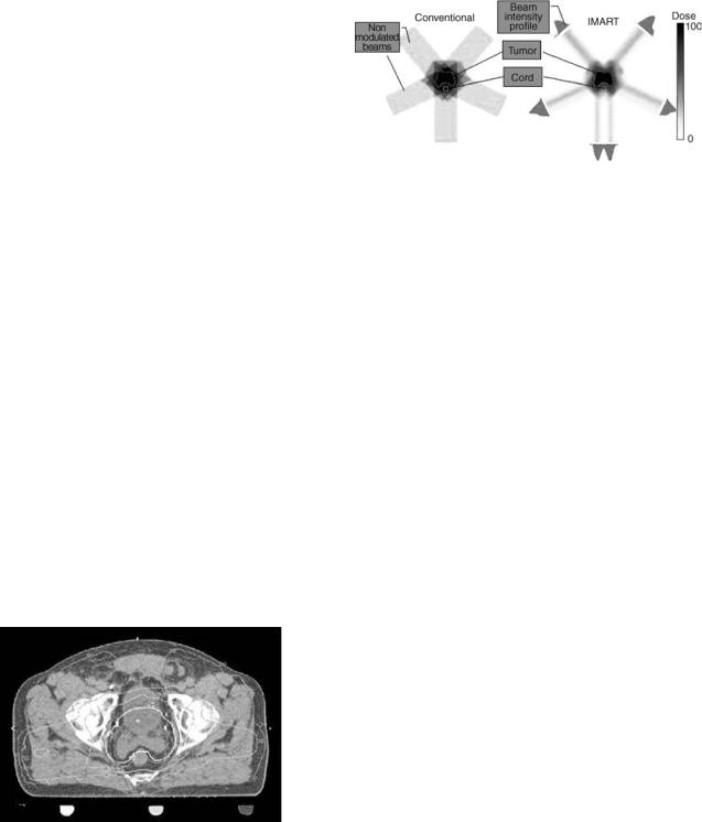
The methodology for designing radiation beams in a CT simulator introduced so far is quite straightforward. For example, with respect to a PTV, all beams are coplanar, and the intensity distribution within the field of each beam is constant. Furthermore, usually only two to three beams are engaged in treatment delivery. As shown in the left column of Fig. 9, such a very limited number of coplanar beams with uniform intensity distribution are generally
Figure 9. Schematic diagrams illustrates the mechanisms underlying conventional 3D conformal RT (a) and modern intensity modulated RT (b). The volume of the targeted tumor is concave, and the critical organ (spine cord) is within the concavity. The spine cord would undertake almost the same radiation dose as the target tumor volume if the conventional 3D conformal RT is administrated. However, with intensity modulation RT, the radiation dose to the spine cord can be substantially reduced to be below tolerable toxicity level. (Courtesy of Sabbe Mollio, Ph.D., University of California at Irvin.) Please see online for color figure.
COMPUTED TOMOGRAPHY SIMULATOR |
273 |
Figure 10. A CT image in transaxial plane shows a concave CTV outlined by the yellow boundary, the corresponding PTV contoured by the red boundary, and the nearby critical organ (spine cord) within the concavity. (Courtesy of Michelle Lee, Eleka AB.) Please see online version for color figure.
not able to conform a 3D target volume tightly, no matter how accurately the beam and its field are designed. Hence, the conventional 3D conformal radiation therapy is at most a coarse approximation to the ideal 3D conformity.
In reality, a targeted cancerous tumor can be much more complicated than just a regular and convex volume. For example, a target tumor can be irregular, concave with nearby normal critical organs or tissues within its cavity (see Fig. 10), or the targeted cancerous tumor even wraps itself around nearby normal organs or tissues. To make sure all cancerous tumors be included in a PTV, a physician has no choice but to take extra margins surrounding the identified CTV into account. Consequently, the PTV can be unfortunately quite large due to the conservative strategies exercised, resulting in an undesirable radiation dose to the surrounding normal organs or tissues, and significantly compromising the success of radiation therapy.
Given the complexity of the 3D shape of a targeted malignant tumor and its geometrical relationship with nearby normal structures, true 3D conformity is desired in RT to deliver the needed radiation dose accurately and avoid unnecessary damages to the cells of surrounding normal organs or tissues. Actually, the combination of the modern CT technology and 3D visualization methods has paved the way toward true 3D conformal radiation therapy. Aiming at improving the therapeutic index, tremendous efforts have been devoted in the radiation therapy community to exploring more effective RT solutions. What follows is a brief introduction to the exciting progresses made up to date.
Computed Tomography Simulation For Intensity Modulated
Radiation Therapy
One of the innovations over conventional 3D conformal RT is the so-called intensity modulated radiation therapy (IMRT) (30–33). The two primary differences between the IMRT and conventional 3D conformal RT are (a) beams do not have to be coplanar; (b) the radiation intensity distribution within a beam is not uniform. In practice, noncoplanar beams can be readily realized by horizontally rotating the patient couch of a treatment machine. With respect to beam intensity, there exist two ways to modulate the distribution. One way is to partition the beam field into a few subfields, and various radiation blockers, such as
274 COMPUTED TOMOGRAPHY SIMULATOR
wedge, partial blocker, or compensator, are employed to modulate the intensity of each subfield. Such an IMRT implementation is called the ‘‘step-and-shoot’’ mode. The other way is to move the leaves of a computer-controlled multileaf collimator dynamically and individually. The intensity distribution within each beam field is modulated by appropriately opening and shutting the leaves of a multileaf collimator. Such an implementation is called the ‘‘sliding window’’ mode, because each leaf of a multileaf collimator is continuously sliding during the treatment delivery. The radiation beams in these two modes can three-dimensionally encompass an identified target volume with improved conformity, and deliver a radiation dose distribution with a significantly improved accuracy than that allowed by the conventional 3D conformal radiation therapy, no matter how complicated the shape of the identified target volume is.
To illustrate the mechanism of 3D conformity in IMRT, the 2D in-plane conformity achieved by intensitymodulated coplanar beams is shown in the right column of Fig. 9, while the 3D conformity using noncoplanar intensity-modulated beams is not hard to deduce. As the conformity significantly is improved, either an escalated radiation dose can be delivered to the target volume at the same dose level absorbed by surrounding normal organs or tissues, or the same dose can be delivered to the target volume with less radiation toxicity to surrounding structures. It means that, IMRT not only conforms a high dose delivery to the targeted tumor volume, but also minimizes the radiation dose to the nearby structures.
To achieve an improved 3D conformity, the IMRT requires accurate 3D geometrical delineation of an identified target volume and its surrounding structures, beam orientation, field partition, intensity modulation via blockers, wedges, compensators, or a multileaf collimator. It is not difficult to imagine that, without the previously described functionalities offered by a CT-simulator, the implementation of IMRT would be out of the question. In fact, the dependence of the IMRT upon the CT simulator is so profound that the CT simulator is no longer separable from a radiation treatment planning system for which the IMRT is designed and verified. At present, the boundary between a CT simulator and a treatment planning system is fading. More and more radiation treatment planning systems are incorporating the functionalities that used to be provided by a stand-alone CT simulator as an integrated part in the IMRT-based 3D conformal radiation therapy.
With an improved 3D conformity, the success of the IMRT-based 3D conformal RT relies on the geometry accuracy and reproducibility to a significantly larger extent than that in conventional 3D conformal RT. Any geometry uncertainty (6) due to beam setup (mechanical and optical allowances), imperfect reproducibility, or organ motion induced errors can significantly compromise the outcome of the radiation therapy, as the intensity modulated beams conform the target volume very compactly. In addition to 3D conformity, the homogeneity of the dose distribution delivered to a target volume is also a requirement of a successful radiation therapy. However, with an emphasis on the 3D conformity, the dose homogeneity is usually compromised, posing more challenges to the RT process.
Meanwhile, the verification of the radiation dose distribution in IMRT becomes difficult, demanding much more complicated devices and phantoms to accomplish quality assurance (34,35). As a result, caution or discretion must be exercised in the clinic while a decision is being made on adopting IMRT for 3D conformal radiation therapy, although clinical reports showing favorable results of IMRT over conventional 3D conformal RT have been growing in the literature. In all fairness, not all cancer sites are suitable for the application of IMRT, and a general rule is that for a relatively regular target tumor, conventional 3D conformal RT is preferable, whereas IMRT is preferable in circumstances where the target tumor is irregular, concave with critical organs or tissues within the concavity, or even wraps itself around the nearby normal critical organs or tissues. Meanwhile, there may exist too much freedom in IMRT to conform an irregularly shaped target volume, leading to more difficulties in the optimization with respect to candidate treatment plans to achieve various objective functions while satisfying certain constraints. At present, numerous basic and clinical investigations are under way in the RT community to attain IMRT protocols for 3D conformal RT.
Computed Tomography Simulation For Tomotherapy
With the freedom in increasing the number of beams, specifying the beam shape and orientation, and modulating the beam intensity distribution, IMRT technology can be advanced even further (30,31). A more aggressive implementation of IMRT is the so-called tomotherapy (36–38). As implied by its name, tomotheraphy is inspired by the scanning mode of X-ray CT that has been extensively utilized in diagnostic imaging over the past three decades. Interestingly, the evolution of tomotherapy is similar to that of diagnostic CT. The geometry of an initial tomotherapy system is virtually the same as that of a single slice CT scanner prior to the introduction of helical–spiral CT. In such a tomotherapy system, the target volume is irradiated by a small fan beam moving along an arc trajectory (37). Consequently, the number of beams is increased dramatically while the field size of each beam is accordingly decreased. At each angular position, the radiation intensity of the small fan beam is dynamically modulated by a binary multileaf collimator that is driven pneumatically. In a ‘‘slice-by-slice’’ fashion, a target volume can be irradiated with a significantly improved 3D conformity, provided that the thickness of the small fan beam is sufficiently small. Similar to the CT evolution from the circular scanning mode to the helical–spiral scanning mode, tomotherapy has evolved into helical–spiral tomotherapy, in which the patient couch proceeds at a constant speed while the radiation source is rotated in the gantry around a patient (36,38). At each angular position, the intensity of the small fan beam is temporally modulated by a pneumatically driven multileaf collimator using an appropriate opening and shutting scheme. Through helical–spiral scanning, the radiation dose can conform a targeted volume very tightly, regardless of whether it is regular or irregular, concave or convex, delivering an adequate treatment dose to the targeted volume while depositing a minimum dose to the surrounding normal organs and tissues.
As in conventional IMRT, tomotherapy, either in the arc or the helical–spiral mode, requires an accurate geometrical delineation of a target volume and a reliable reproducibility of the patient positioning. The latest helical–spiral tomotherapy system has even evolved into an ‘‘all-in-one’’ system: a radiation therapy machine that includes all the needed modules: CT simulator, treatment planning, treatment delivery, as well as a real CT scanner (called tomoimage CT scanner) using therapeutic photons as the tomographic imaging means. Although its contrast resolution is significantly degraded in comparison to that of a diagnostic CT scanner or an RT-dedicated CT scanner, the tomoimage CT scanner can provide acceptable spatial resolution for accurate patient repositioning, playing a role of portal imaging, such as DRR, used in the conventional 3D conformal RT to assure geometry accuracy and reproducibility. With self-consistency among anatomic imaging, treatment planning, treatment delivery, and verification, such an ‘‘all-in-one’’ tomotherapy system can significantly improve the geometrical integrity, which is one of the most critical challenging tasks of IMRT (36,38).
Computed Tomography Simulation For Stereotactic
Radiosurgery
In addition to 3D conformal RT, a state-of-the-art stereotactic radiosurgery (39–41) also relies entirely on the capabilities of a CT simulator in which either protons or high energy X-ray photons are employed. Rather than being administrated in a fractionated manner, stereotactic radiosurgery is a one-session or ‘‘lump sum’’ radiation treatment delivery procedure just like a surgery operation. Because of single treatment delivery, the radiation intensity must be elevated to the highest tolerable degree, and such a greatly elevated radiation intensity can damage cells in surrounding normal organs or tissues. Hence, stereotactic radiosurgery is usually employed in the management of small (2–3 cm) cancerous tumors. Moreover, with a radiation intensity that is greatly larger than that of 3D conformal RT, stereotactic radiosurgery demands a much more accurate geometric delineation of targeted tumors, and any geometrical uncertainty due to patient position, immobilization, and organ motion could result in treatment disaster. Consequently, stereotactic radiosurgery is only employed to cure small tumor in patient’s head or neck, where patient immobilization devices can be applied reliably. In the early stage of stereotactic radiosurery, 2D imaging techniques, such as fluoroscopic angiography, were employed to identify target volumes and determine the number and orientation of radiation beams. Recently, similar to the evolution of 3D conformal RT, state-of-the-art stereotactic radiosurgery procedure increasingly rely on 3D patient data acquired by a CT scanner and the treatment planning in which the functionalities of a CT simulator are integrated.
THE FUTURE OF COMPUTED TOMOGRAPHY SIMULATOR
To achieve a full 3D conformity in radiation therapy, an ultimate solution would be the utilization of a very large
COMPUTED TOMOGRAPHY SIMULATOR |
275 |
number of pencil beams with their intensity being modulated instantly (42–44). However, a full 3D conformity demands perfect geometrical accuracy, since the dose gradient at the boundary of the 3D conformed target volume would be extremely sharp. Any geometrical uncertainties due to inaccurate patient position, unreliable immobilization, beam set up errors, misregistration between 3D patient data acquisition and treatment delivery, and particularly organ motion, could lead to treatment failure: underdosing-to-target volumes or overdosing to nearby normal critical organs or tissues, or both.
All the 3D conformal RT techniques introduced thus far are implemented in a ‘‘forward’’ way that is, once a set of 3D patient data is acquired, the simulation, treatment planning, planning verification, and delivery are implemented sequentially. In the forward mode, the simulation and treatment planning processes are conducted in a semiautomatic and iterative way with the involvement of radiation oncologists, physicists, therapists, and dosmetrists. To a great extent, the success of such a strategy is dependent on the experience or skill of the physicians engaged. Encouraged by the vigorous technological progresses made over the past three decades, it is believed that modern 3D conformal RT will continue progressing with the development of medical imaging and 3D visualization technologies: delivering treatment to target volumes with a full 3D conformity and adequate dose while surrounding normal structures are minimally damaged. It is not hard to imagine that future RT would not achieve an optimized solution if the treatment planning is only performed in the forward mode, because the parameter space to be exhaustively searched in the optimization process is really large.
Recognizing the complexity of modern IMRT, a more reasonable way to accomplish radiation treatment planning is to treat it as an inverse problem. Starting from specifications on a desirable radiation dose distribution and certain constraints, such as the avoidance of critical anatomic structures, inverse treatment planning can be performed based on a set of patient CT data with the help of a CT simulator (30,45). There exist two major tasks in the inverse treatment planning: (a) selection of an objective function and constraints; (b) development of an efficient algorithm to solve the optimization problem (46). A number of objective functions and constraints, such as dose (47), dose-volume (48,49), equivalent uniform dose (50,51), generalized equivalent dose (52), biological indices (53), and their combinations, have been proposed to date (54). Meanwhile, a few optimization approaches, such as simulated annealing (55), gradient (48), active set (56), genetic (57), maximum likelihood (58), dynamically penalized likelihood (59), and fuzzy logic (60) algorithms, have been investigated (54). It is underlined that inverse treatment planning is mathematically an ill-posed optimization problem, and that certain regularization techniques ought to be used in the optimization process (46). Considering the inhomogeneous dose distribution associated with a full 3D conformity, the simulation process for the inverse treatment planning is significantly different from that for the forward treatment planning, but the basic functionalities, such as target volume defining and 3D visualization of a CT simulator, are still the same. Currently, inverse radiation
276 COMPUTED TOMOGRAPHY SIMULATOR
treatment planning is still an open research and development area that has attracted the major attention of the RT community.
The ultimate solution to guarantee geometry accuracy and reproducibility is to track targeted volumes and their motion dynamically for a full 3D conformity during the radiation treatment delivery. A tracking process can be realized through gating techniques employing various mechanical or optical sensors while a patient is scanned by an RT dedicated CT scanner (61–63). This is related to the concept of four-dimensional (4D) CT, by which variation of a 3D model of a patient is revealed instantly. Such a 4D planning strategy can be implemented either offor online. In the off-line mode, a target volume and its surrounding normal organs or tissues are tracked by gating during the data acquisition by an RT-dedicated CT scanner, and the motion of the patient and organs are recorded and exported to a treatment machine for radiation delivery. In the on-line mode, a patient is scanned by an RT-dedicated CT scanner during the treatment delivery. Apparently, the on-line mode needs to integrate an RT-dedicated CT scanner into a treatment machine (64,65). It is believed that with the development of the 4D CT technology, the 3D conformal RT can be administrated in an adaptive and well-controlled manner, leading to a significantly improved therapeutic index.
The majority of simulation in treatment planning for RT is currently implemented based up on 3D patient datasets acquired by a CT scanner, because of its merits in data acquisition, image generation, superior spatial resolution, as well as the capability of estimating the electronic density for dose calculation and verification. In addition to CT scanners, other modern 3D imaging modalities, such as magnetic resonance imaging (MRI), positron emission tomography (PET), and ultrasonic imaging, can also be incorporated into a virtual simulator for 3D conformal RT. There is no doubt that, in the predictable future CT will remain the modality of chioce for 3D conformal RT. However, with the development of modern image registration and data fusion techniques, images acquired by MRI, PET, and ultrasound are becoming more and more relevant, suggesting chances for them to be utilized in 3D conformal RT. Finally, it should be pointed out that all the CT simulation and virtual simulation techniques we have covered in this article are also applicable for RT using other high energy particles, such as protons and neutrons (5).
BIBLIOGRAPHY
1.Wright K, et al. Field shaping selective protection in megavolt radiation therapy. Radiology 1959;72:101.
2.Tsien K. The application of automatic computing machines to radiation treatment planning. Br J Radiol 1955;28:432.
3.Reinstein Le, et al. A computer-assisted three-dimensional treatment planning system. Radiology 1978;127:259–264.
4.McShan DL, et al. A computerized three-dimensional treatment planning system utilizing interactive colour graphics. Br J Radiol 1979;52:478–481.
5.Smith Rp, Mckenna WG. The Basics of Radiation Therapy. In: Abeloff MD, et al. editors. Clinical Oncology 3rd ed. Elsevier; Churchill Livingstone: 2004.
6.Jones B, et al. United Kingdom radiation oncology 1 conference (UKRO 1): Accuracy and uncertainty in radiotherapy. Br J Radiol 2002;75:297–305.
7.Sherouse GW, et al. Virtual simulation: concept and implementation. The 9th International Conference of the use of computers in radiation therapy (ICCR). North Holland Publishing Co.; The Netherland: 1987.
8.Sherouse GW, Novins K, Chaney EL. Computation of digitally reconstructed radiographs for use in radiotherapy treatment design. Int J Radiat Oncol Biol Phys 1990;18:651–658.
9.Sherouse GW, Bourland JD, Reynolds K. Virtual simulation in the clinical setting: some practical considerations. Int J Radiat Oncol Biol Phys 1990;19:1059–1065.
10.Mutac S, et al. Quality assurance for computed-tomography simulators and the computed-tomography-simulation process: Report of the AAPM radiation therapy committee Task Group No. 66. Med Phys 2003;30:2762–2792.
11.Gerber RL, Purdy JA. Quality assurance procedures and performance testing for CT-simulators. In: Purdy JA, Starkschall G, editors. A Practical Guide to 3-D Planning and Conformal Radiation Therapy. Advanced Medical Publishing, Inc.; Middleton (WI): 1999.
12.Conway J, Robinson MH. CT virtual simulation. Br J Radiol 70 (Suppl.):1997;S106–S118.
13.Aird EGA, Conway J. CT simulation for radiotherapy treatment planning. Br J Radiol 2002;75:937–949.
14.Fraass B, et al. American Association of Physicists in Medicine Radiation Therapy Committee Task Group 53: Quality assurance for clinical radiotherapy treatment planning. Med Phys 1998;25:1773–1829.
15.Van Dyk J, Taylor JS. CT-simulators. In: Van Dyk J. editor. The Modern Technology for Radiation Oncology: A Compendium for Medical Physicists and Radiation Oncologists. Medical Physics Publishing; Madison (WI): 1999.
16.Kutcher GJ, et al. Comprehensive QA for radiation oncology: report of AAPM Radiation Therapy Committee Task Group 40. Med Phys 1994;21:581–618.
17.AAPM, Report No. 39. Specification and Acceptance Testing of Computed Tomography Scanners. American Institute of Physics; New York: 1993.
18.Kalender WA. Computed Tomography: Fundamentals, System Technology, Image Quality, Applications. 2nd ed. Wiley; New York: 2004.
19.Hsieh J. Computed Tomography: Principles, Design, Artifacts, and Recent Advances. SPIE Press; Bellingham (WA): 2003.
20.Wang G, Crawford CR, Kalender WA. Multi-row-detector and cone-beam spiral/helical CT. IEEE Trans Med Imag 2000; 19:922–929.
21.Tang X, Hsieh J. A filtered backprojection algorithm for cone beam reconstruction using rotational filtering under helical source trajectory. Med Phys 2004;31:2949–2960.
22.Tang X, Hsieh J, Nilsen RA, Dutta S. A helical cone beam filtered backprojection (CB-FBP) reconstruction algorithm using three-dimensional (3D) view weighting. SPIE Proc 2004;5535:577–587.
23.Langmack KA. Portal Imaging. Br J Radiol 2001;74:789–804.
24.Verrellen D, Linthout N, Berge DVD, Bel A, Storme G. Initial experience with intensity modulated therapy for treatment of the head and neck region. Int J Radio Oncol Bio Phys 1997;39:99–114.
25.Grant W, Woo SY. Clinical and financial issues for intensitymodulated radiation therapy delivery. Semin Radia Oncol 1999;9:99–107.
26.Korba A, et al. Pseudoblocks and portal localization. Radiology 1977;122:260–261.
27.Convery DJ, Rosenbloom ME. The generation of intensity modulated fields for conformal radiotherapy by dynamic collimation. Phys Med Biol 1992;37:48–59.