

- •Section 1 System Overview
- •1.1 System Description
- •1.2 Line Replaceable Units (LRU)
- •1.3 G1000 Controls
- •PFD/MFD Controls
- •Audio Panel Controls
- •1.4 Secure Digital (SD) Cards
- •1.5 System Power-up
- •1.6 System Operation
- •Normal Display Operation
- •Reversionary Display Operation
- •AHRS Operation
- •G1000 System Annunciations
- •Softkey Function
- •GPS Receiver Operation
- •1.7 Accessing G1000 Functionality
- •Menus
- •MFD Page Groups
- •MFD System Pages
- •Electronic Checklists (Optional)
- •1.8 Display Backlighting
- •Automatic Adjustment
- •Manual Adjustment
- •Section 2 flight Instruments
- •2.1 Flight Instruments
- •Airspeed Indicator
- •Attitude Indicator
- •Altimeter
- •Vertical Speed Indicator (VSI)
- •Vertical Deviation, Glideslope, & Glidepath Indicators
- •Horizontal Situation Indicator (HSI)
- •Course Deviation Indicator (CDI)
- •2.2 Supplemental Flight Data
- •Generic Timer
- •Outside Air Temperature
- •Wind Data
- •System Time
- •Vertical Navigation (VNV) Indications
- •2.3 PFD Annunciations and Alerting Functions
- •System Alerting
- •Traffic Annunciation
- •TAWS Annunciations
- •Low Altitude Annunciation
- •Altitude Alerting
- •Minimum Descent Altitude/Decision Height Alerting
- •Marker Beacon Annunciations
- •2.4 Abnormal Operations
- •Abnormal GPS Conditions
- •Unusual Attitudes
- •Section 3 Engine Indication System (EIS)
- •3.1 Engine Display
- •3.2 Lean Display
- •3.3 System Display
- •Section 4 audio panel and CNS
- •4.1 Overview
- •PFD/MFD Controls and Frequency Display
- •Audio Panel Controls
- •4.2 COM Operation
- •COM Transceiver Selection and Activation
- •COM Transceiver Manual Tuning
- •Quick-Tuning and Activating 121.500 MHz
- •Auto-tuning the COM Frequency
- •Frequency Spacing
- •Automatic Squelch
- •Volume
- •4.3 NAV Operation
- •NAV Radio Selection and Activation
- •NAV Receiver Manual Tuning
- •Auto-tuning the NAV Frequency
- •Marker Beacon Receiver
- •DME Tuning (Optional)
- •4.4 GTX 33 Mode S Transponder
- •Transponder Controls
- •Transponder Mode Selection
- •Entering a Transponder Code
- •IDENT Function
- •Flight ID Reporting
- •4.5 Additional Audio Panel Functions
- •Power-Up
- •Mono/Stereo Headsets
- •Speaker
- •Intercom
- •Clearance Recorder and Player
- •Entertainment Inputs
- •4.6 Audio Panel Preflight Procedure
- •4.7 Abnormal Operation
- •Stuck Microphone
- •COM Tuning Failure
- •Audio Panel Fail-Safe Operation
- •Reversionary Mode
- •Section 5 GPS Navigation
- •5.1 Introduction
- •5.2 Navigation Map (MFD)
- •Navigation Map Page
- •5.3 PFD Inset Map and Windows
- •Inset Map
- •PFD Windows
- •5.4 Direct-to-Navigation (MFD)
- •Selecting a Direct-to Waypoint
- •Clearing Vertical Constraints
- •Specifying a Course to a Waypoint
- •Canceling Direct-to Navigation
- •Direct-to Navigation Shortcuts
- •5.5 Direct-to-Navigation (PFD)
- •5.6 Airport Information (MFD)
- •Duplicate Waypoints
- •Additional Airport Runway Information
- •5.7 Intersection Information (MFD)
- •5.8 NDB Information (MFD)
- •5.9 VOR Information (MFD)
- •5.10 User Waypoint Information (MFD)
- •5.11 Nearest Airports (MFD)
- •5.12 Nearest Intersections (MFD)
- •5.13 Nearest NDB (MFD)
- •5.14 Nearest VOR (MFD)
- •5.15 Nearest User Waypoint (MFD)
- •5.16 Nearest Airspaces
- •5.17 Nearest Airports (PFD)
- •5.18 Flight Planning (MFD)
- •Airways/Jetways
- •Display of Airways on the Flight Plan Page
- •Vertical Navigation (VNV)
- •Navigating an Example Flight Plan
- •Parallel Track (PTK)
- •5.19 Flight Planning (PFD)
- •Operations
- •5.20 Procedures (MFD)
- •Leg Types Supported by the G1000
- •5.21 Procedures (PFD)
- •Operations
- •5.22 ABNORMAL OPERATION
- •Dead Reckoning
- •Section 6 Hazard Avoidance
- •6.1 XM Satellite Weather (Service Optional)
- •Activating XM Satellite Services
- •Using XM SATELLITE Weather Products
- •Weather Softkeys on the Weather Data Link Page
- •Setting Up the Weather Data Link Page
- •XM Satellite Weather on the Navigation Map
- •6.2 WX-500 Stormscope (Optional)
- •Setting Up Stormscope on the Navigation Map
- •Selecting the Stormscope Page
- •6.3 Terrain Proximity
- •Requirements
- •GPS Position and GPS-MSL Altitude
- •Displaying Terrain Proximity Data
- •Terrain Proximity Symbols
- •Terrain Proximity Page
- •Navigation Map Page
- •6.4 TAWS (Optional)
- •Requirements
- •TAWS Alerting
- •Using TAWS
- •TAWS Symbols
- •TAWS Alerts
- •6.5 Traffic
- •Traffic Information Service (TIS)
- •Honeywell KTA 870 TAS System (Optional)
- •ADS-B Traffic (Optional)
- •Section 7 Automatic Flight Control System
- •7.1 AFCS Controls
- •7.2 Flight Director Operation
- •Command Bars
- •Activating the Flight Director
- •7.3 Flight Director Modes
- •Pitch Modes
- •Roll Modes
- •7.4 Autopilot Operation
- •Engaging the Autopilot
- •Control Wheel Steering
- •Disengaging the Autopilot
- •7.5 Example Procedures
- •Departure
- •Intercepting a VOR Radial
- •Flying a Flight Plan/GPS Course
- •Descent
- •Approach
- •Go Around/Missed Approach
- •7.6 AFCS Annunciations and Alerts
- •AFCS Status Alerts
- •Overspeed Protection
- •Section 8 Additional Features
- •8.1 SafeTaxi
- •SafeTaxi Cycle Number and Revision
- •8.2 ChartView
- •ChartView Softkeys
- •Terminal Procedures Charts
- •Chart Options
- •Day/Night View
- •ChartView Cycle Number and Expiration Date
- •8.3 FliteCharts
- •FliteCharts Softkeys
- •Terminal Procedures Charts
- •Chart Options
- •Day/Night View
- •FliteCharts Cycle Number and Expiration Date
- •8.4 XM Radio Entertainment (Optional)
- •XM Satellite Radio Service
- •XM Service Activation
- •Using XM Radio
- •Automatic Audio Muting
- •8.5 Abnormal Operation
- •Annunciations and Alerts
- •Alert Level Definitions
- •NAV III Aircraft Alerts
- •CO Guardian Messages
- •G1000 System Annunciations
- •Other G1000 Aural Alerts
- •G1000 System Message Advisories
- •AFCS Alerts
- •TAWS ALERTS
- •TAWS System Status Annunciations
- •SD Card Use
- •Jeppesen Databases
- •Garmin Databases
- •Glossary
- •Frequently Asked Questions
- •General TIS Information
- •Introduction
- •TIS vs. TAS/TCAS
- •TIS Limitations
- •Map Symbols
- •Index

APPENDIX A
ANNUNCIATIONS AND ALERTS
 NOTE: The Cessna aircraft Pilot’s Operating Handbook (POH) supersedes information found in this document.
The G1000 Alerting System conveys alerts to the pilot using a combination of the following items:
•Annunciation Window: The Annunciation Window displays abbreviated annunciation text. Text color is based on alert levels described later in the Alert Levels Definitions section. The Annunciation Window is located to the right of the Altimeter and Vertical Speed Indicator on the display. All Cessna Nav III annunciations can be displayed simultaneously in the Annunciation Window. A white horizontal line separates annunciations that are acknowledged from annunciations that are not yet acknowledged. Higher priority annunciations are displayed towards the top of the window. Lower priority annunciations are displayed towards the bottom of the window.
•Alerts Window: The Alerts Window displays alert text messages. Up to 64 prioritized alert messages can be displayed in the Alerts Window. Pressing the ALERTSSoftkey displays the Alerts Window. Pressing the ALERTS Softkey a second time removes the Alerts Window from the display. When the Alerts Window is displayed, the pilot can use the large FMS Knob to scroll through the alert message list.
•Softkey Annunciation: During certain alerts, the ALERTS Softkey may appear as a flashing annunciation to accompany an alert. The ALERTS Softkey assumes a new label consistent with the alert level (WARNING, CAUTION, or ADVISORY). By pressing the softkey annunciation, the pilot acknowledges awareness of the alert. The softkey then returns to the previous ALERTS label. If alerts are still present, the ALERTS label will be displayed in inverse video (white background with black text). The pilot can press the ALERTS Softkey a second time to view alert text messages.
•SystemAnnunciations: Typically,alargered‘X’appearsinwindowswhenafailureisdetectedintheLRUproviding the information to the window. See the G1000 System Annunciations section for more information.
•Audio Alerting System: The G1000 system issues audio alert tones when specific system conditions are met. See the Alert Levels Definitions section for more information.
System
Annunciation
Red ‘X’
Annunciation
Window
Alerts Window
ALERTS Softkey
Annunciation
Figure A-1 G1000 Alerting System
190-00498-02 Rev.A |
Garmin G1000 Pilot’s Guide for Cessna Nav III |
A-1 |

APPENDIX A
ALERT LEVEL DEFINITIONS
The G1000 Alerting System, as installed in Cessna Nav III aircraft, uses three alert levels.
•WARNING: This level of alert requires immediate pilot attention. A warning alert is annunciated in the Annunciation Window and is accompanied by a continuous aural tone. Text appearing in the Annunciation Window is RED. A warning alert is also accompanied by a flashing WARNING Softkey annunciation, as shown in Figure A-2. Pressing the WARNING Softkey acknowledges the presence of the warning alert and stops the aural tone, if applicable.
•CAUTION: This level of alert indicates the existence of abnormal conditions on the aircraft that may require pilotintervention. AcautionalertisannunciatedintheAnnunciationWindowandisaccompaniedbyasingle aural tone. Text appearing in the Annunciation Window is YELLOW. A caution alert is also accompanied by a flashing CAUTION Softkey annunciation, as shown in Figure A-3. Pressing the CAUTION Softkey acknowledges the presence of the caution alert.
•MESSAGE ADVISORY: This level of alert provides general information to the pilot. A message advisory alert does not issue annunciations in the Annunciation Window. Instead, message advisory alerts only issue a flashing ADVISORY Softkey annunciation, as shown in Figure A-4. Pressing the ADVISORY Softkey acknowledges the presence of the message advisory alert and displays the alert text message in the Alerts Window.
Figure A-2 WARNING Softkey |
Figure A-3 CAUTION Softkey |
Figure A-4 ADVISORY Softkey |
Annunciation |
Annunciation |
Annunciation |
NAV III AIRCRAFT ALERTS
The following alerts are configured specifically for the Cessna Nav III aircraft. See the Cessna Pilot’s Operating Handbook (POH) for information regarding pilot responses.
WARNING ALERTS
Annunciation Window Text |
Audio Alert |
OIL PRESSURE |
Continuous Aural Tone |
LOW VOLTS |
Continuous Aural Tone* |
|
|
HIGH VOLTS |
Continuous Aural Tone |
CO LVL HIGH |
Continuous Aural Tone |
PITCH TRIM** |
No Tone |
|
|
* Aural tone is inhibited while the aircraft is on the ground ** KAP 140 installations only
A-2 |
Garmin G1000 Pilot’s Guide for Cessna Nav III |
190-00498-02 Rev.A |
APPENDIX A
CAUTION ALERTS
Annunciation Window Text |
Audio Alert |
LOW VACUUM |
Single Aural Tone |
LOW FUEL L |
Single Aural Tone |
LOW FUEL R |
Single Aural Tone |
STBY BATT |
Single Aural Tone |
CAUTION ALERTS (T182,T206,AND 206 WITH PROP DE-ICE ONLY)
Annunciation Window Text |
Audio Alert |
PROP HEAT |
Single Aural Tone |
SAFE OPERATING ANNUNCIATION (T182,T206,AND 206 WITH PROP DE-ICE ONLY)
|
Annunciation Window Text |
Audio Alert |
|
|
|
PROP HEAT |
No Tone |
|
|
CO GUARDIAN MESSAGES |
|
|
||
|
|
|
|
|
|
Alerts Window Message |
|
Comments |
|
|
CO DET SRVC – The carbon |
|
There is a problem within |
|
|
monoxide detector needs |
|
the CO Guardian that |
|
|
service. |
|
requires services. |
|
|
CO DET FAIL – The carbon |
|
Loss of communication |
|
|
monoxide detector is inopera- |
|
between the G1000 and |
|
|
tive. |
|
the CO Guardian. |
|
G1000 SYSTEM ANNUNCIATIONS
When a new alert is issued, the ALERT Softkey will flash to alert the pilot of a new message. It will continue to flash until acknowledged by pressing the softkey. Active alerts are displayed in white text. Alerts that have become inactive will change to gray text. The ALERT Softkey will flash if the state of a displayed alert changes or a new alert is displayed. The inactive alerts can be removed from the Alert Window by pressing the flashing ALERT Softkey.
The G1000 System Messages convey messages to the pilot regarding problems with the G1000 system. When an LRU or an LRU function fails, a large red ‘X’ is typically displayed on windows associated with the failed data. The following section describes various system annunciations. Refer to the POH for additional information regarding pilot responses to these annunciations.
190-00498-02 Rev.A |
Garmin G1000 Pilot’s Guide for Cessna Nav III |
A-3 |
APPENDIX A
 NOTE: Upon power-up of the G1000 system, certain windows remain invalid as G1000 equipment begins to initialize. All windows should be operational within one minute of power-up. Should any window continue to remain flagged, the G1000 system should be serviced by a Garmin-authorized repair facility.
GIA 63/W |
|
|
|
|
|
|
|
|
|
|
|
|
|
|
|
GIA 63/W |
||||
|
|
|
|
|
|
|
|
|
|
|
|
|
||||||||
Integrated |
|
|
|
|
|
|
|
|
|
Integrated |
||||||||||
Avionics Units |
|
|
|
|
|
|
|
|
|
Avionics Units |
||||||||||
|
|
|
|
|
|
|
|
|
|
|
|
|
|
|
|
|
|
|
|
GDC 74A Air |
|
|
|
|
|
|
|
|
|
|
|
|
|
|
|
|
|
|
|
|
|
|
|
|
|
|
|
|
|
|
|
|
|
|
|
|
|
|
|
|
|
Data Computer |
|
|
|
|
|
|
|
|
|
|
|
|
|
|
|
|
|
|
|
|
GRS 77 AHRS |
|
|
|
|
|
|
|
|
|
|
|
|
|
|
|
|
|
|
|
|
|
|
|
|
|
|
|
|
|
|
|
|
|
|
|
|
|
|
|
|
|
|
|
|
|
|
|
|
|
|
|
|
|
|
|
|
|
|
|
|
|
|
|
GEA 71 Engine |
|
|
|
|
|
|
|
|
|
|
|
|
|
OR |
||||||
|
|
|
|
|
|
|
|
|
|
|
|
|
|
|
|
|
|
|||
Airframe Unit |
|
|
|
|
|
|
|
|
|
|
|
|
GMU 44 |
|||||||
OR |
|
|
|
|
|
|
|
|
|
|
|
|
Magnetometer |
|||||||
GIA 63/W |
|
|
|
|
|
|
|
|
|
|
|
|
|
|
|
|||||
|
|
|
|
|
|
|
|
|
|
|
|
|||||||||
Integrated |
|
|
|
|
|
|
|
|
|
|
|
|
|
|||||||
Avionics Unit |
|
|
|
|
|
|
|
|
|
|
|
|
|
|||||||
|
|
|
|
|
|
|
|
|
|
|
|
|
|
|
|
|
|
|
|
GIA 63/W Integrated |
|
|
|
|
|
|
|
|
|
|
|
|
|
|
|
|
|
|
|
|
|
|
|
|
|
|
|
|
|
|
|
|
|
|
|
|
|
|
|
|
|
Avionics Units |
|
|
|
|
|
|
|
|
|
|
|
|
|
|
|
|
|
|
|
|
GTX 33 Transponder |
|
|
|
|
|
|
|
|
|
|
|
|
|
|
|
|
|
|
|
|
|
|
|
|
|
GDC 74A Air |
|
|
|
|
|
|
|
|
|
|
|
|||||
|
|
|
|
|
|
|
|
|
|
|
|
|
|
|
||||||
|
|
|
|
|
|
|
|
|
|
|
|
|
|
|
||||||
|
|
|
|
|
|
|
|
|
|
|
|
|
|
|
OR |
|||||
|
|
|
|
Data Computer |
|
|
|
|
|
|
|
|
|
|||||||
|
|
|
|
|
|
|
|
|
|
|
|
|
GIA 63/W Integrated |
|||||||
|
|
|
|
|
|
|
|
Figure A-5 |
G1000 System Failure Annunciations |
|
|
|
|
|
||||||
|
|
|
|
|
|
|
|
|
|
|
|
|
Avionics Units |
|||||||
|
|
|
|
|
|
|
|
|
|
|
|
|
|
|
|
|
|
|
|
|
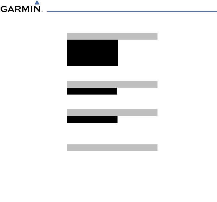
NOTE: Upon power-up,certain windows remain invalid as G1000 equipment begins to initialize. All windows should be operational within one minute of power-up. If any window continues to remain flagged, the G1000 System should be serviced by a Garmin-authorized repair facility.
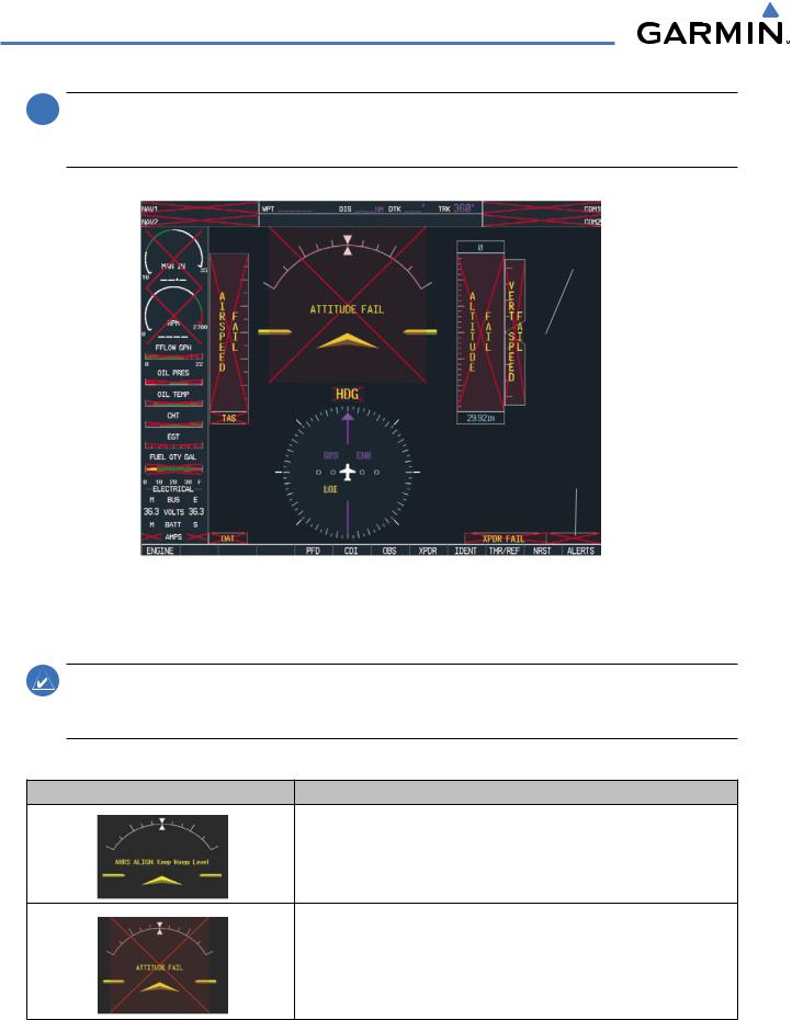
System Annunciation |
Comment |
Attitude and Heading Reference System is aligning.
Display system is not receiving attitude information from the AHRS.
A-4 |
Garmin G1000 Pilot’s Guide for Cessna Nav III |
190-00498-02 Rev.A |

APPENDIX A
System Annunciation |
Comment |
Indicates a configuration module failure.
This annunciation will only be seen when the autopilot is engaged. The annunciation indicates an AHRS monitor has detected an abnormal flight parameter, possibly caused by strong turbulence. In this case, the situation should correct itself within a few seconds. If there is an actual failure, a red “X” will soon appear over the Attitude Indicator.
Display system is not receiving airspeed input from air data computer.
Display is not receiving altitude input from the air data computer.
Display is not receiving vertical speed input from the air data computer.
|
Display is not receiving valid heading input from AHRS. |
|
|
|
|
|
‘LOI’ Indicates Loss of Integrity of GPS information. GPS information is either not |
|
|
present or is invalid for navigation use. ‘DR’ may also be seen indicating that GPS |
|
|
is in Dead Reckoning Mode. Note that AHRS utilizes GPS inputs during normal |
|
|
operation. AHRS operation may be degraded if GPS signals are not present (see |
|
|
AFMS). |
|
|
|
|
|
Display is not receiving valid transponder information. |
|
|
|
|
Other Various Red X Indications |
A red ‘X’ through any other display field, such as engine instrumentation fields, |
|
indicates that the field is not receiving valid data. |
||
|
190-00498-02 Rev.A |
Garmin G1000 Pilot’s Guide for Cessna Nav III |
A-5 |