


AUDIO PANEL AND CNS
4.4 GTX 33 MODE S TRANSPONDER
The GTX 33 Mode S Transponder provides Mode A, Mode C, and Mode S interrogation and reply capabilities. Selective addressing or Mode Select (Mode S) capability includes the following features:
•Level-2 reply data link capability (used to exchange information between aircraft and ATC facilities)
•Surveillance identifier capability
•Flight ID (Flight Identification) reporting – The Mode S Transponder reports aircraft identification as either the aircraft registration or a unique Flight ID.
•Altitude reporting
•Airborne status determination
•Transponder capability reporting
•Mode S Enhanced Surveillance (EHS) requirements
•Acquisition squitter – Acquisition squitter, or short squitter, is the transponder 24-bit identification address. The transmission is sent periodically, regardless of the presence of interrogations. The purpose of acquisition squitter is to enable Mode S ground stations and aircraft equipped with a Traffic Avoidance System (TAS) to recognize the presence of Mode S-equipped aircraft for selective interrogation.
The Hazard Avoidance Section provides more details on traffic avoidance systems.
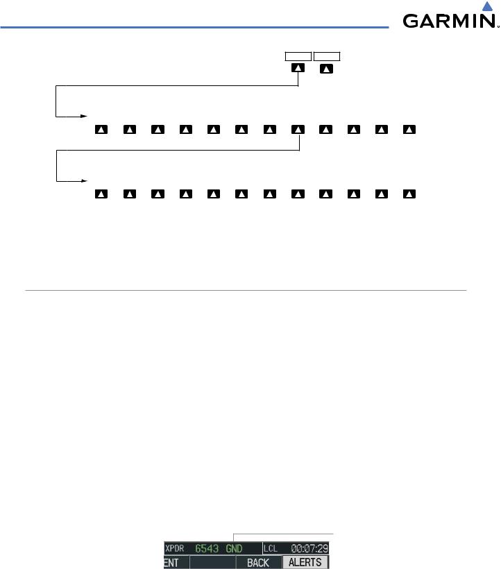
TRANSPONDER CONTROLS
Transponder function is displayed on three levels of softkeys on the PFD: Top-level, Mode Selection, and Code Selection. When the top-level XPDR Softkey is pressed, the Mode Selection softkeys appear: STBY, ON,
ALT, VFR, CODE, IDENT, BACK.
When the CODE Softkey is pressed, the number softkeys appear: 0, 1, 2, 3, 4, 5, 6, 7, IDENT, BKSP, BACK. The digits 8 and 9 are not used for code entry. Pressing the numbered softkeys in sequence enters the transponder code. If an error is made, pressing the BKSP Softkey moves the code selection cursor to the previous digit. Pressing the BKSP Softkey again moves the cursor to the next previous digit.
Pressing the BACK Softkey during code selection reverts to the Mode Selection Softkeys. Pressing the BACK Softkey during mode selection reverts to the top-level softkeys.
The code can also be entered with the FMS Knob. Code entry must be completed with either the softkeys or the FMS Knob, but not a combination of both.
Pressing the IDENT Softkey while in Mode or Code Selection initiates the ident function and reverts to the top-level softkeys.
After 45 seconds of transponder softkey inactivity, the system reverts back to the top-level softkeys.
190-00498-02 Rev A |
Garmin G1000 Pilot’s Guide for Cessna Nav III |
4-25 |
AUDIO PANEL AND CNS
XPDR IDENT
|
|
|
|
STBY |
ON |
ALT |
|
GND |
|
VFR |
|
CODE |
IDENT |
|
BACK |
ALERTS |
|
|
|
|
|
|
|
|
|
|
|
|
|
Pressing the IDENT or BACK Softkey |
|||
|
|
|
|
|
|
|
|
|
|
|
|
|
returns to the top-level softkeys. |
|||
|
|
|
|
|
|
|
|
|
|
|
|
|
|
|||
0 |
|
1 |
|
2 |
3 |
4 |
|
5 |
|
6 |
|
7 |
IDENT |
BKSP |
BACK |
ALERTS |
|
|
|
|
|
|
|
|
Pressing the IDENT Softkey returns to the top-level softkeys. |
||||||||
|
|
|
|
|
|
|
|
Pressing the BACK Softkey returns to the mode selection softkeys. |
||||||||
Figure 4-30 Transponder Softkeys (PFD)
TRANSPONDER MODE SELECTION
Modeselectioncanbeautomatic(GroundandAltitudeModes)ormanual(Standby,ON,andAltitudeModes). The STBY, ON, and ALT Softkeys can be accessed by pressing the XPDR Softkey.
Selecting a transponder mode:
1)Press the XPDR Softkey to display the Transponder Mode Selection Softkeys.
2)Press the desired softkey to activate the transponder mode.
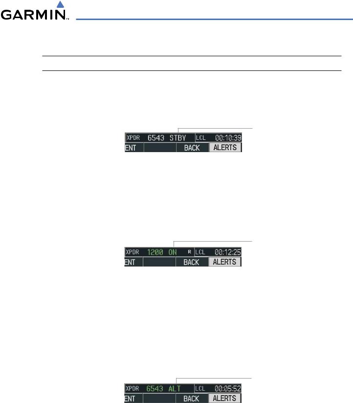
GROUND MODE
Ground Mode is normally selected automatically when the aircraft is on the ground. The transponder powers up in the last mode it was in when shut down. Ground Mode can be overridden by pressing any one of the Mode Selection Softkeys. A green ‘GND’ indication and transponder code appear in the mode field of the Transponder Data Box. In Ground Mode, the transponder does not allow Mode A and Mode C replies, but it does permit acquisition squitter and replies to discretely addressed Mode S interrogations.
When Standby Mode has been selected on the ground, the transponder can be returned to Ground Mode by pressing the GND Softkey.
GND
Mode
Figure 4-31 Ground Mode
4-26 |
Garmin G1000 Pilot’s Guide for Cessna Nav III |
190-00498-02 Rev A |
AUDIO PANEL AND CNS
STANDBY MODE (MANUAL)
 NOTE: In Standby Mode, the IDENT function is inoperative.
Standby Mode can be selected at any time by pressing the STBY Softkey. In Standby, the transponder does not reply to interrogations, but new codes can be entered. When Standby is selected, a white ‘STBY’ indication and transponder code appear in the mode field of the Transponder Data Box. In all other modes, these fields appear in green.
STBY Mode (White
Code Number and
Mode)
Figure 4-32 Standby Mode
MANUAL ON MODE
ON Mode can be selected at any time by pressing the ON Softkey. ON Mode generates Mode A and Mode S replies, but Mode C altitude reporting is inhibited. In ON Mode, a green ‘ON’ indication and transponder code appear in the mode field of the Transponder Data Box.
ON Mode
(No Altitude
Reporting)
Figure 4-33 ON Mode
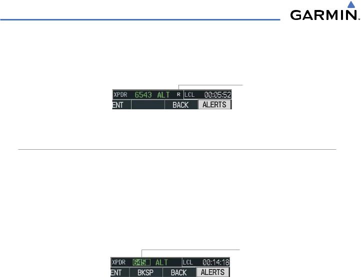
ALTITUDE MODE (AUTOMATIC OR MANUAL)
Altitude Mode is automatically selected when the aircraft becomes airborne. Altitude Mode may also be selected manually by pressing the ALT Softkey.
If Altitude Mode is selected, a green ‘ALT’ indication and transponder code appear in the mode field of the Transponder Data Box, and all transponder replies requesting altitude information are provided with pressure altitude information.
ALT Mode
(Mode C Altitude
Reporting)
Figure 4-34 Altitude Mode
190-00498-02 Rev A |
Garmin G1000 Pilot’s Guide for Cessna Nav III |
4-27 |
AUDIO PANEL AND CNS
REPLY STATUS
When the transponder sends replies to interrogations, a white ‘R’ indication appears momentarily in the reply status field of the Transponder Data Box.
Reply to
Interrogation
Figure 4-35 Reply Indication
ENTERING A TRANSPONDER CODE
Entering a transponder code with softkeys:
1)Press the XPDR Softkey to display the Transponder Mode Selection Softkeys.
2)Press the CODE Softkey to display the Transponder Code Selection Softkeys, for digit entry.
3)Press the digit softkeys to enter the code in the code field. When entering the code,the next softkey in sequence must be pressed within 10 seconds, or the entry is cancelled and restored to the previous code. Pressing the BKSP Softkey moves the code selection cursor to the previous digit. Five seconds after the fourth digit has been entered, the transponder code becomes active.
Entering
a Code
Figure 4-36 Entering a Code
4-28 |
Garmin G1000 Pilot’s Guide for Cessna Nav III |
190-00498-02 Rev A |
AUDIO PANEL AND CNS
Entering a transponder code with the PFD FMS Knob:
1)Press the XPDR and the CODE Softkeys as in the previous procedure to enable code entry.
2)Turn the small FMS Knob on the PFD to enter the first two code digits.
3)Turn the large FMS Knob to move the cursor to the next code field.
4)Enter the last two code digits with the small FMS Knob.
5)Press the ENT Key to complete code digit entry.
Pressing the CLR Key or small FMS Knob before code entry is complete cancels code entry and restores the previous code. Waiting for 10 seconds after code entry is finished activates the code automatically.
Turn the Small
FMS Knob to
Enter Two Code
Digits at a Time
Figure 4-37 Entering a Code with the FMS Knob
Press the ENT Key to Complete Code Entry
Turn the Large FMS Knob
to Move the Cursor to the Next Code Field
VFR CODE
The VFR code can be entered either manually or by pressing the XPDR Softkey, then the VFR Softkey. When the VFR Softkey is pressed, the pre-programmed VFR code is automatically displayed in the code field of the Transponder Data Box. Pressing the VFR Softkey again restores the previous identification code.
The pre-programmed VFR Code is set at the factory to 1200. If a VFR code change is required, contact a Garmin-authorized service center for configuration.
VFR Code
Figure 4-38 VFR Code
190-00498-02 Rev A |
Garmin G1000 Pilot’s Guide for Cessna Nav III |
4-29 |