

- •Section 1 System Overview
- •1.1 System Description
- •1.2 Line Replaceable Units (LRU)
- •1.3 G1000 Controls
- •PFD/MFD Controls
- •Audio Panel Controls
- •1.4 Secure Digital (SD) Cards
- •1.5 System Power-up
- •1.6 System Operation
- •Normal Display Operation
- •Reversionary Display Operation
- •AHRS Operation
- •G1000 System Annunciations
- •Softkey Function
- •GPS Receiver Operation
- •1.7 Accessing G1000 Functionality
- •Menus
- •MFD Page Groups
- •MFD System Pages
- •Electronic Checklists (Optional)
- •1.8 Display Backlighting
- •Automatic Adjustment
- •Manual Adjustment
- •Section 2 flight Instruments
- •2.1 Flight Instruments
- •Airspeed Indicator
- •Attitude Indicator
- •Altimeter
- •Vertical Speed Indicator (VSI)
- •Vertical Deviation, Glideslope, & Glidepath Indicators
- •Horizontal Situation Indicator (HSI)
- •Course Deviation Indicator (CDI)
- •2.2 Supplemental Flight Data
- •Generic Timer
- •Outside Air Temperature
- •Wind Data
- •System Time
- •Vertical Navigation (VNV) Indications
- •2.3 PFD Annunciations and Alerting Functions
- •System Alerting
- •Traffic Annunciation
- •TAWS Annunciations
- •Low Altitude Annunciation
- •Altitude Alerting
- •Minimum Descent Altitude/Decision Height Alerting
- •Marker Beacon Annunciations
- •2.4 Abnormal Operations
- •Abnormal GPS Conditions
- •Unusual Attitudes
- •Section 3 Engine Indication System (EIS)
- •3.1 Engine Display
- •3.2 Lean Display
- •3.3 System Display
- •Section 4 audio panel and CNS
- •4.1 Overview
- •PFD/MFD Controls and Frequency Display
- •Audio Panel Controls
- •4.2 COM Operation
- •COM Transceiver Selection and Activation
- •COM Transceiver Manual Tuning
- •Quick-Tuning and Activating 121.500 MHz
- •Auto-tuning the COM Frequency
- •Frequency Spacing
- •Automatic Squelch
- •Volume
- •4.3 NAV Operation
- •NAV Radio Selection and Activation
- •NAV Receiver Manual Tuning
- •Auto-tuning the NAV Frequency
- •Marker Beacon Receiver
- •DME Tuning (Optional)
- •4.4 GTX 33 Mode S Transponder
- •Transponder Controls
- •Transponder Mode Selection
- •Entering a Transponder Code
- •IDENT Function
- •Flight ID Reporting
- •4.5 Additional Audio Panel Functions
- •Power-Up
- •Mono/Stereo Headsets
- •Speaker
- •Intercom
- •Clearance Recorder and Player
- •Entertainment Inputs
- •4.6 Audio Panel Preflight Procedure
- •4.7 Abnormal Operation
- •Stuck Microphone
- •COM Tuning Failure
- •Audio Panel Fail-Safe Operation
- •Reversionary Mode
- •Section 5 GPS Navigation
- •5.1 Introduction
- •5.2 Navigation Map (MFD)
- •Navigation Map Page
- •5.3 PFD Inset Map and Windows
- •Inset Map
- •PFD Windows
- •5.4 Direct-to-Navigation (MFD)
- •Selecting a Direct-to Waypoint
- •Clearing Vertical Constraints
- •Specifying a Course to a Waypoint
- •Canceling Direct-to Navigation
- •Direct-to Navigation Shortcuts
- •5.5 Direct-to-Navigation (PFD)
- •5.6 Airport Information (MFD)
- •Duplicate Waypoints
- •Additional Airport Runway Information
- •5.7 Intersection Information (MFD)
- •5.8 NDB Information (MFD)
- •5.9 VOR Information (MFD)
- •5.10 User Waypoint Information (MFD)
- •5.11 Nearest Airports (MFD)
- •5.12 Nearest Intersections (MFD)
- •5.13 Nearest NDB (MFD)
- •5.14 Nearest VOR (MFD)
- •5.15 Nearest User Waypoint (MFD)
- •5.16 Nearest Airspaces
- •5.17 Nearest Airports (PFD)
- •5.18 Flight Planning (MFD)
- •Airways/Jetways
- •Display of Airways on the Flight Plan Page
- •Vertical Navigation (VNV)
- •Navigating an Example Flight Plan
- •Parallel Track (PTK)
- •5.19 Flight Planning (PFD)
- •Operations
- •5.20 Procedures (MFD)
- •Leg Types Supported by the G1000
- •5.21 Procedures (PFD)
- •Operations
- •5.22 ABNORMAL OPERATION
- •Dead Reckoning
- •Section 6 Hazard Avoidance
- •6.1 XM Satellite Weather (Service Optional)
- •Activating XM Satellite Services
- •Using XM SATELLITE Weather Products
- •Weather Softkeys on the Weather Data Link Page
- •Setting Up the Weather Data Link Page
- •XM Satellite Weather on the Navigation Map
- •6.2 WX-500 Stormscope (Optional)
- •Setting Up Stormscope on the Navigation Map
- •Selecting the Stormscope Page
- •6.3 Terrain Proximity
- •Requirements
- •GPS Position and GPS-MSL Altitude
- •Displaying Terrain Proximity Data
- •Terrain Proximity Symbols
- •Terrain Proximity Page
- •Navigation Map Page
- •6.4 TAWS (Optional)
- •Requirements
- •TAWS Alerting
- •Using TAWS
- •TAWS Symbols
- •TAWS Alerts
- •6.5 Traffic
- •Traffic Information Service (TIS)
- •Honeywell KTA 870 TAS System (Optional)
- •ADS-B Traffic (Optional)
- •Section 7 Automatic Flight Control System
- •7.1 AFCS Controls
- •7.2 Flight Director Operation
- •Command Bars
- •Activating the Flight Director
- •7.3 Flight Director Modes
- •Pitch Modes
- •Roll Modes
- •7.4 Autopilot Operation
- •Engaging the Autopilot
- •Control Wheel Steering
- •Disengaging the Autopilot
- •7.5 Example Procedures
- •Departure
- •Intercepting a VOR Radial
- •Flying a Flight Plan/GPS Course
- •Descent
- •Approach
- •Go Around/Missed Approach
- •7.6 AFCS Annunciations and Alerts
- •AFCS Status Alerts
- •Overspeed Protection
- •Section 8 Additional Features
- •8.1 SafeTaxi
- •SafeTaxi Cycle Number and Revision
- •8.2 ChartView
- •ChartView Softkeys
- •Terminal Procedures Charts
- •Chart Options
- •Day/Night View
- •ChartView Cycle Number and Expiration Date
- •8.3 FliteCharts
- •FliteCharts Softkeys
- •Terminal Procedures Charts
- •Chart Options
- •Day/Night View
- •FliteCharts Cycle Number and Expiration Date
- •8.4 XM Radio Entertainment (Optional)
- •XM Satellite Radio Service
- •XM Service Activation
- •Using XM Radio
- •Automatic Audio Muting
- •8.5 Abnormal Operation
- •Annunciations and Alerts
- •Alert Level Definitions
- •NAV III Aircraft Alerts
- •CO Guardian Messages
- •G1000 System Annunciations
- •Other G1000 Aural Alerts
- •G1000 System Message Advisories
- •AFCS Alerts
- •TAWS ALERTS
- •TAWS System Status Annunciations
- •SD Card Use
- •Jeppesen Databases
- •Garmin Databases
- •Glossary
- •Frequently Asked Questions
- •General TIS Information
- •Introduction
- •TIS vs. TAS/TCAS
- •TIS Limitations
- •Map Symbols
- •Index

HAZARD AVOIDANCE
SETTING UP THE WEATHER DATA LINK PAGE
The display of weather data on the Weather Data Link Page can be set up and customized by using the Data Link Menu (Figure 6-32). Weather legends for all active products can also be accessed from the Data Link Menu.
Figure 6-32 Data Link Menu
Figure 6-33 shows the Data Link Setup Window. The ‘ON’ and ‘OFF’ settings control the display of weather products the same way that softkeys do.
Winds Aloft
Data Selected
Figure 6-33 Data Link Setup Window
6-24 |
Garmin G1000 Pilot’s Guide for Cessna Nav III |
190-00498-02 Rev.A |

HAZARD AVOIDANCE
The selected range settings on the Data Link Setup Window control the largest map range at which each weather product displays on the Weather Data Link Page. Table 6-3 lists every map range option for all XM Satellite Weather products.
Data |
|
|
|
|
Range Options (in nm unless otherwise indicated) |
|
|
|
|
||||||
|
|
|
|
|
|
|
|
|
|
|
|
|
|
|
|
NEXRAD Data |
10 |
15 |
20 |
30 |
50 |
80 |
100 |
150 |
200 |
300 |
500 |
800 |
1000 |
1500 |
2000 |
|
|
|
|
|
|
|
|
|
|
|
|
|
|
|
|
Echo Top Data |
10 |
15 |
20 |
30 |
50 |
80 |
100 |
150 |
200 |
300 |
500 |
800 |
1000 |
1500 |
2000 |
|
|
|
|
|
|
|
|
|
|
|
|
|
|
|
|
Cloud Top Data |
10 |
15 |
20 |
30 |
50 |
80 |
100 |
150 |
200 |
300 |
500 |
800 |
1000 |
1500 |
2000 |
|
|
|
|
|
|
|
|
|
|
|
|
|
|
|
|
LTNG Data |
10 |
15 |
20 |
30 |
50 |
80 |
100 |
150 |
200 |
300 |
500 |
800 |
1000 |
1500 |
2000 |
|
|
|
|
|
|
|
|
|
|
|
|
|
|
|
|
CELL MOV Data |
10 |
15 |
20 |
30 |
50 |
80 |
100 |
150 |
200 |
300 |
500 |
800 |
1000 |
1500 |
2000 |
|
|
|
|
|
|
|
|
|
|
|
|
|
|
|
|
SIG/AIR |
10 |
15 |
20 |
30 |
50 |
80 |
100 |
150 |
200 |
300 |
500 |
800 |
1000 |
1500 |
2000 |
|
|
|
|
|
|
|
|
|
|
|
|
|
|
|
|
METAR Data |
1 |
1.5 |
2 |
3 |
5 |
8 |
10 |
15 |
20 |
30 |
15 |
80 |
100 |
200 |
300 |
|
|
|
|
|
|
|
|
|
|
|
|
|
|
|
|
METAR (cont.) |
500 |
800 |
1000 |
1500 |
2000 |
3000 |
5000 |
|
|
|
|
|
|
|
|
|
|
|
|
|
|
|
|
|
|
|
|
|
|
|
|
SFC Data |
10 |
15 |
20 |
30 |
50 |
80 |
100 |
150 |
200 |
300 |
500 |
800 |
1000 |
1500 |
2000 |
|
|
|
|
|
|
|
|
|
|
|
|
|
|
|
|
SFC Time |
|
Current |
|
|
12 HR |
|
24 HR |
|
36 HR |
|
48 HR |
||||
|
|
|
|
|
|
|
|
|
|
|
|
|
|
|
|
FRZ LVL Data |
10 |
15 |
20 |
30 |
50 |
80 |
100 |
150 |
200 |
300 |
500 |
800 |
1000 |
1500 |
2000 |
|
|
|
|
|
|
|
|
|
|
|
|
|
|
|
|
WND ALF Data |
10 |
15 |
20 |
30 |
50 |
80 |
100 |
150 |
200 |
300 |
500 |
800 |
1000 |
1500 |
2000 |
|
|
|
|
|
|
|
|
|
|
|
|
|
|
|
|
WND ALF ALT |
SURFACE |
3000 |
6000 |
9000 |
12000 |
15000 |
18000 |
21000 |
24000 |
27000 |
30000 |
33000 |
36000 |
39000 |
42000 |
|
|
|
|
|
|
|
|
|
|
|
|
|
|
|
|
COUNTY Data |
10 |
15 |
20 |
30 |
50 |
80 |
100 |
150 |
200 |
300 |
500 |
800 |
1000 |
1500 |
2000 |
|
|
|
|
|
|
|
|
|
|
|
|
|
|
|
|
CYCLONE Data |
10 |
15 |
20 |
30 |
50 |
80 |
100 |
150 |
200 |
300 |
500 |
800 |
1000 |
1500 |
2000 |
|
|
|
|
|
|
|
|
|
|
|
|
|
|
|
|
Table 6-3 Map Range Settings
Setting up and customizing the Weather Data Link Page:
1)On the Weather Data Link Page, press the MENU Key.
2)While the Weather Setup selection is highlighted, press the ENT Key.
3)Turn the large FMS Knob or the ENT Key to highlight and move between the products.
4)Turn the small FMS Knob to move between the options for each product (for example, ‘Yes’, ‘No’, or Map Range).
5)Press the ENT Key to select an option.
6)Press the FMS Knob to return to the Weather Data Link page with the changed settings.
OR:
Press the MENU Key and then the ENT Key to restore the default settings..
190-00498-02 Rev.A |
Garmin G1000 Pilot’s Guide for Cessna Nav III |
6-25 |
HAZARD AVOIDANCE
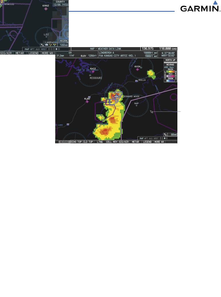
Map Panning on the Weather Data Link Page
Map panning (Figure 6-34) moves the map beyond its current limits without adjusting the map range. Press the Joystick to select the map panning feature.
Information
About Warning
Panning Arrow
Figure 6-34 Panning on the Weather Data Link Page
When map panning is enabled, a panning arrow flashes on the Weather Data Link Page. Panning over AIRMETs, County Warnings, TFRs (Temporary Flight Restrictions), Echo Tops, METARs, SIGMETs, and Cell Movement displays text information for the selection. This information is displayed in the same location as the map pointer information on the Navigation Map Page.
6-26 |
Garmin G1000 Pilot’s Guide for Cessna Nav III |
190-00498-02 Rev.A |
HAZARD AVOIDANCE
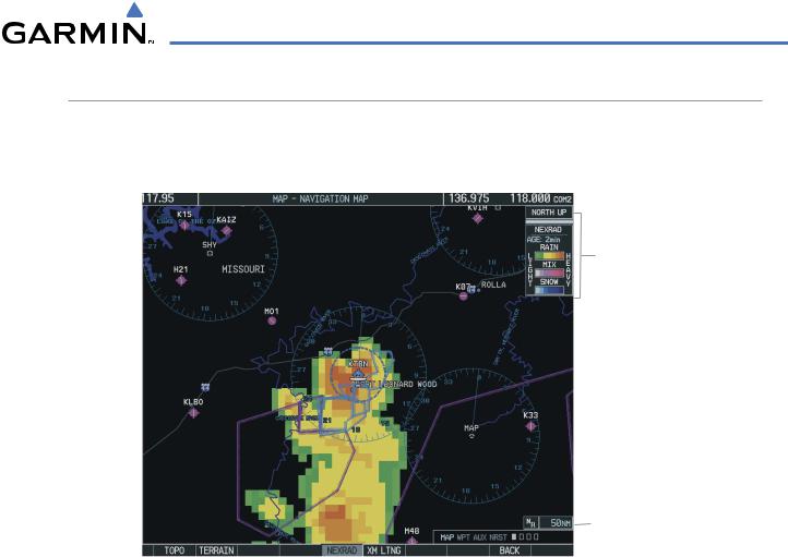
XM SATELLITE WEATHER ON THE NAVIGATION MAP
When appropriately configured, the Navigation Map displays NEXRAD, Cell Movement, TFRs, and XM Lightning data as shown in Figure 6-35. This improves situational awareness and makes it easier to relate storm activity to airports, NAVAIDS, obstacles, and other ground references.
Nexrad Products,
Storm Legend,
and Age
NEXRAD Icon
 50 nm Range
Figure 6-35 Navigation Map Page Displaying NEXRAD Weather
190-00498-02 Rev.A |
Garmin G1000 Pilot’s Guide for Cessna Nav III |
6-27 |
HAZARD AVOIDANCE
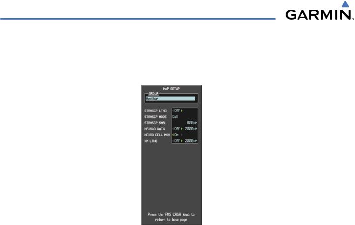
SETTING UP THE NAVIGATION MAP PAGE
Use the Map Setup Window (Figure 6-36) to customize the display of weather data on the Navigation Map Page. The Map Setup Window settings control the display of weather data on all G1000 pages except the Weather Data Link Page.
Figure 6-36 Map Setup Options
Setting up and customizing the Navigation Map Page:
1)On the Navigation Map Page, press the MENU Key.
2)While the ‘Map Setup’ selection is highlighted, press the ENT Key.
3)Turn the small FMS Knob to display the group selection window. Turn the small FMS Knob to select the ‘Weather Group’, and press the ENT Key.
4)Turn the large FMS Knob to highlight and move between the product selections.
5)When an item is highlighted, turn the small FMS Knob to select the desired option.
6)Press the ENT Key.
The following options are available:
•NEXRAD DATA – Turns the display of NEXRAD data and radar coverage on or off. Selects the display range.
•NEXRD CELL MOV – Turns the display of storm cell movement on or off. Cell Movement is shown only when NEXRAD is turned on.
•XM LTNG – Turns the display of XM Lightning on or off. Selects the display range.
6-28 |
Garmin G1000 Pilot’s Guide for Cessna Nav III |
190-00498-02 Rev.A |