- •Section 1 System Overview
- •1.1 System Description
- •1.2 Line Replaceable Units (LRU)
- •1.3 G1000 Controls
- •PFD/MFD Controls
- •Audio Panel Controls
- •1.4 Secure Digital (SD) Cards
- •1.5 System Power-up
- •1.6 System Operation
- •Normal Display Operation
- •Reversionary Display Operation
- •AHRS Operation
- •G1000 System Annunciations
- •Softkey Function
- •GPS Receiver Operation
- •1.7 Accessing G1000 Functionality
- •Menus
- •MFD Page Groups
- •MFD System Pages
- •Electronic Checklists (Optional)
- •1.8 Display Backlighting
- •Automatic Adjustment
- •Manual Adjustment
- •Section 2 flight Instruments
- •2.1 Flight Instruments
- •Airspeed Indicator
- •Attitude Indicator
- •Altimeter
- •Vertical Speed Indicator (VSI)
- •Vertical Deviation, Glideslope, & Glidepath Indicators
- •Horizontal Situation Indicator (HSI)
- •Course Deviation Indicator (CDI)
- •2.2 Supplemental Flight Data
- •Generic Timer
- •Outside Air Temperature
- •Wind Data
- •System Time
- •Vertical Navigation (VNV) Indications
- •2.3 PFD Annunciations and Alerting Functions
- •System Alerting
- •Traffic Annunciation
- •TAWS Annunciations
- •Low Altitude Annunciation
- •Altitude Alerting
- •Minimum Descent Altitude/Decision Height Alerting
- •Marker Beacon Annunciations
- •2.4 Abnormal Operations
- •Abnormal GPS Conditions
- •Unusual Attitudes
- •Section 3 Engine Indication System (EIS)
- •3.1 Engine Display
- •3.2 Lean Display
- •3.3 System Display
- •Section 4 audio panel and CNS
- •4.1 Overview
- •PFD/MFD Controls and Frequency Display
- •Audio Panel Controls
- •4.2 COM Operation
- •COM Transceiver Selection and Activation
- •COM Transceiver Manual Tuning
- •Quick-Tuning and Activating 121.500 MHz
- •Auto-tuning the COM Frequency
- •Frequency Spacing
- •Automatic Squelch
- •Volume
- •4.3 NAV Operation
- •NAV Radio Selection and Activation
- •NAV Receiver Manual Tuning
- •Auto-tuning the NAV Frequency
- •Marker Beacon Receiver
- •DME Tuning (Optional)
- •4.4 GTX 33 Mode S Transponder
- •Transponder Controls
- •Transponder Mode Selection
- •Entering a Transponder Code
- •IDENT Function
- •Flight ID Reporting
- •4.5 Additional Audio Panel Functions
- •Power-Up
- •Mono/Stereo Headsets
- •Speaker
- •Intercom
- •Clearance Recorder and Player
- •Entertainment Inputs
- •4.6 Audio Panel Preflight Procedure
- •4.7 Abnormal Operation
- •Stuck Microphone
- •COM Tuning Failure
- •Audio Panel Fail-Safe Operation
- •Reversionary Mode
- •Section 5 GPS Navigation
- •5.1 Introduction
- •5.2 Navigation Map (MFD)
- •Navigation Map Page
- •5.3 PFD Inset Map and Windows
- •Inset Map
- •PFD Windows
- •5.4 Direct-to-Navigation (MFD)
- •Selecting a Direct-to Waypoint
- •Clearing Vertical Constraints
- •Specifying a Course to a Waypoint
- •Canceling Direct-to Navigation
- •Direct-to Navigation Shortcuts
- •5.5 Direct-to-Navigation (PFD)
- •5.6 Airport Information (MFD)
- •Duplicate Waypoints
- •Additional Airport Runway Information
- •5.7 Intersection Information (MFD)
- •5.8 NDB Information (MFD)
- •5.9 VOR Information (MFD)
- •5.10 User Waypoint Information (MFD)
- •5.11 Nearest Airports (MFD)
- •5.12 Nearest Intersections (MFD)
- •5.13 Nearest NDB (MFD)
- •5.14 Nearest VOR (MFD)
- •5.15 Nearest User Waypoint (MFD)
- •5.16 Nearest Airspaces
- •5.17 Nearest Airports (PFD)
- •5.18 Flight Planning (MFD)
- •Airways/Jetways
- •Display of Airways on the Flight Plan Page
- •Vertical Navigation (VNV)
- •Navigating an Example Flight Plan
- •Parallel Track (PTK)
- •5.19 Flight Planning (PFD)
- •Operations
- •5.20 Procedures (MFD)
- •Leg Types Supported by the G1000
- •5.21 Procedures (PFD)
- •Operations
- •5.22 ABNORMAL OPERATION
- •Dead Reckoning
- •Section 6 Hazard Avoidance
- •6.1 XM Satellite Weather (Service Optional)
- •Activating XM Satellite Services
- •Using XM SATELLITE Weather Products
- •Weather Softkeys on the Weather Data Link Page
- •Setting Up the Weather Data Link Page
- •XM Satellite Weather on the Navigation Map
- •6.2 WX-500 Stormscope (Optional)
- •Setting Up Stormscope on the Navigation Map
- •Selecting the Stormscope Page
- •6.3 Terrain Proximity
- •Requirements
- •GPS Position and GPS-MSL Altitude
- •Displaying Terrain Proximity Data
- •Terrain Proximity Symbols
- •Terrain Proximity Page
- •Navigation Map Page
- •6.4 TAWS (Optional)
- •Requirements
- •TAWS Alerting
- •Using TAWS
- •TAWS Symbols
- •TAWS Alerts
- •6.5 Traffic
- •Traffic Information Service (TIS)
- •Honeywell KTA 870 TAS System (Optional)
- •ADS-B Traffic (Optional)
- •Section 7 Automatic Flight Control System
- •7.1 AFCS Controls
- •7.2 Flight Director Operation
- •Command Bars
- •Activating the Flight Director
- •7.3 Flight Director Modes
- •Pitch Modes
- •Roll Modes
- •7.4 Autopilot Operation
- •Engaging the Autopilot
- •Control Wheel Steering
- •Disengaging the Autopilot
- •7.5 Example Procedures
- •Departure
- •Intercepting a VOR Radial
- •Flying a Flight Plan/GPS Course
- •Descent
- •Approach
- •Go Around/Missed Approach
- •7.6 AFCS Annunciations and Alerts
- •AFCS Status Alerts
- •Overspeed Protection
- •Section 8 Additional Features
- •8.1 SafeTaxi
- •SafeTaxi Cycle Number and Revision
- •8.2 ChartView
- •ChartView Softkeys
- •Terminal Procedures Charts
- •Chart Options
- •Day/Night View
- •ChartView Cycle Number and Expiration Date
- •8.3 FliteCharts
- •FliteCharts Softkeys
- •Terminal Procedures Charts
- •Chart Options
- •Day/Night View
- •FliteCharts Cycle Number and Expiration Date
- •8.4 XM Radio Entertainment (Optional)
- •XM Satellite Radio Service
- •XM Service Activation
- •Using XM Radio
- •Automatic Audio Muting
- •8.5 Abnormal Operation
- •Annunciations and Alerts
- •Alert Level Definitions
- •NAV III Aircraft Alerts
- •CO Guardian Messages
- •G1000 System Annunciations
- •Other G1000 Aural Alerts
- •G1000 System Message Advisories
- •AFCS Alerts
- •TAWS ALERTS
- •TAWS System Status Annunciations
- •SD Card Use
- •Jeppesen Databases
- •Garmin Databases
- •Glossary
- •Frequently Asked Questions
- •General TIS Information
- •Introduction
- •TIS vs. TAS/TCAS
- •TIS Limitations
- •Map Symbols
- •Index
FLIGHT INSTRUMENTS
2.2 SUPPLEMENTAL FLIGHT DATA
NOTE: Pressing the DFLTS Softkey (a second-level PFD softkey) turns off metric Altimeter display, the Inset Map, and wind data.
In addition to the flight insturments, various supplemental information is also displayed on the PFD, including a generic timer, the Outside Air Temperature (OAT), wind data, the system time, and Vertical Navigation (VNV) indications.
GENERIC TIMER
The Timer/References Window contains a generic timer, which can be set to count up or down from a specified time (HH:MM:SS). When the countdown on the timer reaches zero the digits begin to count up. If the timer is reset before reaching zero on a countdown, the digits are reset to the initial value. If the timer is counting up when reset, the digits are zeroed.
Figure 2-31 Timer/References Window
Setting the generic timer:
1)Press the TMR/REF Softkey.
2)Turn the large FMS Knob to select the time field (hh/mm/ss).
3)Use the FMS Knob to enter the desired time and press the ENT Key.
4)With the UP/DN field highlighted, turn the small FMS Knob to select the timer counting direction.
5)Press the ENT Key.
6)With ‘START?’ highlighted, press the ENT Key to start the timer. The field changes to ‘STOP?’.
7)To stop the timer, press the ENT Key with ‘STOP?’ highlighted. The field changes to ‘RESET?’.
8)To reset the timer, press the ENT Key with ‘RESET?’ highlighted. The field changes back to ‘START?’ and the digits are reset.
9)To remove the window, press the CLR Key or the TMR/REF Softkey.
190-00498-02 Rev.A |
Garmin G1000 Pilot’s Guide for Cessna Nav III |
2-21 |
FLIGHT INSTRUMENTS
OUTSIDE AIR TEMPERATURE
The Outside Air Temperature (OAT) is displayed in degrees Celsius (°C) by default in the lower left of the PFD under normal display conditions, or below the true airspeed in reversionary mode.
Normal Display |
Reversionary Mode |
Figure 2-30 Outside Air Temperature
WIND DATA
Wind direction and speed (relative to the aircraft) can be displayed in a window to the upper left of the HSI. When the window is selected for display, but wind information is invalid or unavailable, the window shows “NO WIND DATA”. Wind data can be displayed in three different ways:
•Longitudinal and lateral components (Option 1)
•Total wind direction and speed (Option 2)
•Total direction with head and crosswind speed components (Option 3)
Option 1 |
Option 2 |
Option 3 |
No Data |
Figure 2-32 Wind Data
Displaying wind data:
1)Press the PFD Softkey.
2)Press the WIND Softkey to display wind data below the Selected Heading.
3)Press one of the OPTN softkeys to change how wind data is displayed.
4)To remove the window, press the OFF Softkey.
2-22 |
Garmin G1000 Pilot’s Guide for Cessna Nav III |
190-00498-02 Rev.A |
FLIGHT INSTRUMENTS
SYSTEM TIME
The system time is displayed in the lower right corner of the PFD. Three display formats are available, local 12-hr, local 24-hr, and Coordinated Universal Time (UTC). Time and date are obtained from the GPS satellites and cannot be changed, although a time offset may be entered (±HH:MM) for local times.
Figure 2-33 System Time
Configuring the system time:
1)Select the AUX - System Setup Page using the FMS Knob.
2)Press the FMS Knob to activate the cursor. ‘Time Format’ is highlighted.
3)Turn the small FMS Knob to select the desired format.
4)Press the ENT Key to confirm selection. ‘Time Offset’ is highlighted (for local time formats).
5)Enter the desired time offset (±HH:MM) for local time formats.
6)Press the ENT Key to confirm selection.
Figure 2-34 System Setup Page,
Date/Time Settings
190-00498-02 Rev.A |
Garmin G1000 Pilot’s Guide for Cessna Nav III |
2-23 |
FLIGHT INSTRUMENTS
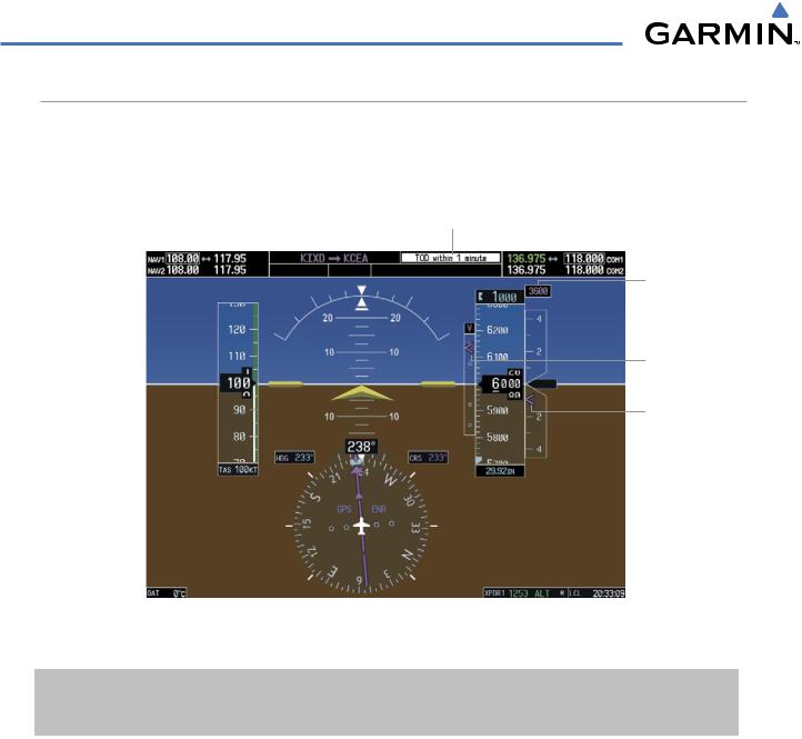
VERTICAL NAVIGATION (VNV) INDICATIONS
When a VNV flight plan has been activated, VNV indications (VNV Target Altitude, RSVI, VDI) appear on the PFD in conjunction with the “TOD within 1 minute” message (Figure 2-35) and “Vertical track” voice alert. See the GPS Navigation and AFCS sections for details on VNV features. VNV indications are removed from the PFD according to the criteria listed in Table 2-2.
Top of Descent Message
VNV Target
Altitude
Vertical Deviation
Indicator
Required Vertical
Speed Bug
GPS is Selected |
|
Enroute Phase |
||
|
|
|
|
|
Navigation Source |
|
of Flight |
Figure 2-35 Vertical Navigation Indications (PFD)
|
VNV Indication Removed |
|
||
Criteria |
Required Vertical |
Vertical |
|
VNV Target |
|
Speed (RSVI) |
Deviation (VDI) |
|
Altitude* |
Aircraft > 1 min before the next TOD and not on a descent leg |
X |
X |
|
X |
Aircraft > 1 min before the next TOD due to flight plan change |
X |
X |
|
X |
VNV cancelled (CNCL VNV Softkey pressed on MFD) |
X |
X |
|
X |
Distance to active waypoint cannot be computed due to |
X |
X |
|
X |
unsupported flight plan leg type (see GPS Navigation Section) |
|
|||
|
|
|
|
|
Aircraft > 250 feet below active VNV Target Altitude |
X |
X |
|
X |
Current crosstrack or track angle error has exceeded limit |
X |
X |
|
X |
Active altitude-constrained waypoint can not be reached within |
X |
X |
|
|
maximum allowed flight path angle and vertical speed |
|
|
||
|
|
|
|
|
Last altitude-constrained waypoint in active flight plan reached |
X |
X |
|
X |
(30 sec before) |
|
|||
|
|
|
|
*If the flight director has been engaged to fly a VNV flight plan, the VNV Target Altitude being held remains displayed while on level flight plan legs.
Table 2-2 VNV Indication Removal Criteria
2-24 |
Garmin G1000 Pilot’s Guide for Cessna Nav III |
190-00498-02 Rev.A |