

- •Section 1 System Overview
- •1.1 System Description
- •1.2 Line Replaceable Units (LRU)
- •1.3 G1000 Controls
- •PFD/MFD Controls
- •Audio Panel Controls
- •1.4 Secure Digital (SD) Cards
- •1.5 System Power-up
- •1.6 System Operation
- •Normal Display Operation
- •Reversionary Display Operation
- •AHRS Operation
- •G1000 System Annunciations
- •Softkey Function
- •GPS Receiver Operation
- •1.7 Accessing G1000 Functionality
- •Menus
- •MFD Page Groups
- •MFD System Pages
- •Electronic Checklists (Optional)
- •1.8 Display Backlighting
- •Automatic Adjustment
- •Manual Adjustment
- •Section 2 flight Instruments
- •2.1 Flight Instruments
- •Airspeed Indicator
- •Attitude Indicator
- •Altimeter
- •Vertical Speed Indicator (VSI)
- •Vertical Deviation, Glideslope, & Glidepath Indicators
- •Horizontal Situation Indicator (HSI)
- •Course Deviation Indicator (CDI)
- •2.2 Supplemental Flight Data
- •Generic Timer
- •Outside Air Temperature
- •Wind Data
- •System Time
- •Vertical Navigation (VNV) Indications
- •2.3 PFD Annunciations and Alerting Functions
- •System Alerting
- •Traffic Annunciation
- •TAWS Annunciations
- •Low Altitude Annunciation
- •Altitude Alerting
- •Minimum Descent Altitude/Decision Height Alerting
- •Marker Beacon Annunciations
- •2.4 Abnormal Operations
- •Abnormal GPS Conditions
- •Unusual Attitudes
- •Section 3 Engine Indication System (EIS)
- •3.1 Engine Display
- •3.2 Lean Display
- •3.3 System Display
- •Section 4 audio panel and CNS
- •4.1 Overview
- •PFD/MFD Controls and Frequency Display
- •Audio Panel Controls
- •4.2 COM Operation
- •COM Transceiver Selection and Activation
- •COM Transceiver Manual Tuning
- •Quick-Tuning and Activating 121.500 MHz
- •Auto-tuning the COM Frequency
- •Frequency Spacing
- •Automatic Squelch
- •Volume
- •4.3 NAV Operation
- •NAV Radio Selection and Activation
- •NAV Receiver Manual Tuning
- •Auto-tuning the NAV Frequency
- •Marker Beacon Receiver
- •DME Tuning (Optional)
- •4.4 GTX 33 Mode S Transponder
- •Transponder Controls
- •Transponder Mode Selection
- •Entering a Transponder Code
- •IDENT Function
- •Flight ID Reporting
- •4.5 Additional Audio Panel Functions
- •Power-Up
- •Mono/Stereo Headsets
- •Speaker
- •Intercom
- •Clearance Recorder and Player
- •Entertainment Inputs
- •4.6 Audio Panel Preflight Procedure
- •4.7 Abnormal Operation
- •Stuck Microphone
- •COM Tuning Failure
- •Audio Panel Fail-Safe Operation
- •Reversionary Mode
- •Section 5 GPS Navigation
- •5.1 Introduction
- •5.2 Navigation Map (MFD)
- •Navigation Map Page
- •5.3 PFD Inset Map and Windows
- •Inset Map
- •PFD Windows
- •5.4 Direct-to-Navigation (MFD)
- •Selecting a Direct-to Waypoint
- •Clearing Vertical Constraints
- •Specifying a Course to a Waypoint
- •Canceling Direct-to Navigation
- •Direct-to Navigation Shortcuts
- •5.5 Direct-to-Navigation (PFD)
- •5.6 Airport Information (MFD)
- •Duplicate Waypoints
- •Additional Airport Runway Information
- •5.7 Intersection Information (MFD)
- •5.8 NDB Information (MFD)
- •5.9 VOR Information (MFD)
- •5.10 User Waypoint Information (MFD)
- •5.11 Nearest Airports (MFD)
- •5.12 Nearest Intersections (MFD)
- •5.13 Nearest NDB (MFD)
- •5.14 Nearest VOR (MFD)
- •5.15 Nearest User Waypoint (MFD)
- •5.16 Nearest Airspaces
- •5.17 Nearest Airports (PFD)
- •5.18 Flight Planning (MFD)
- •Airways/Jetways
- •Display of Airways on the Flight Plan Page
- •Vertical Navigation (VNV)
- •Navigating an Example Flight Plan
- •Parallel Track (PTK)
- •5.19 Flight Planning (PFD)
- •Operations
- •5.20 Procedures (MFD)
- •Leg Types Supported by the G1000
- •5.21 Procedures (PFD)
- •Operations
- •5.22 ABNORMAL OPERATION
- •Dead Reckoning
- •Section 6 Hazard Avoidance
- •6.1 XM Satellite Weather (Service Optional)
- •Activating XM Satellite Services
- •Using XM SATELLITE Weather Products
- •Weather Softkeys on the Weather Data Link Page
- •Setting Up the Weather Data Link Page
- •XM Satellite Weather on the Navigation Map
- •6.2 WX-500 Stormscope (Optional)
- •Setting Up Stormscope on the Navigation Map
- •Selecting the Stormscope Page
- •6.3 Terrain Proximity
- •Requirements
- •GPS Position and GPS-MSL Altitude
- •Displaying Terrain Proximity Data
- •Terrain Proximity Symbols
- •Terrain Proximity Page
- •Navigation Map Page
- •6.4 TAWS (Optional)
- •Requirements
- •TAWS Alerting
- •Using TAWS
- •TAWS Symbols
- •TAWS Alerts
- •6.5 Traffic
- •Traffic Information Service (TIS)
- •Honeywell KTA 870 TAS System (Optional)
- •ADS-B Traffic (Optional)
- •Section 7 Automatic Flight Control System
- •7.1 AFCS Controls
- •7.2 Flight Director Operation
- •Command Bars
- •Activating the Flight Director
- •7.3 Flight Director Modes
- •Pitch Modes
- •Roll Modes
- •7.4 Autopilot Operation
- •Engaging the Autopilot
- •Control Wheel Steering
- •Disengaging the Autopilot
- •7.5 Example Procedures
- •Departure
- •Intercepting a VOR Radial
- •Flying a Flight Plan/GPS Course
- •Descent
- •Approach
- •Go Around/Missed Approach
- •7.6 AFCS Annunciations and Alerts
- •AFCS Status Alerts
- •Overspeed Protection
- •Section 8 Additional Features
- •8.1 SafeTaxi
- •SafeTaxi Cycle Number and Revision
- •8.2 ChartView
- •ChartView Softkeys
- •Terminal Procedures Charts
- •Chart Options
- •Day/Night View
- •ChartView Cycle Number and Expiration Date
- •8.3 FliteCharts
- •FliteCharts Softkeys
- •Terminal Procedures Charts
- •Chart Options
- •Day/Night View
- •FliteCharts Cycle Number and Expiration Date
- •8.4 XM Radio Entertainment (Optional)
- •XM Satellite Radio Service
- •XM Service Activation
- •Using XM Radio
- •Automatic Audio Muting
- •8.5 Abnormal Operation
- •Annunciations and Alerts
- •Alert Level Definitions
- •NAV III Aircraft Alerts
- •CO Guardian Messages
- •G1000 System Annunciations
- •Other G1000 Aural Alerts
- •G1000 System Message Advisories
- •AFCS Alerts
- •TAWS ALERTS
- •TAWS System Status Annunciations
- •SD Card Use
- •Jeppesen Databases
- •Garmin Databases
- •Glossary
- •Frequently Asked Questions
- •General TIS Information
- •Introduction
- •TIS vs. TAS/TCAS
- •TIS Limitations
- •Map Symbols
- •Index
HAZARD AVOIDANCE
TAWS SYMBOLS
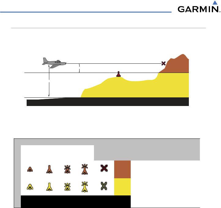
The symbols and colors in Figure 6-50 and Table 6-8 are used to represent obstacles and potential impact points on the TAWS Page. TAWS uses yellow (caution) and red (warning) to depict terrain information relative to aircraft altitude.
Potential Impact Point
Projected Flight Path
100 ft Threshold
Unlighted Obstacle
1000 ft
Figure 6-50 Terrain Altitude/Color Correlation for TAWS
Each color is associated with an alert severity level. Terrain graphics and visual annunciations also use these color assignments.
Obstacle Symbol
Unlighted Obstacle |
Lighted Obstacle |
Potential |
Terrain |
|
|
||
|
|
|
|
Impact |
Terrain/Obstacle Location |
Alert Level |
|
< 1000’ |
> 1000’ |
< 1000’ |
> 1000’ |
||||
AGL |
AGL |
AGL |
AGL |
Points |
Color |
|
|
|
|
|
|
||||
|
|
|
|
|
|
|
|
|
|
|
|
|
|
Terrain/Obstacle above or |
|
|
|
|
|
|
Red |
within 100’ below current |
WARNING |
|
|
|
|
|
|
aircraft altitude |
|
|
|
|
|
|
|
Terrain/Obstacle between |
|
|
|
|
|
|
Yellow |
100’ and 1000’ below |
CAUTION |
|
|
|
|
|
|
current aircraft altitude |
|
|
|
|
|
|
Black |
Terrain more than 1000’ |
NO DANGER |
|
|
|
|
|
|
below the aircraft altitude |
|
Table 6-8 TAWS Terrain/Obstacle Colors and Symbology
Note that if an obstacle and the projected flight path of the aircraft intersect, the display automatically zooms in to the closest potential point of impact on the TAWS Page.
6-46 |
Garmin G1000 Pilot’s Guide for Cessna Nav III |
190-00498-02 Rev.A |
HAZARD AVOIDANCE
TAWS ALERTS
Alerts are issued when flight conditions meet parameters that are set within TAWS software algorithms. TAWS alerts typically employ either a CAUTION or a WARNING alert severity level, or both. When an alert is issued, visual annunciations are displayed. Aural alerts are simultaneously issued.
Annunciations appear in the lower right corner of the MFD display (Figure 6-51).
Figure 6-51 Alert Annunciation on the MFD
Annunciations also appear on the PFD (Figure 6-52).
Alert Annunciation
Figure 6-52 Alert Annunciation on the PFD
190-00498-02 Rev.A |
Garmin G1000 Pilot’s Guide for Cessna Nav III |
6-47 |

HAZARD AVOIDANCE
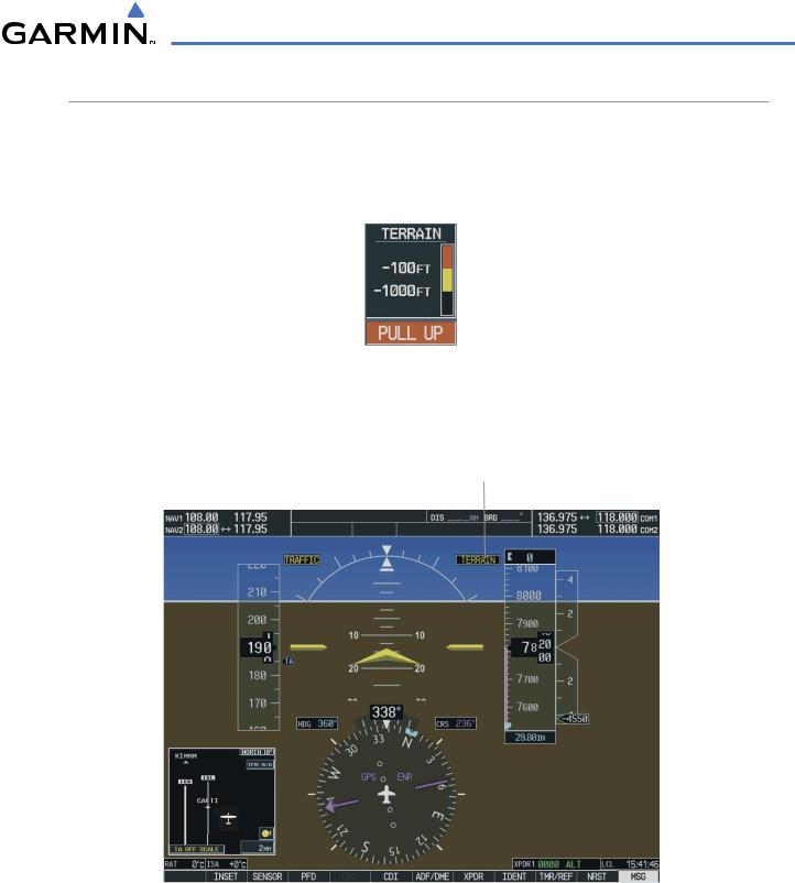
The aural alert voice gender is configurable on the AUX - System Setup Page to be either male or female. Annunciations appear on the PFD and MFD. Pop-up alerts appear only on the MFD.
Figure 6-53 Alert Pop-up
Pop-up terrain alerts (Figure 6-53) can also appear on the MFD during an alert, but only when the TAWS Page is not displayed. When an alert displays, the pilot can:
•Press the CLR Key. This acknowledges the pop-up alert and returns to the currently viewed page.
•Press the ENT Key. This acknowledges the pop-up alert and accesses the TAWS Page.
6-48 |
Garmin G1000 Pilot’s Guide for Cessna Nav III |
190-00498-02 Rev.A |
HAZARD AVOIDANCE
Table 6-9 shows the possible TAWS alert types with corresponding annunciations and aural messages.
 NOTE: Alerts with multiple messages are configurable at installation and are installation-dependent.
|
PFD/MFD |
|
|
|
Alert Type |
TAWS Page |
MFD Map Page |
Aural Message |
|
Annuncia- |
Pop-Up Alert |
|||
|
|
|||
|
tion |
|
|
|
Excessive Descent RateWarning (EDR) |
|
|
“Pull Up” |
|
|
|
|
|
|
Reduced RequiredTerrain Clearance |
|
* |
“Terrain,Terrain; Pull Up, Pull Up”* |
|
Warning (RTC) |
|
|||
|
or |
or |
||
|
|
|||
|
|
|
“TerrainAhead, Pull Up;TerrainAhead, Pull Up” |
|
ImminentTerrain ImpactWarning (ITI) |
|
* |
TerrainAhead, Pull Up;TerrainAhead, Pull Up’* |
|
|
|
|||
|
|
or |
or |
|
|
|
|
“Terrain,Terrain; Pull Up, Pull Up” |
|
Reduced Required Obstacle Clearance |
|
* |
“Obstacle, Obstacle; Pull Up, Pull Up”* |
|
Warning (ROC) |
|
|||
|
or |
or |
||
|
|
|||
|
|
|
“ObstacleAhead, Pull Up; ObstacleAhead, Pull Up” |
|
Imminent Obstacle ImpactWarning (IOI) |
|
* |
“ObstacleAhead, Pull Up; ObstacleAhead, Pull Up”* |
|
|
|
|||
|
|
or |
or |
|
|
|
|
“Obstacle, Obstacle; Pull Up, Pull Up” |
|
Reduced RequiredTerrain Clearance |
|
* |
“Caution,Terrain; Caution,Terrain”* |
|
Caution (RTC) |
|
|||
|
or |
or |
||
|
|
|||
|
|
|
“TerrainAhead;TerrainAhead” |
|
ImminentTerrain Impact Caution (ITI) |
|
* |
“TerrainAhead;TerrainAhead”* |
|
|
|
|||
|
|
or |
or |
|
|
|
|
“Caution,Terrain; Caution,Terrain” |
|
Reduced Required Obstacle Clearance |
|
* |
“Caution, Obstacle; Caution, Obstacle”* |
|
Caution (ROC) |
|
|||
|
or |
or |
||
|
|
|||
|
|
|
“ObstacleAhead; ObstacleAhead” |
|
Imminent Obstacle Impact Caution (IOI) |
|
* |
“ObstacleAhead; ObstacleAhead”* |
|
|
|
|||
|
|
or |
or |
|
|
|
|
“Caution, Obstacle; Caution, Obstacle” |
|
Premature DescentAlert Caution (PDA) |
|
|
“Too Low,Terrain” |
|
|
|
|
|
|
Altitude Callout “500” |
None |
None |
“Five-Hundred” |
|
Excessive Descent Rate Caution (EDR) |
|
|
“Sink Rate” |
|
|
|
|
|
|
Negative Climb Rate Caution (NCR) |
|
* |
“Don’t Sink”* |
|
|
|
|||
|
|
or |
or |
|
|
|
|
“Too Low,Terrain” |
* Indicates the default configuration
Table 6-9 TAWS Alerts Summary
190-00498-02 Rev.A |
Garmin G1000 Pilot’s Guide for Cessna Nav III |
6-49 |
HAZARD AVOIDANCE
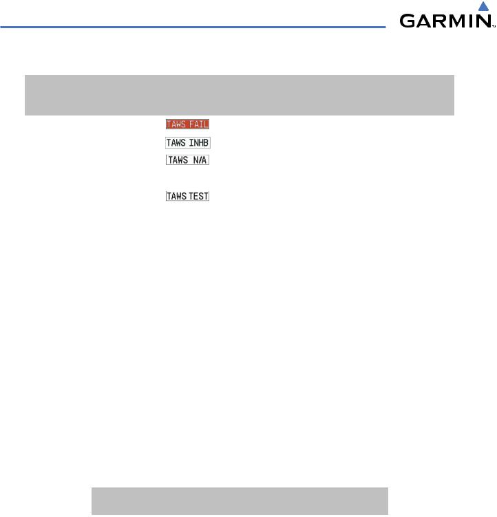
Table 6-10 shows system status annunciations that may also be issued:
|
PFD/MFD TAWS |
MFD |
|
|
Alert Type |
Page |
Aural Message |
||
Pop-Up Alert |
||||
|
Annunciation |
|
||
|
|
|
||
TAWS SystemTest Fail |
|
None |
“TAWS System Failure” |
|
|
|
|
|
|
TAWSAlerting is disabled |
|
None |
None |
|
|
|
|
|
|
No GPS position or excessively degraded |
|
None |
“TAWS NotAvailable” |
|
GPS signal |
|
|
“TAWSAvailable” is generated when sufficient |
|
|
|
|
GPS signal is re-established. |
|
SystemTest in progress |
|
None |
None |
|
|
|
|
|
|
SystemTest pass |
None |
None |
“TAWS SystemTest OK” |
|
|
|
|
|
Table 6-10 Additional System Annunciations
FORWARD LOOKING TERRAIN AVOIDANCE
The Forward Looking Terrain Avoidance (FLTA) alert is used by TAWS and is composed of:
•REDUCED REQUIRED TERRAIN CLEARANCE AND REDUCED REQUIRED OBSTACLE CLEARANCE
Reduced Required Terrain Clearance (RTC) and Reduced Required Obstacle Clearance (ROC) alerts are issued when the aircraft flight path is above terrain, yet is projected to come within the minimum clearance values in Table 6-11. When an RTC alert is issued, a potential impact point is displayed on the TAWS Page.
•IMMINENT TERRAIN IMPACT AND IMMINENT OBSTACLE IMPACT
Imminent Terrain Impact (ITI) and Imminent Obstacle Impact (IOI) alerts are issued when the aircraft is below the elevation of a terrain or obstacle cell in the aircraft’s projected path. ITI and IOI alerts are accompanied by a potential impact point displayed on the TAWS Page. The alert is annunciated when the projected vertical flight path is calculated to come within minimum clearance altitudes in Table 6-11.
Phase of Flight |
Minimum Clearance |
Minimum Clearance |
|
Altitude Level Flight (ft) |
Altitude Descending (ft) |
Enroute |
700 |
500 |
Terminal |
350 |
300 |
Approach |
150 |
100 |
Departure |
100 |
100 |
Table 6-11 Minimum Terrain and Obstacle Clearance Values for FLTA Alerts
During the final approach phase of flight, FLTA alerts are automatically inhibited when the aircraft is below 200 feet AGL while within 0.5 nm of the approach runway or below 125 feet AGL while within 1.0 nm of the runway threshold.
6-50 |
Garmin G1000 Pilot’s Guide for Cessna Nav III |
190-00498-02 Rev.A |
HAZARD AVOIDANCE
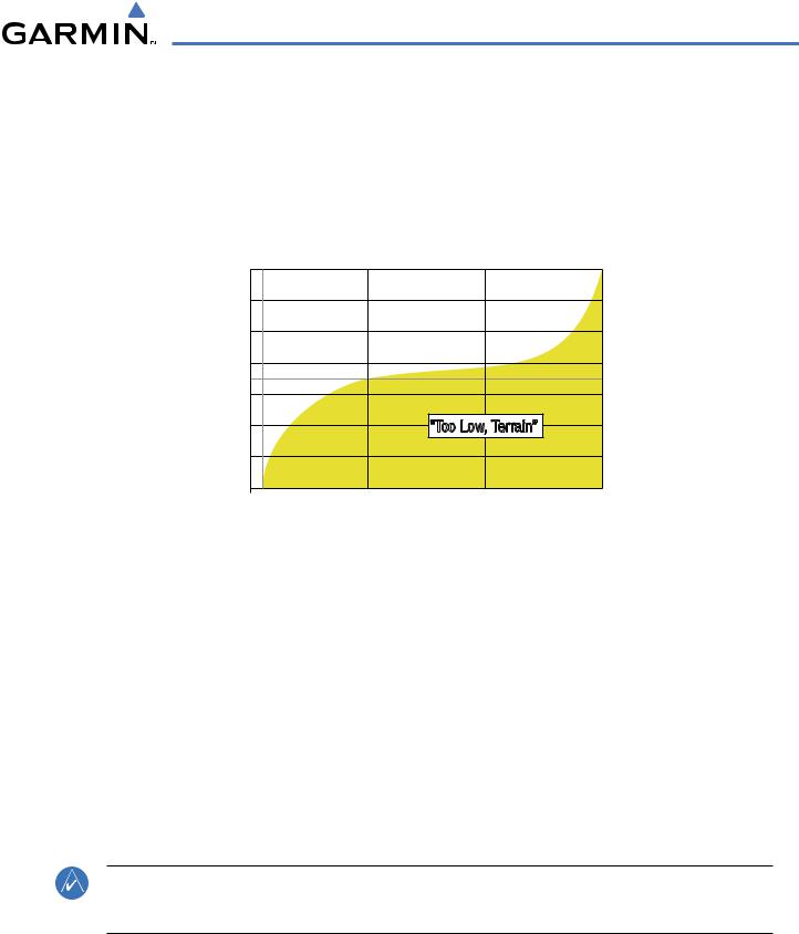
PREMATURE DESCENT ALERTING
A Premature Descent Alert (PDA) is issued when the system detects that the aircraft is significantly below the normal approach path to a runway (Figure 6-54).
PDA alerting begins when the aircraft is within 15 nm of the destination airport and ends when the aircraft is either 0.5 nm from the runway threshold OR is at an altitude of 125 feet AGL while within 1.0 nm of the threshold. During the final descent, algorithms will set a threshold for alerting based on speed, distance, and other parameters.
Height Above Terrain (Feet)
700
600
500
400
300
200 |
|
|
|
|
|
|
|
“Too Low, Terrain” |
|
|
|
||||
100 |
|
|
|
|
|
|
|
|
|
|
|
|
|
|
|
Runway |
1 |
2 |
3 |
4 |
5 |
6 |
7 |
8 |
9 |
10 |
11 |
12 |
13 |
14 |
15 |
Threshold |
|
|
|
Distance From Destination Airport (nm) |
|
|
|
|
|||||||
|
|
|
|
|
|
|
|
||||||||
Figure 6-54 PDA Alerting Threshold
TAWS INHIBIT
TAWS also has an inhibit mode that deactivates the PDA/FLTA aural and visual alerts. Pilots should use discretion when inhibiting TAWS and always remember to enable the system when appropriate. Only the PDA and FLTA alerts are disabled in the inhibit mode. For more information, see the section on TAWS alerts.
Inhibiting and enabling TAWS:
1)Select the TAWS Page.
2)Press the MENU Key. ‘Inhibit TAWS’ or ‘Enable TAWS’ is highlighted.
3)PresstheENTKey. TheTAWSsystemisinhibitedorenabled,dependingonthepreviousstatus. Theannunciation is displayed in the terrain annunciator field whenever terrain is inhibited.
NOTE: If TAWS alerts are inhibited when the Final Approach Fix is the active waypoint in a GPS WAAS approach, a LOWALT annunciation may appear on the PFD next to the altimeter if the current aircraft altitude is at least 164 feet below the prescribed altitude at the FinalApproach Fix.
190-00498-02 Rev.A |
Garmin G1000 Pilot’s Guide for Cessna Nav III |
6-51 |
HAZARD AVOIDANCE
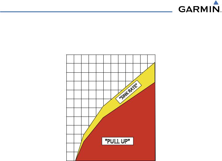
EXCESSIVE DESCENT RATE ALERT
The purpose of the Excessive Descent Rate (EDR) alert is to provide suitable notification when the aircraft is determined to be closing (descending) upon terrain at an excessive speed. Figure 6-55 shows the parameters for the alert as defined by TSO-C151b.
|
6000 |
|
|
|
|
|
|
|
5500 |
|
|
|
|
|
|
|
5000 |
|
|
|
|
|
|
(Feet) |
4500 |
|
|
|
|
|
|
4000 |
|
|
|
TE" |
|
|
|
|
|
|
RA |
|
|
||
Terrain |
|
|
|
"SINK |
|
|
|
3500 |
|
|
|
|
|
||
|
|
|
|
|
|
||
3000 |
|
|
|
|
|
|
|
Above |
|
|
|
|
|
|
|
2500 |
|
|
|
|
|
|
|
|
|
|
|
|
|
|
|
Height |
2000 |
|
|
|
|
|
|
1500 |
|
|
|
|
|
|
|
|
|
|
|
|
|
|
|
|
1000 |
|
"PULL UP" |
|
|
||
|
500 |
|
|
|
|
|
|
|
0 |
4000 |
6000 |
8000 |
|
10000 |
12000 |
|
2000 |
|
|||||
Descent Rate (FPM)
Figure 6-55 Excessive Descent Rate Alert Criteria
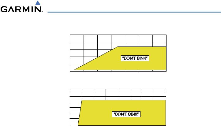
NEGATIVE CLIMB RATE AFTER TAKEOFF ALERT (NCR)
The purpose of the Negative Climb Rate (NCR) After Takeoff alert (also referred to as “Altitude Loss After Takeoff”) is to provide suitable alerts to the pilot when the system determines that the aircraft is losing altitude (closing upon terrain) after takeoff. The aural message “Don’t Sink” is given for NCR alerts, accompanied by an annunciation and a pop-up terrain alert on the display. NCR alerting is only active when departing from an airport and when the following conditions are met:
•The height above the terrain is less than 700 feet.
•The distance from the departure airport is 2 nm or less.
•The heading change from the heading at the time of departure is less than 110 degrees.
6-52 |
Garmin G1000 Pilot’s Guide for Cessna Nav III |
190-00498-02 Rev.A |
HAZARD AVOIDANCE
Figure 6-56 shows the NCR alerting parameters as defined by TSO-C151b.
(Feet) |
1000 |
|
|
|
|
|
|
|
|
800 |
|
|
|
|
|
|
|
||
Terrain |
|
|
|
|
|
|
|
||
600 |
|
|
|
|
|
|
|
||
|
|
|
|
|
|
|
|
||
Above |
400 |
|
|
|
“DON’T SINK” |
|
|
||
|
|
|
|
|
|
||||
200 |
|
|
|
|
|
|
|
||
Height |
|
|
|
|
|
|
|
||
0 |
20 |
40 |
60 |
80 |
100 |
120 |
140 |
||
|
|||||||||
Altitude Loss (Feet)
(Feet) |
1000 |
|
|
|
|
|
|
|
|
|
900 |
|
|
|
|
|
|
|
|
||
800 |
|
|
|
|
|
|
|
|
||
Terrain |
|
|
|
|
|
|
|
|
||
700 |
|
|
|
|
|
|
|
|
||
600 |
|
|
|
|
|
|
|
|
||
500 |
|
|
|
|
|
|
|
|
||
Above |
|
|
|
|
|
|
|
|
||
400 |
|
|
|
“DON’T SINK” |
|
|
|
|||
300 |
|
|
|
|
|
|
||||
200 |
|
|
|
|
|
|
|
|
||
Height |
|
|
|
|
|
|
|
|
||
100 |
|
|
|
|
|
|
|
|
||
0 |
500 |
1000 |
1500 |
2000 |
2500 |
3000 |
3500 |
4000 |
||
|
||||||||||
Sink Rate (Feet Per Minute)
Figure 6-56 Negative Climb Rate (NCR) Alert Criteria
FIVE-HUNDRED AURAL ALERT
The purpose of the aural alert message “Five-hundred” is to provide an advisory alert to the pilot that the aircraft is 500 feet above terrain. When the aircraft descends within 500 feet of terrain, the aural message “five-hundred” is generated. There are no display annunciations or pop-up alerts that accompany the aural message.
TAWS NOT AVAILABLE ALERT
TAWS requires a 3-D GPS navigation solution along with specific vertical accuracy minimums. Should the navigation solution become degraded or if the aircraft is out of the database coverage area, the annunciation ‘TAWS N/A’ is generated in the annunciation window and on the TAWS Page. The aural message “TAWS Not Available” is generated. When the GPS signal is re-established and the aircraft is within the database coverage
area, the aural message “TAWS Available” is generated.
TAWS FAILURE ALERT
TAWS continually monitors several system-critical items such as database validity, hardware status, and GPS status. If the terrain/obstacle database is not available, the aural message “TAWS System Failure” is generated along with a ‘TAWS FAIL’ annunciation.
190-00498-02 Rev.A |
Garmin G1000 Pilot’s Guide for Cessna Nav III |
6-53 |