

- •Section 1 System Overview
- •1.1 System Description
- •1.2 Line Replaceable Units (LRU)
- •1.3 G1000 Controls
- •PFD/MFD Controls
- •Audio Panel Controls
- •1.4 Secure Digital (SD) Cards
- •1.5 System Power-up
- •1.6 System Operation
- •Normal Display Operation
- •Reversionary Display Operation
- •AHRS Operation
- •G1000 System Annunciations
- •Softkey Function
- •GPS Receiver Operation
- •1.7 Accessing G1000 Functionality
- •Menus
- •MFD Page Groups
- •MFD System Pages
- •Electronic Checklists (Optional)
- •1.8 Display Backlighting
- •Automatic Adjustment
- •Manual Adjustment
- •Section 2 flight Instruments
- •2.1 Flight Instruments
- •Airspeed Indicator
- •Attitude Indicator
- •Altimeter
- •Vertical Speed Indicator (VSI)
- •Vertical Deviation, Glideslope, & Glidepath Indicators
- •Horizontal Situation Indicator (HSI)
- •Course Deviation Indicator (CDI)
- •2.2 Supplemental Flight Data
- •Generic Timer
- •Outside Air Temperature
- •Wind Data
- •System Time
- •Vertical Navigation (VNV) Indications
- •2.3 PFD Annunciations and Alerting Functions
- •System Alerting
- •Traffic Annunciation
- •TAWS Annunciations
- •Low Altitude Annunciation
- •Altitude Alerting
- •Minimum Descent Altitude/Decision Height Alerting
- •Marker Beacon Annunciations
- •2.4 Abnormal Operations
- •Abnormal GPS Conditions
- •Unusual Attitudes
- •Section 3 Engine Indication System (EIS)
- •3.1 Engine Display
- •3.2 Lean Display
- •3.3 System Display
- •Section 4 audio panel and CNS
- •4.1 Overview
- •PFD/MFD Controls and Frequency Display
- •Audio Panel Controls
- •4.2 COM Operation
- •COM Transceiver Selection and Activation
- •COM Transceiver Manual Tuning
- •Quick-Tuning and Activating 121.500 MHz
- •Auto-tuning the COM Frequency
- •Frequency Spacing
- •Automatic Squelch
- •Volume
- •4.3 NAV Operation
- •NAV Radio Selection and Activation
- •NAV Receiver Manual Tuning
- •Auto-tuning the NAV Frequency
- •Marker Beacon Receiver
- •DME Tuning (Optional)
- •4.4 GTX 33 Mode S Transponder
- •Transponder Controls
- •Transponder Mode Selection
- •Entering a Transponder Code
- •IDENT Function
- •Flight ID Reporting
- •4.5 Additional Audio Panel Functions
- •Power-Up
- •Mono/Stereo Headsets
- •Speaker
- •Intercom
- •Clearance Recorder and Player
- •Entertainment Inputs
- •4.6 Audio Panel Preflight Procedure
- •4.7 Abnormal Operation
- •Stuck Microphone
- •COM Tuning Failure
- •Audio Panel Fail-Safe Operation
- •Reversionary Mode
- •Section 5 GPS Navigation
- •5.1 Introduction
- •5.2 Navigation Map (MFD)
- •Navigation Map Page
- •5.3 PFD Inset Map and Windows
- •Inset Map
- •PFD Windows
- •5.4 Direct-to-Navigation (MFD)
- •Selecting a Direct-to Waypoint
- •Clearing Vertical Constraints
- •Specifying a Course to a Waypoint
- •Canceling Direct-to Navigation
- •Direct-to Navigation Shortcuts
- •5.5 Direct-to-Navigation (PFD)
- •5.6 Airport Information (MFD)
- •Duplicate Waypoints
- •Additional Airport Runway Information
- •5.7 Intersection Information (MFD)
- •5.8 NDB Information (MFD)
- •5.9 VOR Information (MFD)
- •5.10 User Waypoint Information (MFD)
- •5.11 Nearest Airports (MFD)
- •5.12 Nearest Intersections (MFD)
- •5.13 Nearest NDB (MFD)
- •5.14 Nearest VOR (MFD)
- •5.15 Nearest User Waypoint (MFD)
- •5.16 Nearest Airspaces
- •5.17 Nearest Airports (PFD)
- •5.18 Flight Planning (MFD)
- •Airways/Jetways
- •Display of Airways on the Flight Plan Page
- •Vertical Navigation (VNV)
- •Navigating an Example Flight Plan
- •Parallel Track (PTK)
- •5.19 Flight Planning (PFD)
- •Operations
- •5.20 Procedures (MFD)
- •Leg Types Supported by the G1000
- •5.21 Procedures (PFD)
- •Operations
- •5.22 ABNORMAL OPERATION
- •Dead Reckoning
- •Section 6 Hazard Avoidance
- •6.1 XM Satellite Weather (Service Optional)
- •Activating XM Satellite Services
- •Using XM SATELLITE Weather Products
- •Weather Softkeys on the Weather Data Link Page
- •Setting Up the Weather Data Link Page
- •XM Satellite Weather on the Navigation Map
- •6.2 WX-500 Stormscope (Optional)
- •Setting Up Stormscope on the Navigation Map
- •Selecting the Stormscope Page
- •6.3 Terrain Proximity
- •Requirements
- •GPS Position and GPS-MSL Altitude
- •Displaying Terrain Proximity Data
- •Terrain Proximity Symbols
- •Terrain Proximity Page
- •Navigation Map Page
- •6.4 TAWS (Optional)
- •Requirements
- •TAWS Alerting
- •Using TAWS
- •TAWS Symbols
- •TAWS Alerts
- •6.5 Traffic
- •Traffic Information Service (TIS)
- •Honeywell KTA 870 TAS System (Optional)
- •ADS-B Traffic (Optional)
- •Section 7 Automatic Flight Control System
- •7.1 AFCS Controls
- •7.2 Flight Director Operation
- •Command Bars
- •Activating the Flight Director
- •7.3 Flight Director Modes
- •Pitch Modes
- •Roll Modes
- •7.4 Autopilot Operation
- •Engaging the Autopilot
- •Control Wheel Steering
- •Disengaging the Autopilot
- •7.5 Example Procedures
- •Departure
- •Intercepting a VOR Radial
- •Flying a Flight Plan/GPS Course
- •Descent
- •Approach
- •Go Around/Missed Approach
- •7.6 AFCS Annunciations and Alerts
- •AFCS Status Alerts
- •Overspeed Protection
- •Section 8 Additional Features
- •8.1 SafeTaxi
- •SafeTaxi Cycle Number and Revision
- •8.2 ChartView
- •ChartView Softkeys
- •Terminal Procedures Charts
- •Chart Options
- •Day/Night View
- •ChartView Cycle Number and Expiration Date
- •8.3 FliteCharts
- •FliteCharts Softkeys
- •Terminal Procedures Charts
- •Chart Options
- •Day/Night View
- •FliteCharts Cycle Number and Expiration Date
- •8.4 XM Radio Entertainment (Optional)
- •XM Satellite Radio Service
- •XM Service Activation
- •Using XM Radio
- •Automatic Audio Muting
- •8.5 Abnormal Operation
- •Annunciations and Alerts
- •Alert Level Definitions
- •NAV III Aircraft Alerts
- •CO Guardian Messages
- •G1000 System Annunciations
- •Other G1000 Aural Alerts
- •G1000 System Message Advisories
- •AFCS Alerts
- •TAWS ALERTS
- •TAWS System Status Annunciations
- •SD Card Use
- •Jeppesen Databases
- •Garmin Databases
- •Glossary
- •Frequently Asked Questions
- •General TIS Information
- •Introduction
- •TIS vs. TAS/TCAS
- •TIS Limitations
- •Map Symbols
- •Index
HAZARD AVOIDANCE
6.4 TAWS (OPTIONAL)
TAWS (Terrain Awareness and Warning System) is an optional feature to increase situational awareness and aid inreducingcontrolledflightintoterrain(CFIT). TAWSsatisfiesTSO-C151bClassBrequirementsforcertification. Class B TAWS is required for all Part 91 aircraft operations with six or more passenger seats and for Part 135 turbine aircraft operations with six to nine passenger seats (FAR Parts 91.223, 135.154).
TAWSprovidesvisualandauralannunciationswhenterrainandobstaclesarewithinthegivenaltitudethreshold from the aircraft.
REQUIREMENTS
TAWS requires the following to operate properly:
•The system must have a valid 3-D GPS position solution.
•The system must have a valid terrain/obstacle/airport terrain database.
LIMITATIONS
 NOTE: The data contained in the TAWS databases comes from government agencies. Garmin accurately processes and cross-validates the data but cannot guarantee the accuracy and completeness of the data.
TAWS displays terrain and obstructions relative to the altitude of the aircraft. The displayed alerts and warnings are advisory in nature only. Individual obstructions may be shown if available in the database. However, all obstructions may not be available in the database and data may be inaccurate. Never use this information for navigation or to maneuver to avoid obstacles.
Terrain information is based on terrain elevation information in a database that may contain inaccuracies. Terrain information should be used as an aid to situational awareness. Never use it for navigation or to maneuver to avoid terrain.
TAWSusesterrainandobstacleinformationsuppliedbygovernmentsources. Thedataundergoesverification by Garmin to confirm accuracy of the content, per TSO-C151b. However, the displayed information should never be understood as being all-inclusive.
TAWS ALERTING
TAWS uses information provided from the GPS receiver to provide a horizontal position and altitude. GPS altitude is derived from satellite measurements. GPS altitude is converted to a mean sea level (MSL)-based altitude (GPS-MSL altitude) and is used to determine TAWS alerts. GPS-MSL altitude accuracy is affected by factors such as satellite geometry, but it is not subject to variations in pressure and temperature that normally affect pressure altitude devices. GPS-MSL altitude does not require local altimeter settings to determine MSL altitude. Therefore, GPS altitude provides a highly accurate and reliable MSL altitude source to calculate terrain and obstacle alerts.
TAWS utilizes terrain and obstacle databases that are referenced to mean sea level (MSL). Using the GPS position and GPS-MSL altitude, TAWS displays a 2-D picture of the surrounding terrain and obstacles relative to the position and altitude of the aircraft. Furthermore, the GPS position and GPS-MSL altitude are used to calculate and “predict” the aircraft’s flight path in relation to the surrounding terrain and obstacles. In this
190-00498-02 Rev.A |
Garmin G1000 Pilot’s Guide for Cessna Nav III |
6-41 |

HAZARD AVOIDANCE
manner, TAWS can provide advanced alerts of predicted dangerous terrain conditions. Detailed alert modes are described later in this section.
BARO-CORRECTED ALTITUDE VERSUS GPS-MSL ALTITUDE
Baro-corrected altitude (or indicated altitude) is derived by adjusting the altimeter setting for local atmospheric conditions. The most accurate baro-corrected altitude can be achieved by frequently updating thealtimetersettingtothenearestreportingstationalongtheflightpath. However,becauseactualatmosphere conditions seldom match the standard conditions defined by the International Standard Atmosphere (ISA) model (where pressure, temperature, and lapse rates have fixed values), it is common for the baro-corrected altitude (as read from the altimeter) to differ from the GPS-MSL altitude. This variation results in the aircraft’s true altitude differing from the baro-corrected altitude.
USING TAWS
During G1000 power-up, the terrain/obstacle database versions are displayed along with a disclaimer to the pilot. At the same time, TAWS self-test begins. One of the following aural messages is generated:
•“TAWS System Test OK”
•“TAWS System Failure”
TAWS information can be displayed on the following pages:
• TAWS Page |
• AUX - Trip Planning Page |
• Navigation Map |
• Flight Plan Pages |
• PFD Inset Map |
|
TAWS can also be displayed on the PFD Inset Map by pressing the INSET Softkey, then the TERRAIN Softkey. TAWS display may also be deselected from the Inset Map without affecting the display on the MFD maps.
TodisplayTAWSdataonanypageotherthantheTAWSPage,presstheMAPSoftkey,thenpresstheTERRAIN Softkey. Terrain and obstacles with heights greater than 200 feet above ground level (AGL) are displayed in three color levels (Table 6-8). The G1000 adjusts colors automatically as the aircraft altitude changes.
6-42 |
Garmin G1000 Pilot’s Guide for Cessna Nav III |
190-00498-02 Rev.A |
HAZARD AVOIDANCE
TAWS PAGE
The TAWS Page is in the MAP group of pages and displays the following:
•GPS-derived MSL altitude in increments of 20 feet or 10 meters, depending on unit configuration
•Aircraft ground track
•Terrain Range - Indicates the terrain elevation in colors relative to the aircraft altitude
•Range marking rings (360º View: 1 nm, 1 and 2 nm, 2.5 and 5 nm, 5 and 10 nm, 12.5 and 25 nm, 25 and 50 nm, 50 and 100 nm, 100 and 200 nm) (Arc View: 1 nm, 2 nm, 5 nm, 10 nm, 25 nm, 25 and 50 nm, 25 and 100 nm, 25 and 200 nm)
•Heading Box (North Up, Track Up, DTK Up, HDG Up) - Heading on the TAWS Page displays ‘HDG Up’ map data, unless there is no valid heading
•Obstacles
•Potential Impact Points
Displaying the TAWS Page:
1)Select the NAV Page Group.
2)Select the last rectangular page icon.
3)Turn the Joystick clockwise to display a larger area or counter-clockwise to display a smaller area.
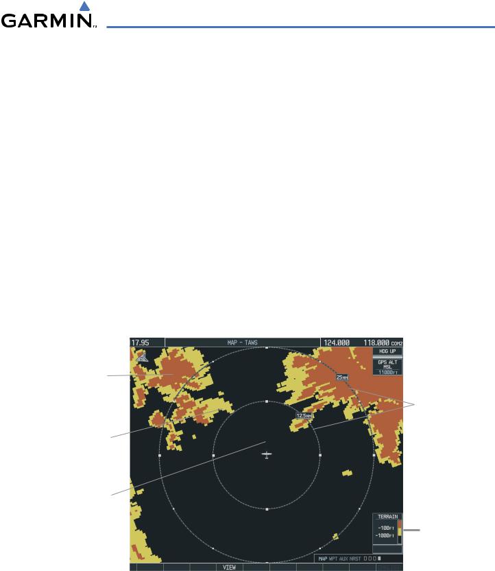
Red Terrain (Warning
- Terrain Above or
Within 100’ Below
the Aircraft Altitude)
Map Range
Yellow Terrain
(Caution - Terrain
Between 100’ and
1000’ Below the
Aircraft Altitude)
Black Terrain (No
Danger - Terrain More
than 1000’ Below the
Aircraft Altitude)
Terrain Legend
Figure 6-47 360˚ View on the TAWS Page
The TAWS Page has two view settings:
•360˚ View—Displays surrounding terrain on all sides of aircraft (Figure 6-47).
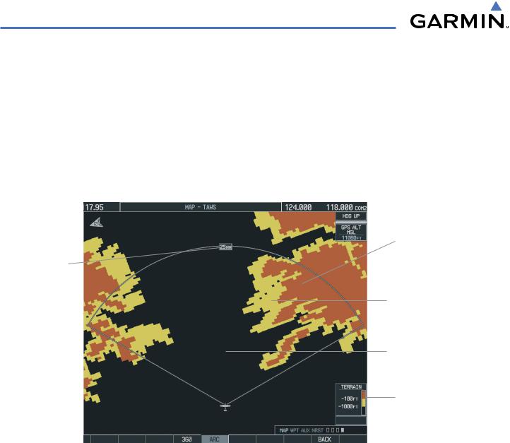
•ARC (120˚) View—Displays terrain ahead of and 60˚ to either side of the aircraft flight path (Figure 6-48).
190-00498-02 Rev.A |
Garmin G1000 Pilot’s Guide for Cessna Nav III |
6-43 |
HAZARD AVOIDANCE
Changing the viewing mode between 360° and Arc:
1)Select the TAWS Page.
2)Press the VIEW Softkey.
3)Press the 360 or ARC Softkey to select the desired view.
OR:
1)Press the MENU Key. The page menu is displayed with either ‘View Arc’ or ‘View 360º’. Press the ENT Key to change the view.
2)Turn the Joystick clockwise to display a larger area or counter-clockwise to display a smaller area.
Red Terrain (Warning
- Terrain Above or
Within 100’ Below
the Aircraft Altitude)
Map Range
Yellow Terrain
(Caution - Terrain
Between 100’ and
1000’ Below the
Aircraft Altitude)
Black Terrain (No
Danger - Terrain More
than 1000’ Below the
Aircraft Altitude)
Terrain Legend
Figure 6-48 TAWS Page (ARC View)
6-44 |
Garmin G1000 Pilot’s Guide for Cessna Nav III |
190-00498-02 Rev.A |
HAZARD AVOIDANCE
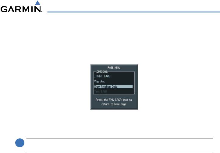
Other aviation information such as airports, VORs, and other NAVAIDS can be displayed or hidden on the TAWS Page (Figure 6-49).
Showing or hiding aviation information:
1)Press the MENU Key.
2)Select ‘Show (or Hide) Aviation Data’ and press the ENT Key.
Figure 6-49 TAWS Page Menu
TAWS MANUAL TEST
 NOTE: TAWS SystemTesting is disabled when ground speed exceeds 30 knots in order not to impedeTAWS alerting.
TAWS provides a manual test which verifies the proper operation of the aural and visual annunciations of the system prior to a flight.
Manually testing the TAWS System:
1)Select the TAWS Page and press the MENU Key.
2)Select the ‘Test TAWS’ option.
3)Press the ENT Key to confirm the selection.
One of the following aural messages is generated:
•“TAWS System Test, OK”
•“TAWS System Failure”
TAWS TEST is annunciated in yellow on the TAWS Page and in white on the PFD.
190-00498-02 Rev.A |
Garmin G1000 Pilot’s Guide for Cessna Nav III |
6-45 |