

- •Section 1 System Overview
- •1.1 System Description
- •1.2 Line Replaceable Units (LRU)
- •1.3 G1000 Controls
- •PFD/MFD Controls
- •Audio Panel Controls
- •1.4 Secure Digital (SD) Cards
- •1.5 System Power-up
- •1.6 System Operation
- •Normal Display Operation
- •Reversionary Display Operation
- •AHRS Operation
- •G1000 System Annunciations
- •Softkey Function
- •GPS Receiver Operation
- •1.7 Accessing G1000 Functionality
- •Menus
- •MFD Page Groups
- •MFD System Pages
- •Electronic Checklists (Optional)
- •1.8 Display Backlighting
- •Automatic Adjustment
- •Manual Adjustment
- •Section 2 flight Instruments
- •2.1 Flight Instruments
- •Airspeed Indicator
- •Attitude Indicator
- •Altimeter
- •Vertical Speed Indicator (VSI)
- •Vertical Deviation, Glideslope, & Glidepath Indicators
- •Horizontal Situation Indicator (HSI)
- •Course Deviation Indicator (CDI)
- •2.2 Supplemental Flight Data
- •Generic Timer
- •Outside Air Temperature
- •Wind Data
- •System Time
- •Vertical Navigation (VNV) Indications
- •2.3 PFD Annunciations and Alerting Functions
- •System Alerting
- •Traffic Annunciation
- •TAWS Annunciations
- •Low Altitude Annunciation
- •Altitude Alerting
- •Minimum Descent Altitude/Decision Height Alerting
- •Marker Beacon Annunciations
- •2.4 Abnormal Operations
- •Abnormal GPS Conditions
- •Unusual Attitudes
- •Section 3 Engine Indication System (EIS)
- •3.1 Engine Display
- •3.2 Lean Display
- •3.3 System Display
- •Section 4 audio panel and CNS
- •4.1 Overview
- •PFD/MFD Controls and Frequency Display
- •Audio Panel Controls
- •4.2 COM Operation
- •COM Transceiver Selection and Activation
- •COM Transceiver Manual Tuning
- •Quick-Tuning and Activating 121.500 MHz
- •Auto-tuning the COM Frequency
- •Frequency Spacing
- •Automatic Squelch
- •Volume
- •4.3 NAV Operation
- •NAV Radio Selection and Activation
- •NAV Receiver Manual Tuning
- •Auto-tuning the NAV Frequency
- •Marker Beacon Receiver
- •DME Tuning (Optional)
- •4.4 GTX 33 Mode S Transponder
- •Transponder Controls
- •Transponder Mode Selection
- •Entering a Transponder Code
- •IDENT Function
- •Flight ID Reporting
- •4.5 Additional Audio Panel Functions
- •Power-Up
- •Mono/Stereo Headsets
- •Speaker
- •Intercom
- •Clearance Recorder and Player
- •Entertainment Inputs
- •4.6 Audio Panel Preflight Procedure
- •4.7 Abnormal Operation
- •Stuck Microphone
- •COM Tuning Failure
- •Audio Panel Fail-Safe Operation
- •Reversionary Mode
- •Section 5 GPS Navigation
- •5.1 Introduction
- •5.2 Navigation Map (MFD)
- •Navigation Map Page
- •5.3 PFD Inset Map and Windows
- •Inset Map
- •PFD Windows
- •5.4 Direct-to-Navigation (MFD)
- •Selecting a Direct-to Waypoint
- •Clearing Vertical Constraints
- •Specifying a Course to a Waypoint
- •Canceling Direct-to Navigation
- •Direct-to Navigation Shortcuts
- •5.5 Direct-to-Navigation (PFD)
- •5.6 Airport Information (MFD)
- •Duplicate Waypoints
- •Additional Airport Runway Information
- •5.7 Intersection Information (MFD)
- •5.8 NDB Information (MFD)
- •5.9 VOR Information (MFD)
- •5.10 User Waypoint Information (MFD)
- •5.11 Nearest Airports (MFD)
- •5.12 Nearest Intersections (MFD)
- •5.13 Nearest NDB (MFD)
- •5.14 Nearest VOR (MFD)
- •5.15 Nearest User Waypoint (MFD)
- •5.16 Nearest Airspaces
- •5.17 Nearest Airports (PFD)
- •5.18 Flight Planning (MFD)
- •Airways/Jetways
- •Display of Airways on the Flight Plan Page
- •Vertical Navigation (VNV)
- •Navigating an Example Flight Plan
- •Parallel Track (PTK)
- •5.19 Flight Planning (PFD)
- •Operations
- •5.20 Procedures (MFD)
- •Leg Types Supported by the G1000
- •5.21 Procedures (PFD)
- •Operations
- •5.22 ABNORMAL OPERATION
- •Dead Reckoning
- •Section 6 Hazard Avoidance
- •6.1 XM Satellite Weather (Service Optional)
- •Activating XM Satellite Services
- •Using XM SATELLITE Weather Products
- •Weather Softkeys on the Weather Data Link Page
- •Setting Up the Weather Data Link Page
- •XM Satellite Weather on the Navigation Map
- •6.2 WX-500 Stormscope (Optional)
- •Setting Up Stormscope on the Navigation Map
- •Selecting the Stormscope Page
- •6.3 Terrain Proximity
- •Requirements
- •GPS Position and GPS-MSL Altitude
- •Displaying Terrain Proximity Data
- •Terrain Proximity Symbols
- •Terrain Proximity Page
- •Navigation Map Page
- •6.4 TAWS (Optional)
- •Requirements
- •TAWS Alerting
- •Using TAWS
- •TAWS Symbols
- •TAWS Alerts
- •6.5 Traffic
- •Traffic Information Service (TIS)
- •Honeywell KTA 870 TAS System (Optional)
- •ADS-B Traffic (Optional)
- •Section 7 Automatic Flight Control System
- •7.1 AFCS Controls
- •7.2 Flight Director Operation
- •Command Bars
- •Activating the Flight Director
- •7.3 Flight Director Modes
- •Pitch Modes
- •Roll Modes
- •7.4 Autopilot Operation
- •Engaging the Autopilot
- •Control Wheel Steering
- •Disengaging the Autopilot
- •7.5 Example Procedures
- •Departure
- •Intercepting a VOR Radial
- •Flying a Flight Plan/GPS Course
- •Descent
- •Approach
- •Go Around/Missed Approach
- •7.6 AFCS Annunciations and Alerts
- •AFCS Status Alerts
- •Overspeed Protection
- •Section 8 Additional Features
- •8.1 SafeTaxi
- •SafeTaxi Cycle Number and Revision
- •8.2 ChartView
- •ChartView Softkeys
- •Terminal Procedures Charts
- •Chart Options
- •Day/Night View
- •ChartView Cycle Number and Expiration Date
- •8.3 FliteCharts
- •FliteCharts Softkeys
- •Terminal Procedures Charts
- •Chart Options
- •Day/Night View
- •FliteCharts Cycle Number and Expiration Date
- •8.4 XM Radio Entertainment (Optional)
- •XM Satellite Radio Service
- •XM Service Activation
- •Using XM Radio
- •Automatic Audio Muting
- •8.5 Abnormal Operation
- •Annunciations and Alerts
- •Alert Level Definitions
- •NAV III Aircraft Alerts
- •CO Guardian Messages
- •G1000 System Annunciations
- •Other G1000 Aural Alerts
- •G1000 System Message Advisories
- •AFCS Alerts
- •TAWS ALERTS
- •TAWS System Status Annunciations
- •SD Card Use
- •Jeppesen Databases
- •Garmin Databases
- •Glossary
- •Frequently Asked Questions
- •General TIS Information
- •Introduction
- •TIS vs. TAS/TCAS
- •TIS Limitations
- •Map Symbols
- •Index

GPS NAVIGATION
5.20 PROCEDURES (MFD)
LEG TYPES SUPPORTED BY THE G1000
There are currently 23 different database leg types. All 23 published procedures and leg types are supported by the G1000 and available to the pilot for flight planning.
• AF - DME arc to a fix |
• RF – Constant radius turn to fix |
• CF – Course to a fix |
• TF – Track between two fixes |
• DF – Direct to a fix |
• CA – Course to an altitude |
• FA – Course from fix to an altitude |
• CD – Course to a DME distance |
• FC – Course from fix to distance |
• CI – Course to an intercept |
• FD – Course from fix to DME distance |
• CR – Course to a radial |
• FM – Course from fix to manual termination |
• VA – Heading vector to an altitude |
• HA – Hold terminating at altitude |
• VD – Heading vector to DME distance |
• HF – Hold terminating at a fix |
• VI – Heading vector to an intercept |
• HM – Hold with manual termination |
• VM – Heading vector to manual termination |
• IF – Initial fix |
• VR – Heading vector to a radial |
• PI – Procedure turn to course intercept |
|
 NOTE: The G1000 supports vertical navigation for all lateral leg types except for CA, CI, FA, FM, HA, HM, PI, VA,VD,VI,VR, and VM.
5-134 |
Garmin G1000 Pilot’s Guide for Cessna Nav III |
190-00498-02 Rev.A |
GPS NAVIGATION
DEPARTURES, ARRIVALS, AND APPROACHES
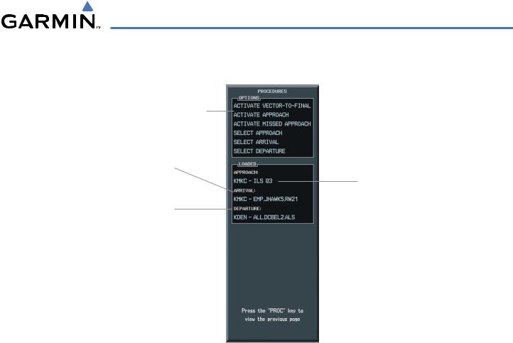
Options
Arrival Loaded in Active Flight
Plan
Approach Procedure Loaded in
Active Flight Plan
Departure Procedure Loaded in
Active Flight Plan
Figure 5-136 Procedures Window
DEPARTURE OPERATIONS
Loading and activating a departure procedure:
1)Press the PROC Key. The Procedures Window is displayed (Figure 5-136).
2)Highlight ‘SELECT DEPARTURE’.
3)Press the ENT Key. The DEPARTURE window is displayed on the ‘PROC – DEPARTURE LOADING Page.
4)Select a departure.
5)Press the ENT Key. The RUNWAY window may be displayed.
6)Select a runway.
7)Press the ENT Key. The TRANSITION window may be displayed.
8)Select a transition.
9)Press the ENT Key.
10)With ‘LOAD’ highlighted, press the ENT Key. The departure procedure is displayed as part of the overall flight plan and is placed in front of the enroute flight plan.
OR:
1)With the Departure Information Page displayed (Figure 5-137), press the FMS Knob to activate the cursor.
2)Enter an identifier, facility name or city location field.
190-00498-02 Rev.A |
Garmin G1000 Pilot’s Guide for Cessna Nav III |
5-135 |
GPS NAVIGATION
3)Press the ENT Key until the DEPARTURE window is displayed.
4)Select a departure.
5)Press the ENT Key. The RUNWAY window may be displayed.
6)Select a runway.
7)Press the ENT Key. The TRANSITION window may be displayed.
8)Select a transition.
9)Press the ENT Key. The departure is now ready to load.
10)Press the FMS Knob to remove the cursor.
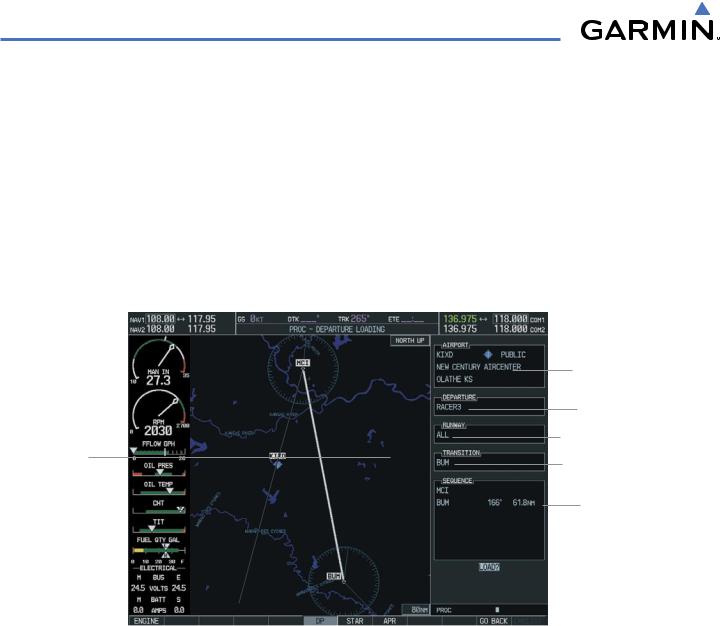
Map Showing
Selected
Departure
Figure 5-137 Departure Information Page
Airport Information
Available Departures
Available Runways
Available Transitions
List of Legs
in Departure
Sequence
Activating a departure leg:
1)Press the FPL key.
2)Press the FMS Knob to activate the cursor.
3)Turn the large FMS Knob to highlight the desired waypoint within the departure.
4)Press the ACT LEG Softkey. A confirmation window showing the selected leg will be displayed.
5)With ‘ACTIVATE’ highlighted, press the ENT key.
5-136 |
Garmin G1000 Pilot’s Guide for Cessna Nav III |
190-00498-02 Rev.A |

GPS NAVIGATION
Figure 5-138 Activate Leg Option
Viewing a Departure Airport:
1)Select the Departure Information Page.
2)Press the MENU Key.
3)Highlight ‘View Departure Airport’.
4)Press the ENT Key. The Departure Airport Page is displayed.
OR:
1)Select the Approach Information Page.
2)Press the MENU Key.
3)Highlight ‘View Departure Airport’.
4)Press the ENT Key. The Departure Information Page is displayed.
OR:
1)Select the Arrival Information Page.
2)Press the MENU Key.
3)Highlight ‘View Departure Airport’.
4)Press the ENT Key. The Departure Information Page is displayed.
5)Enter an identifier, facility, or city name for the departure airport.
Removing a departure:
1)From the Active Flight Plan Window, press the MENU Key.
2)Select the ‘Remove Departure’ option.
3)Press the ENT Key. A confirmation window is displayed listing the procedure.
4)With ‘OK’ highlighted, press the ENT Key. To cancel the removal request, highlight ‘CANCEL’ and press the ENT Key.
190-00498-02 Rev.A |
Garmin G1000 Pilot’s Guide for Cessna Nav III |
5-137 |
GPS NAVIGATION
 NOTE: Remove the current Arrival Procedure before loading a new one.
ARRIVAL OPERATIONS
Loading an arrival procedure:
1)Select the ‘WPT’ page group.
2)Select the first rectangular page icon.
3)Press the STAR Softkey.
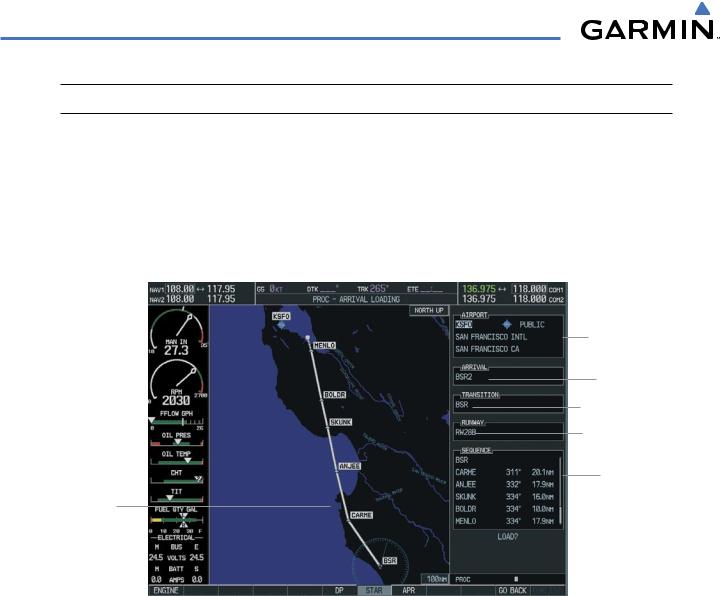
Map Showing
Selected Arrival
Figure 5-139 Arrival Loading Page
Arrival Airport Information
Available Departures
Available Transitions
Available Runways
List of Legs
in Departure
Sequence
4)Select an arrival.
5)Press the ENT Key. The TRANSITION window is displayed.
6)Select a transition.
7)Press the ENT Key. The RUNWAY window may be displayed. If so, select a runway.
8)Press the ENT Key.
9)With ‘LOAD’ highlighted, press the ENT Key. The arrival procedure is displayed as part of the overall flight plan and is placed at the end of the enroute flight plan.
OR:
1)Press the PROC Softkey.
2)Highlight ‘SELECT ARRIVAL’.
3)Press the ENT Key. The ARRIVAL window is displayed on the ‘PROC – ARRIVAL LOADING’ Page.
4)Select an arrival.
5-138 |
Garmin G1000 Pilot’s Guide for Cessna Nav III |
190-00498-02 Rev.A |

GPS NAVIGATION
5)Press the ENT Key. The TRANSITION window is displayed.
6)Select a transition.
7)Press the ENT Key. The RUNWAY window may be displayed. If so, select a runway.
8)Press the ENT Key.
9)With ‘LOAD’ highlighted, press the ENT Key. The arrival procedure is displayed as part of the overall flight plan and is placed at the end of the enroute flight plan.
OR:
1)Select the Arrival Information Page.
2)Press the MENU Key.
3)Highlight ‘Load Arrival’.
4)Press the ENT Key. The Active Flight Plan Page is displayed. The arrival procedure is displayed as part of the overall flight plan and is placed at the end of the enroute flight plan.
Removing an arrival:
1)From the Active Flight Plan Window, press the MENU Key.
2)Select the ‘Remove Approach’,‘Remove Arrival’ or ‘Remove Departure’ option.
3)Press the ENT Key. A confirmation window is displayed listing the procedure.
4)With‘OK’ highlighted,press the ENT Key. To cancel the removal request,highlight‘CANCEL’ and press the ENT Key.
190-00498-02 Rev.A |
Garmin G1000 Pilot’s Guide for Cessna Nav III |
5-139 |
GPS NAVIGATION
APPROACH OPERATIONS
Not all approaches in the database are approved for GPS use. When selecting an approach, a “GPS” designation to the right of the procedure name indicates the procedure can be flown using the GPS receiver. Some procedures will not have this designation, meaning the GPS receiver can be used for supplemental navigation guidance only. If the GPS receiver cannot be used for primary guidance, the appropriate navigation receiver must be used for the selected approach (e.g., VOR or ILS). The final course segment of ILS approaches, for example, must be flown by tuning the NAV receiver to the proper frequency and selecting that NAV receiver on the CDI.
TheG1000WAASGPSallowsforflyingLNAV,LNAV/VNAV,andLPVapproachesaccordingtothepublished chart. The active appoach type will be annunciated on the HSI as shown in the following table:
HSI |
DESCRIPTION |
ANNUNCIATION |
|
|
|
LNAV |
GPS approach using published |
|
LNAV minima. |
LNAV+V |
GPS approach using published |
|
LNAV minima. Advisory vertical |
|
guidance is provided. |
L/VNAV |
GPS approach using published |
|
LNAV/VNAV minima. |
LPV |
GPS approach using published |
|
LPV minima. |
Map Showing
Selected
Approach
WAAS Approach
Channels
Available Approaches
List of Legs
in Departure
Sequence
Figure 5-140 Approach Loading Page
5-140 |
Garmin G1000 Pilot’s Guide for Cessna Nav III |
190-00498-02 Rev.A |
GPS NAVIGATION
Load and/or activate an approach procedure:
1)Press the PROC Key.
2)Highlight ‘SELECT APPROACH’.
3)Press the ENT Key. A list of available approaches for the destination airport is displayed.
4)Turn either FMS Knob to highlight the desired approach. The WAAS channel and ID for the selected approach procedure are displayed in the ‘APPROACH CHANNEL’ field (Figure 5-141).
5)Press the ENT Key. A list of available transitions for the selected approach procedure is now displayed.
6)Turn either FMS Knob to selected the desired transition. The “Vectors” option assumes vectors will be received to the final course segment of the approach and will provide navigation guidance relative to the final approach course.
7)Press the ENT Key. ACTIVATE?’ is now displayed. Selecting‘LOAD?’ will enter the selected approach procedure into the active flight plan,but will not be currently active. Selecting‘ACTIVATE?’ will enter the selected approach procedure into the active flight plan and make it immediately active.
8)Turn the large FMS Knob to select either ‘LOAD?’ or ‘ACTIVATE?’.
9)Press the ENT Key.
Figure 5-141 Not Approved for GPS Message
OR:
1)Select the Nearest Airports Page.
2)Select the desired nearest airport.
3)Press the APR Softkey located at the bottom of the display. The LD APR (load approach) Softkey becomes available.
4)Select the desired approach.
5)Press the LD APR Softkey. The Approach Loading Page is displayed with the transitions field highlighted.
6)Select the desired transition.
7)Press the ENT Key. The ‘LOAD?’ field is highlighted.
8)Press the ENT Key to load the approach. If navigating a flight plan previous to loading this approach,the G1000 will continue navigating the flight plan until the approach is activated.
9)Highlight the ‘ACTIVATE’ field.
10)Press the ENT Key to activate the approach and begin navigating to the IAP.
190-00498-02 Rev.A |
Garmin G1000 Pilot’s Guide for Cessna Nav III |
5-141 |

GPS NAVIGATION
11)IftheapproachisnotapprovedforGPS,a‘NOTAPPROVEDFORGPS’messageisdisplayedwith‘YES’highlighted. Press the ENT Key to acknowledge the message (or select ‘NO’).
12)Press the ENT Key to return to the Approach Loading Page.
OR:
1)From any page, press the PROC Key. The Procedures Options Menu is displayed.
2)Highlight ‘SELECT APPROACH’.
3)Press the ENT Key. The APPROACH window is displayed on the ‘PROC – APPROACH LOADING’ Page.
4)Select an approach.
5)Press the ENT Key. The TRANSITION window is displayed.
6)Select a transition (the ‘VECTORS’ option assumes vectors will be received to the final course segment of the approach and will provide navigation guidance relative to the final approach course.)
7)Press the ENT Key.
8)Highlight ‘LOAD?’ or ‘ACTIVATE?’. ‘LOAD’ adds the approach to the flight plan without immediately using the approach for navigation guidance. This allows for the original flight plan to continue navigating until cleared for the approach, but keeps the approach available for quick activation when needed. ‘ACTIVATE’ adds the approach to the flight plan and begins navigating the approach course.
9)IftheapproachisnotapprovedforGPS,a‘NOTAPPROVEDFORGPS’messageisdisplayedwith‘YES’highlighted. Press the ENT Key to acknowledge the message. To cancel the approach, select ‘NO’ and press the ENT Key.
OR:
1) From the Approach Loading Page Window, highlight the ‘CHANNEL’ field (Figure 5-142).
WAAS Channel Field
Figure 5-142 WAAS Channel Selection
5-142 |
Garmin G1000 Pilot’s Guide for Cessna Nav III |
190-00498-02 Rev.A |

GPS NAVIGATION
2)Enter the desired channel number.
3)Press the ENT Key. The TRANSITION window is displayed.
4)Select a transition (the ‘VECTORS’ option assumes vectors will be received to the final course segment of the approach and will provide navigation guidance relative to the final approach course).
5)Press the ENT Key.
6)Highlight ‘LOAD?’ or ‘ACTIVATE?’. ‘LOAD’ adds the approach to the flight plan without immediately using the approach for navigation guidance. This allows for the original flight plan to continue navigating until cleared for the approach, but keeps the approach available for quick activation when needed. ‘Activate’ adds the approach to the flight plan and begins navigating the approach course.
Removing an approach from a direct-to or active flight plan:
1)From the Flight Plan Window, press the MENU Key.
2)Highlight ‘Remove Departure’,‘Remove Arrival’, or ‘Remove Approach’
3)Press the ENT Key. A confirmation window appears listing the procedure that is about to be removed with ‘OK’ highlighted.
4)Press the ENT Key.
Another Procedures Window option allows the pilot to select vectors to the final approach course.
Activating a (previously loaded) approach, with vectors to final:
1)Press the PROC Key to display the Procedures Window.
2)Highlight ‘ACTIVATE VECTOR-TO-FINAL’ and press the ENT Key.
In many cases, it may be easiest to “Load” the full approach while still some distance away, enroute to the destination airport. Later, if vectored to final, use the steps above to select ‘Activate Vector-To-Final’
— which makes the inbound course to the FAF waypoint active. Otherwise, activate the full approach using the ‘ACTIVATE APPROACH’ option.
Activating a missed approach in the active flight plan:
1)Press the PROC Key.
2)Highlight ‘ACTIVATE MISSED APPROACH’.
3)Press the ENT Key. A confirmation window will be displayed.
4)With ‘ACTIVATE’ highlighted, press the ENT Key.
190-00498-02 Rev.A |
Garmin G1000 Pilot’s Guide for Cessna Nav III |
5-143 |

GPS NAVIGATION
COURSE TO FIX
In certain missed approach procedures, a fix will appear immediately following the MAP (Figure 5-143, ‘990 ft’). This is not necessarily part of the published procedure, it simply represents a course to an altitude fix.
In certain cases, if the aircraft altitude is below the specified altitude (990 feet) after crossing the MAP, a direct-to will be established to this fix until an altitude of 990 feet reached. After reaching 990 feet, a directto will be established to the published fix (in this case POLKE).
If the aircraft altitude is above the specified altitude after crossing the MAP, a direct-to will be established to the published fix (POLKE) to begin the missed approach procedure. The altitude constraint defaults to 400 feet AGL when the fix is not part of the published procedure.
In some missed approach procedures this altitude fix may be part of the published procedure. For example, the procedure dictates a climb to 5,500 feet, then turn left and proceed to the Missed Approach Hold Point (MAHP). In this case, the altitude fix would be labeled ‘5500 ft’. Again, if the aircraft altitude is lower than this prescribed altitude, a direct-to will be established to this fix when the missed approach procedure is activated.
Missed Approach Point
Course to
Altitude Fix
Figure 5-143 Course to Altitude Fix Special Condition
5-144 |
Garmin G1000 Pilot’s Guide for Cessna Nav III |
190-00498-02 Rev.A |