


SYSTEM OVERVIEW
|
|
|
|
|
|
|
|
|
|
|
|
|
|
|
|
|
|
|
|
ENGINE |
|
|
|
|
|
|
|
|
MAP |
|
|
|
|
|
|
|
|
DCLTR |
|
|
|
|
|
|
|
|
|
|
|
|
|
|
|
|
|
|
|
|
|
||||||||||
|
|
|
|
|
|
|
|
|
|
|
|
|
|
|
|
|
|
|
|
|
|
|
|
|
|
|
|
|
|
|
|
|
|
|
|
|
|
|
|
|
|
|
|
CHKLIST |
|
|
|
|
|
||||||||||||||||||||
|
|
|
|
|
|
|
|
|
|
|
|
|
|
|
|
|
|
|
|
|
|
|
|
|
|
|
|
|
|
|
|
|
|
|
|
|
|
|
|
|
|
|
|
SHW CHRT |
|
|
|
|
|
|
|||||||||||||||||||
|
|
|
|
|
|
|
|
|
|
|
|
|
|
|
|
|
|
|
|
|
|
|
|
|
|
|
|
|
|
|
|
|
|
|
|
|
|
|
|
|
|
|
|
|
|
|
|
|
|
|
|
|
|
|
|
|
|
|
|
|
|
|
|
|
|
|
|
|
|
|
|
|
|
|
|
|
|
|
|
|
|
|
|
|
|
|
|
|
|
|
|
|
|
|
|
|
|
|
|
|
|
|
|
|
|
|
|
|
|
|
|
|
|
|
|
|
|
|
|
|
|
|
|
|
|
|
(optional) |
(optional) |
|
|
|
|
|
||||||
|
|
|
|
|
|
|
|
|
|
|
|
|
|
|
|
|
|
|
|
|
|
|
|
|
|
|
|
|
|
|
|
|
|
|
|
|
|
|
|
|
|
|
|
|
|
|
|
|
|
|
|
|
|
|
|
|
|
|
|
|
|
||||||||
|
|
|
|
|
|
|
|
|
|
|
|
|
|
|
|
|
|
|
|
|
|
|
|
|
|
|
|
|
|
|
|
|
|
|
|
|
|
|
|
|
|
|
|
|
|
|
|
|
|
|
|
|
|
|
|
|
|
|
|
|
|
|
|
|
|
|
|||
|
|
|
|
|
|
|
|
|
|
|
|
|
|
|
|
|
|
|
|
|
|
|
|
|
|
|
|
|
|
|
|
|
|
|
|
|
|
|
|
|
|
|
|
|
|
|
|
|
|
|
|
|
|
|
|
|
|
|
|
|
|
|
|
|
|
|
|
|
|
|
|
|
|
|
|
|
|
|
|
|
|
|
|
|
|
|
|
|
|
|
|
|
|
|
|
|
|
|
|
|
|
|
|
|
|
|
|
|
|
|
|
DCLTR-1 |
|
|
|
|
|
|
|
|
|
|
|
|
|
|
|
|
|
|
|
|
|
|
|||||
|
|
|
|
|
|
|
|
|
|
|
|
|
|
|
|
|
|
|
|
|
|
|
|
|
|
|
|
|
|
|
|
|
|
|
|
|
|
|
|
|
|
|
|
|
|
|
|
|
|
|
|
|
|
|
|
|
|
|
|
|
|
|
|
|
|
|
|
|
|
|
|
|
|
|
|
|
|
|
|
|
|
|
|
|
|
|
|
|
|
|
|
|
|
|
|
|
|
|
|
|
|
|
|
|
|
|
|
|
|
|
|
|
|
|
|
|
|
|
|
|
|
|
|
|
|
|
|
|
|
|
|
|
|
|
|
|
|
|
|
|
|
|
|
|
ENGINE |
|
|
|
LEAN |
|
|
|
SYSTEM |
|
|
BACK |
|
|
|
|
|
|
|
|
|
|
|
|
|
|
|
|
|
|
|
|
|
|
|
|
|
|
|
|
|
|
|
|
|
|
|
|
|
|
|
|
|
|
|
|
|||||||||
|
|
|
|
|
|
|
|
|
|
|
|
|
|
|
|
|
|
|
|
|
|
|
|
|
|
|
|
|
DCLTR-2 |
|
|
|
|
|
|
|
|
|
|
|
|
|
|
|
|
|
|
|
|
|
|
||||||||||||||||||
|
|
|
|
|
|
|
|
|
|
|
|
|
|
|
|
|
|
|
|
|
|
|
|
|
|
|
|
|
|
|
|
|
|
|
|
|
|
|
|
|
|
|
|
|
|
|
|
|
|
|
|
|
|
|
|
|
|
|
|
|
|
|
|
||||||
|
|
|
|
|
|
|
|
|
|
|
|
|
|
|
|
|
|
|
|
|
|
|
|
|
|
|
|
|
|
|
|
|
|
|
|
|
|
|
|
|
|
|
|
|
|
|
|
|
|
|
|
|
|
|
|
|
|
|
|
|
|
|
|
|
|
|
|
||
|
|
|
|
|
|
|
|
|
|
|
|
|
|
|
|
|
|
|
|
|
|
|
|
|
|
|
|
|
|
|
|
|
|
|
|
|
|
|
|
|
|
|
|
|
|
|
|
|
|
|
|
|
|
|
|
|
|
|
|
|
|
|
|
|
|
|
|
|
|
|
|
|
|
|
|
|
|
|
|
|
|
|
|
|
|
|
|
|
|
|
|
|
|
|
|
|
|
|
|
|
|
|
|
|
|
|
|
|
|
|
|
|
DCLTR-3 |
|
|
|
|
|
|
|
|
|
|
|
|
|
|
|
|
|
|
|
|
|
|
||||
|
|
|
|
|
|
|
|
|
|
|
|
|
|
|
|
|
|
|
|
|
|
|
|
|
|
|
|
|
|
|
|
|
|
|
|
|
|
|
|
|
|
|
|
|
|
|
|
|
|
|
|
|
|
|
|
|
|
|
|
|
|
|
|
|
|
|
|
|
|
|
|
|
|
|
|
|
|
|
|
|
|
|
|
|
|
|
|
|
|
|
|
|
|
|
|
|
|
|
|
|
|
|
|
|
|
|
|
|
|
|
|
|
|
|
|
|
|
|
|
(Default softkey |
|
Press the BACK Softkey on this |
|
||||||||||||||||
|
|
|
|
|
|
|
|
|
|
|
|
|
|
|
|
|
|
|
|
|
|
|
|
|
|
|
|
|
|
|
|
|
|
|
|
|
|
|
|
|
|
|
|
|
|
|
|
|
|
|
|
||||||||||||||||||
|
|
|
|
|
|
|
|
|
|
|
|
|
|
|
|
|
|
|
|
|
|
|
|
|
|
|
|
|
|
|
|
|
|
|
|
|
|
|
|
|
|
|
|
|
|
|
|
|
|
is dependant on |
|
|
|||||||||||||||||
|
|
|
|
|
|
|
|
|
|
|
|
|
|
|
|
|
|
|
|
|
|
|
|
|
|
|
|
|
|
|
|
|
|
|
|
|
|
|
|
|
|
|
|
|
|
|
|
|
|
the selection made |
|
level to return to the top softkey level. |
|
||||||||||||||||
|
|
|
|
|
|
|
|
|
|
|
|
|
|
|
|
|
|
|
|
|
|
|
|
|
|
|
|
|
|
|
|
|
|
|
|
|
|
|
|
|
|
|
|
|
|
|
|
|
|
in the map setup |
|
|
|
|
|
|
|
|
|
||||||||||
|
|
|
ENGINE |
|
|
LEAN |
|
|
|
SYSTEM |
|
RST FUEL |
|
GAL REM |
|
|
BACK |
|
|
|
|
|
|
|
|
|
|
|
|
|
|
|
|
|
|
|
|
|
|
|
|
|
|
||||||||||||||||||||||||||
|
|
|
|
|
|
|
|
|
|
|
|
|
|
|
|
|
|
|
|
|
|
|
|
|
|
|
|
|
options) |
|
|
|
(optional) |
(optional) |
(optional) |
|
|
|
|||||||||||||||||||||||||||||||
|
|
|
|
|
|
|
|
|
|
|
|
|
|
|
|
|
|
|
|
|
|
|
|
|
|
|
|
|
|
|
|
|
|
|
|
|
|
|
|
|
|
|
|
|
|
|
|
|
|
|
|
|
|
|
|
||||||||||||||
|
|
|
|
|
|
|
|
|
|
|
|
|
|
|
|
|
|
|
|
|
|
|
|
|
|
|
|
|
|
|
|
|
|
|
|
TRAFFIC |
|
|
TOPO |
|
|
TERRAIN |
|
|
|
|
|
|
|
|
|
|
|
|
|
|
|
||||||||||||
|
|
|
|
|
|
|
|
|
|
|
|
|
|
|
|
|
|
|
|
|
|
|
|
|
|
|
|
|
|
|
|
|
|
|
|
|
|
|
|
|
AIRWAYS |
|
|
|
STRMSCP |
NEXRAD |
XM LTNG |
|
BACK |
|
|||||||||||||||||||
|
|
|
|
|
|
|
|
|
|
|
|
|
|
|
|
|
|
|
|
|
|
|
|
|
|
|
|
|
|
|
|
|
|
|
|
|
|
|
|
|
|
|
|
|
|
|
|
|
|
|
|
|
|
|
|
|
|
|
|
|
|
|
|
|
|
|
|||
|
|
|
|
|
|
|
|
|
|
|
|
|
|
|
|
|
|
|
|
|
|
|
|
|
|
|
|
|
|
|
|
|
|
|
|
|
|
|
|
|
|
|
|
|
|
|
|
|
|
|
|
|
|
|
|
|
|
|
|
|
|
|
|
|
|
|
|
|
|
|
|
|
|
|
|
|
|
|
|
|
|
|
|
|
|
|
|
|
|
|
|
|
|
|
|
|
|
|
|
|
|
|
|
|
|
|
|
|
|
|
|
|
|
|
|
|
|
|
|
|
|
|
|
|
|
|
|
|
|
|
|
|
|
|
|
|
|
|
|
|
|
|
|
|
|
|
|
|
|
|
|
|
|
|
|
|
|
|
|
|
|
|
|
|
|
|
|
|
|
|
|
|
|
|
|
|
|
|
|
|
|
|
|
|
|
|
|
|
|
|
AIRWY ON |
|
|
|
|
|
|
|
|
|
|
|
|
|
|
||||
|
|
|
|
|
|
|
|
|
|
|
|
|
|
|
|
|
|
|
|
|
|
|
|
|
|
|
|
|
|
|
|
|
|
|
|
|
|
|
|
|
|
|
|
|
|
|
|
|
|
|
|
|
|
|
|
|
|
|
|
|
|
|
|
|
|
|
|
|
|
|
|
|
|
|
|
|
|
|
|
|
|
|
|
|
|
|
|
|
|
|
|
|
|
|
|
|
|
|
|
|
|
|
|
|
|
|
|
|
|
|
|
|
|
|
|
|
|
|
|
|
|
|
|
|
|
|
|
|
|
|
|
|
|
|
|
|
|
|
|
|
|
|
|
|
|
|
|
|
|
|
|
|
|
|
|
|
|
|
|
|
|
|
|
|
|
|
|
|
|
|
|
|
|
|
|
|
|
|
|
|
|
|
|
|
|
|
|
|
|
|
AIRWY LO |
|
|
|
|
|
|
|
|
|
|
|
|
|
|
||||
|
|
|
|
|
|
|
|
|
|
|
|
|
|
|
|
|
|
|
|
|
|
|
|
|
|
|
|
|
|
|
|
|
|
|
|
|
|
|
|
|
|
|
|
|
|
|
|
|
|
|
|
|
|
|
|
|
|
|
|
|
|
|
|
|
|
|
|||
|
|
|
|
|
|
|
|
|
|
|
|
|
|
|
|
|
|
|
|
|
|
|
|
|
|
|
|
|
|
|
|
|
|
|
|
|
|
|
|
|
|
|
|
|
|
|
|
|
|
|
|
|
|
|
|
|
|
|
|
|
|
|
|
|
|
|
|
|
|
|
|
|
|
|
|
|
|
|
|
|
|
|
|
|
|
|
|
|
|
|
|
|
|
|
|
|
|
|
|
|
|
|
|
|
|
|
|
|
|
|
|
|
|
|
|
|
|
|
|
|
AIRWAY HI |
|
|
|
|
|
|
|
|
|
|
|
|
|
|
||||
|
|
|
|
|
|
|
|
|
|
|
|
|
|
|
Press the ENGINE Softkey to |
|
|
|
|
|
Press the BACK Softkey to return |
|
|
|
|
|
|
|
|
|
|
|
|
|
|
|
|
|
|
|
|
|
|
|
|
|
|||||||||||||||||||||||
|
|
|
|
|
|
|
|
|
|
|
|
|
|
|
|
|
|
|
|
to the previous softkey level. |
|
|
|
|
|
|
|
|
|
|
|
|
|
|
|
|
|
|
|
|
|
|
|
|
|
|
|||||||||||||||||||||||
|
|
|
|
|
|
|
|
|
|
|
|
|
|
|
the default Engine Page level. |
|
|
|
|
|
|
|
|
|
|
|
|
|
|
|
|
|
|
|
|
|
|
|
|
|
|
|
|
|
|
|
|
|
|
|
|
|
|
|
|
|
|
|
|||||||||||
|
|
|
|
|
|
|
|
|
|
|
|
|
|
|
|
|
|
|
|
|
|
|
|
|
|
|
|
|
|
|
|
|
|
|
|
|
|
|
|
|
|
|
|
|
|
|
|
|
|
|
|
|
|
|
|
|
|
|
|
|
|
|
|
|
|
|
|
|
|
|
|
|
|
|
ENGINE |
|
|
LEAN |
|
|
|
SYSTEM |
|
|
-10 GAL |
|
|
-1 GAL |
|
|
|
|
|
|
|
|
|
XX GAL |
|
|
|
|
|
|
|
BACK |
|
|
|
|
|
|
|
|
|
|
|
|
|||||||||||||||||||||
|
|
|
|
|
|
|
|
|
|
|
|
|
|
|
|
+1 GAL |
|
|
+10 GAL |
|
|
|
|
XX GAL |
|
|
|
|
|
|
|
|
|
|
|
|
|
|
|||||||||||||||||||||||||||||||
X = airframe specific values
Press the ENGINE or BACK Softkey to
return to the default Engine Page level. The DONE Softkey changes to UNDO when the checklist item is already checked.
|
|
LEAN |
|
|
|
|
|
|
|
|
|
|
|
|
|
DONE |
|
EXIT |
|
|
|
|
|
|
|
|
|
|
|
|
|
EMERGCY |
|||||||||
ENGINE |
|
|
SYSTEM |
|
CYL SLCT |
|
ASSIST |
|
BACK |
|
|
|
ENGINE |
|
|
|
Figure 1-18 MFD Softkeys
GPS RECEIVER OPERATION
Each GIA 63/63W Integrated Avionics Unit (IAU) contains a GPS receiver. Information collected by the specified receiver (GPS1 for the #1 IAU or GPS2 for the #2 IAU) may be viewed on the AUX - GPS Status Page.
Viewing GPS receiver status information:
1)Use the large FMS Knob on the MFD to select the Auxiliary Page Group (see Section 1.7 for information on navigating MFD page groups).
2)Use the small FMS Knob to select GPS Status Page (third page in the AUX Page Group).
Selecting the GPS receiver for which data may be reviewed:
1)Use the FMS Knob to select the AUX - GPS Status Page.
2)To change the selected GPS receiver:
a)Press the desired GPS Softkey. OR:
190-00498-02 Rev.A |
Garmin G1000 Pilot’s Guide for Cessna Nav III |
1-23 |
SYSTEM OVERVIEW
a)Press the MENU Key.
b)Use the FMS Knob to highlight the receiver which is not selected and press the ENT Key.
Satellite Constellation |
Satellite Signal |
GPS Receiver |
|||
Diagram |
Information Status |
Status |
RAIM |
||
|
|
|
|
|
|
|
|
|
|
|
Availability |
|
|
|
|
|
Prediction |
|
|
|
|
|
|
|
|
|
|
|
|
SBAS
Selected
Satellite Signal
Strength Bars
RAIM Softkey |
|
Selected |
SBAS Softkey |
|
Selected |
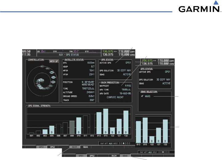
Figure 1-19 |
GPS Status Page |
The GPS Status Page provides the following information:
• Satellite constellation diagram
Satellites currently in view are shown at their respective positions on a sky view diagram. The sky view is always in a north-up orientation, with the outer circle representing the horizon, the inner circle representing 45° above the horizon, and the center point showing the position directly overhead.
Each satellite is represented by an oval containing the Pseudo-random noise (PRN) number (i.e., satellite identification number). Satellites whose signals are currently being used are represented by solid ovals.
• Satellite signal information status
The accuracy of the aircraft’s GPS fix is calculated using Estimated Position Uncertainty (EPU), Dilution of Precision (DOP), and horizontal and vertical figures of merit (HFOM and VFOM). EPU is the radius of a circle centered on an estimated horizontal position in which actual position has 95% probability of laying. EPU is a statistical error indication and not an actual error measurement.
DOP measures satellite geometry quality (i.e., number of satellites received and where they are relative to each other) on a range from 0.0 to 9.9, with lower numbers denoting better accuracy. HFOM and VFOM, measures of horizontal and vertical position uncertainty, are the current 95% confidence horizontal and vertical accuracy values reported by the GPS receiver.
The current calculated GPS position, time, altitude, ground speed, and track for the aircraft are displayed below the satellite signal accuracy measurements.
1-24 |
Garmin G1000 Pilot’s Guide for Cessna Nav III |
190-00498-02 Rev.A |

SYSTEM OVERVIEW
• GPS receiver status
The GPS solution type (ACQUIRING, 2D NAV, 2D DIFF NAV, 3D NAV, 3D DIFF NAV) for the active GPS receiver (GPS1 or GPS2) is shown in the upper right of the GPS Status Page. When the receiver is in the process of acquiring enough satellite signals for navigation, the receiver uses satellite orbital data (collected continuously from the satellites) and last known position to determine the satellites that should be in view. ACQUIRING is indicated as the solution until a sufficient number of satellites have been acquired for computing a solution.
When the receiver is in the process of acquiring a 3D navigational GPS solution, 3D NAV is indicated as the solution until the 3D differential fix has finished acquisition. SBAS (Satellite-Based Augmentation System) will indicate INACTIVE. When acquisition is complete, the solution status will indicate 3D DIFF NAV and SBAS will indicate ACTIVE.
•RAIM (Receiver Autonomous Integrity Monitoring) Prediction (RAIM Softkey is selected on WAAS enabled systems)(Default on non-WAAS systems)
In G1000 systems with WAAS enabled, performing a RAIM prediction will not be necessary in most cases. However, in some cases, the selected approach may be outside the WAAS coverage area and it may be necessary to perform a RAIM prediction for the intended approach.
Receiver Autonomous Integrity Monitoring (RAIM) is a GPS receiver function that performs a consistency check on all tracked satellites. RAIM ensures that the available satellite geometry allows the receiver to calculate a position within a specified RAIM protection limit (2.0 nautical miles for oceanic and enroute, 1.0 nm for terminal, and 0.3 nm for non-precision approaches). During oceanic, enroute, and terminal phases of flight, RAIM is available nearly 100% of the time.
The RAIM prediction function also indicates whether RAIM is available at a specified date and time. RAIM computations predict satellite coverage within ±15 min of the specified arrival date and time.
Because of the tighter protection limit on approaches, there may be times when RAIM is not available. The G1000 automatically monitors RAIM and warns with an alert message when it is not available. If RAIM is not predicted to be available for the final approach course, the approach does not become active, as indicated by the messages “Approach is not active” and “RAIM not available from FAF to MAP”. If RAIM is not available when crossing the FAF, the missed approach procedure must be flown.
Predicting RAIM availability:
1)Select the GPS Status Page.
2)If necessary, select the RAIM Softkey.
3)Press the FMS Knob. The ‘WAYPOINT’ field is highlighted.
4)Turn the small FMS Knob to display the Waypoint Information Window.
5)Enter the desired waypoint:
a)Use the FMS Knob to enter the desired waypoint by identifier,facility,or city name and press the ENT Key. Refer to Section 1.7 for instructions on entering alphanumeric data into the G1000.
OR:
a)Use the large FMS Knob to scroll to the Most Recent Waypoints List.
b)Use the small FMS Knob to highlight the desired waypoint in the list and press the ENT Key. The G1000 automatically fills in the identifier, facility, and city fields with the information for the selected waypoint.
190-00498-02 Rev.A |
Garmin G1000 Pilot’s Guide for Cessna Nav III |
1-25 |

SYSTEM OVERVIEW
c)Press the ENT Key to accept the waypoint entry. OR:
a)To use the present position, press the MENU Key.
b)With ‘Set WPT to Present Position’ highlighted, press the ENT Key.
c)Press the ENT Key to accept the waypoint entry.
6)Use the FMS Knob to enter an arrival time and press the ENT Key.
7)Use the FMS Knob to enter an arrival date and press the ENT Key.
8)With the cursor highlighting ‘COMPUTE RAIM?’, press the ENT Key. Once RAIM availability is computed, one of the following is displayed:
•‘COMPUTE RAIM?’—RAIM has not been computed for the current waypoint, time, and date combination
•‘COMPUTING AVAILABILITY’—RAIM calculation in progress
•‘RAIM AVAILABLE’—RAIM is predicted to be available for the specified waypoint, time, and date
•‘RAIM NOT AVAILABLE’—RAIM is predicted to be unavailable for the specified waypoint, time, and date
• SBAS Selection (SBAS Softkey is selected on WAAS enabled systems)
In certain situations, such as when the aircraft is outside or on the fringe of the WAAS coverage area, it may be desireable to disable WAAS (although it is not recommended). When disabled, the SBAS field in the GPS Status box will indicate DISABLED.
Disabling WAAS:
1)Select the GPS Status Page.
2)If necessary, select the SBAS Softkey.
3)Press the FMS Knob. ‘WAAS’ is highlighted.
4)Press the ENT Key to uncheck the box.
5)Press the FMS Knob to remove the cursor.
•GPS Satellite Signal Strengths
The GPS Status Page can be helpful in troubleshooting weak (or missing) signal levels due to poor satellite coverage or installation problems. As the GPS receiver locks onto satellites, a signal strength bar is displayed for each satellite in view, with the appropriate satellite PRN number (01-32 or 120-138 for WAAS) below each bar. The progress of satellite acquisition is shown in three stages, as indicated by signal bar appearance:
-No signal strength bar—Receiver is looking for the indicated satellite
-Hollow signal strength bar—Receiver has found the satellite and is collecting data
-Solid signal strength bar—Receiver has collected the necessary data and the satellite signal can be used
-Checkered signal strength bar—Receiver has excluded the satellite (Fault Detection and Exclusion)
-“D” indication—Denotes the satellite is being used as part of the differential computations
Each satellite has a 30-second data transmission that must be collected (signal strength bar is hollow) before the satellite may be used for navigation (signal strength bar becomes solid).
1-26 |
Garmin G1000 Pilot’s Guide for Cessna Nav III |
190-00498-02 Rev.A |