

- •Section 1 System Overview
- •1.1 System Description
- •1.2 Line Replaceable Units (LRU)
- •1.3 G1000 Controls
- •PFD/MFD Controls
- •Audio Panel Controls
- •1.4 Secure Digital (SD) Cards
- •1.5 System Power-up
- •1.6 System Operation
- •Normal Display Operation
- •Reversionary Display Operation
- •AHRS Operation
- •G1000 System Annunciations
- •Softkey Function
- •GPS Receiver Operation
- •1.7 Accessing G1000 Functionality
- •Menus
- •MFD Page Groups
- •MFD System Pages
- •Electronic Checklists (Optional)
- •1.8 Display Backlighting
- •Automatic Adjustment
- •Manual Adjustment
- •Section 2 flight Instruments
- •2.1 Flight Instruments
- •Airspeed Indicator
- •Attitude Indicator
- •Altimeter
- •Vertical Speed Indicator (VSI)
- •Vertical Deviation, Glideslope, & Glidepath Indicators
- •Horizontal Situation Indicator (HSI)
- •Course Deviation Indicator (CDI)
- •2.2 Supplemental Flight Data
- •Generic Timer
- •Outside Air Temperature
- •Wind Data
- •System Time
- •Vertical Navigation (VNV) Indications
- •2.3 PFD Annunciations and Alerting Functions
- •System Alerting
- •Traffic Annunciation
- •TAWS Annunciations
- •Low Altitude Annunciation
- •Altitude Alerting
- •Minimum Descent Altitude/Decision Height Alerting
- •Marker Beacon Annunciations
- •2.4 Abnormal Operations
- •Abnormal GPS Conditions
- •Unusual Attitudes
- •Section 3 Engine Indication System (EIS)
- •3.1 Engine Display
- •3.2 Lean Display
- •3.3 System Display
- •Section 4 audio panel and CNS
- •4.1 Overview
- •PFD/MFD Controls and Frequency Display
- •Audio Panel Controls
- •4.2 COM Operation
- •COM Transceiver Selection and Activation
- •COM Transceiver Manual Tuning
- •Quick-Tuning and Activating 121.500 MHz
- •Auto-tuning the COM Frequency
- •Frequency Spacing
- •Automatic Squelch
- •Volume
- •4.3 NAV Operation
- •NAV Radio Selection and Activation
- •NAV Receiver Manual Tuning
- •Auto-tuning the NAV Frequency
- •Marker Beacon Receiver
- •DME Tuning (Optional)
- •4.4 GTX 33 Mode S Transponder
- •Transponder Controls
- •Transponder Mode Selection
- •Entering a Transponder Code
- •IDENT Function
- •Flight ID Reporting
- •4.5 Additional Audio Panel Functions
- •Power-Up
- •Mono/Stereo Headsets
- •Speaker
- •Intercom
- •Clearance Recorder and Player
- •Entertainment Inputs
- •4.6 Audio Panel Preflight Procedure
- •4.7 Abnormal Operation
- •Stuck Microphone
- •COM Tuning Failure
- •Audio Panel Fail-Safe Operation
- •Reversionary Mode
- •Section 5 GPS Navigation
- •5.1 Introduction
- •5.2 Navigation Map (MFD)
- •Navigation Map Page
- •5.3 PFD Inset Map and Windows
- •Inset Map
- •PFD Windows
- •5.4 Direct-to-Navigation (MFD)
- •Selecting a Direct-to Waypoint
- •Clearing Vertical Constraints
- •Specifying a Course to a Waypoint
- •Canceling Direct-to Navigation
- •Direct-to Navigation Shortcuts
- •5.5 Direct-to-Navigation (PFD)
- •5.6 Airport Information (MFD)
- •Duplicate Waypoints
- •Additional Airport Runway Information
- •5.7 Intersection Information (MFD)
- •5.8 NDB Information (MFD)
- •5.9 VOR Information (MFD)
- •5.10 User Waypoint Information (MFD)
- •5.11 Nearest Airports (MFD)
- •5.12 Nearest Intersections (MFD)
- •5.13 Nearest NDB (MFD)
- •5.14 Nearest VOR (MFD)
- •5.15 Nearest User Waypoint (MFD)
- •5.16 Nearest Airspaces
- •5.17 Nearest Airports (PFD)
- •5.18 Flight Planning (MFD)
- •Airways/Jetways
- •Display of Airways on the Flight Plan Page
- •Vertical Navigation (VNV)
- •Navigating an Example Flight Plan
- •Parallel Track (PTK)
- •5.19 Flight Planning (PFD)
- •Operations
- •5.20 Procedures (MFD)
- •Leg Types Supported by the G1000
- •5.21 Procedures (PFD)
- •Operations
- •5.22 ABNORMAL OPERATION
- •Dead Reckoning
- •Section 6 Hazard Avoidance
- •6.1 XM Satellite Weather (Service Optional)
- •Activating XM Satellite Services
- •Using XM SATELLITE Weather Products
- •Weather Softkeys on the Weather Data Link Page
- •Setting Up the Weather Data Link Page
- •XM Satellite Weather on the Navigation Map
- •6.2 WX-500 Stormscope (Optional)
- •Setting Up Stormscope on the Navigation Map
- •Selecting the Stormscope Page
- •6.3 Terrain Proximity
- •Requirements
- •GPS Position and GPS-MSL Altitude
- •Displaying Terrain Proximity Data
- •Terrain Proximity Symbols
- •Terrain Proximity Page
- •Navigation Map Page
- •6.4 TAWS (Optional)
- •Requirements
- •TAWS Alerting
- •Using TAWS
- •TAWS Symbols
- •TAWS Alerts
- •6.5 Traffic
- •Traffic Information Service (TIS)
- •Honeywell KTA 870 TAS System (Optional)
- •ADS-B Traffic (Optional)
- •Section 7 Automatic Flight Control System
- •7.1 AFCS Controls
- •7.2 Flight Director Operation
- •Command Bars
- •Activating the Flight Director
- •7.3 Flight Director Modes
- •Pitch Modes
- •Roll Modes
- •7.4 Autopilot Operation
- •Engaging the Autopilot
- •Control Wheel Steering
- •Disengaging the Autopilot
- •7.5 Example Procedures
- •Departure
- •Intercepting a VOR Radial
- •Flying a Flight Plan/GPS Course
- •Descent
- •Approach
- •Go Around/Missed Approach
- •7.6 AFCS Annunciations and Alerts
- •AFCS Status Alerts
- •Overspeed Protection
- •Section 8 Additional Features
- •8.1 SafeTaxi
- •SafeTaxi Cycle Number and Revision
- •8.2 ChartView
- •ChartView Softkeys
- •Terminal Procedures Charts
- •Chart Options
- •Day/Night View
- •ChartView Cycle Number and Expiration Date
- •8.3 FliteCharts
- •FliteCharts Softkeys
- •Terminal Procedures Charts
- •Chart Options
- •Day/Night View
- •FliteCharts Cycle Number and Expiration Date
- •8.4 XM Radio Entertainment (Optional)
- •XM Satellite Radio Service
- •XM Service Activation
- •Using XM Radio
- •Automatic Audio Muting
- •8.5 Abnormal Operation
- •Annunciations and Alerts
- •Alert Level Definitions
- •NAV III Aircraft Alerts
- •CO Guardian Messages
- •G1000 System Annunciations
- •Other G1000 Aural Alerts
- •G1000 System Message Advisories
- •AFCS Alerts
- •TAWS ALERTS
- •TAWS System Status Annunciations
- •SD Card Use
- •Jeppesen Databases
- •Garmin Databases
- •Glossary
- •Frequently Asked Questions
- •General TIS Information
- •Introduction
- •TIS vs. TAS/TCAS
- •TIS Limitations
- •Map Symbols
- •Index

GPS NAVIGATION
NAVIGATING AN EXAMPLE FLIGHT PLAN
The following discussion is an example of navigating a flight plan with the WAAS capable GPS system while the G1000 provides vertical guidance through descents. A lateral flight plan (LNAV) would be navigated in much the same way, but would not include vertical guidance when the final approach course is active.
The example is a flight plan from KMKC to KCOS filed using the TIFTO2 departure, various Victor Airways, and the DBRY1 arrival with the transition at TBE. Enroute altitude will be 12,000 feet. An LPV (WAAS) approach will be selected for runway 35R. A missed approach will be executed at the Missed Approach Point (MAP). A few enroute changes are demonstrated.
NOTE: If the loaded arrival procedure has published altitudes contained in the navigation database, these are for turbojet aircraft only. Accept or change these values as desired to meet the requirements of the clearance.
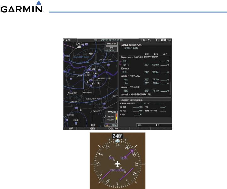
1)Prior to departure, the TIFTO2 departure, the airways, and the DBRY1 arrival at KCOS are loaded. See the Procedures section for loading departures and arrivals. Note the magenta arrow in Figure 5-86 indicating the active departure leg.
After takeoff,ATC assigns a heading of 240º.
5-96 |
Garmin G1000 Pilot’s Guide for Cessna Nav III |
190-00498-02 Rev.A |
GPS NAVIGATION
2)Figure 5-86 shows the aircraft on the assigned heading of 240º. ‘TERM’ (Terminal) is the current CDI flight phase displayed on the HSI indicating 1.0 nm CDI scaling.
Figure 5-86 Assigned Heading of 240º
190-00498-02 Rev.A |
Garmin G1000 Pilot’s Guide for Cessna Nav III |
5-97 |
GPS NAVIGATION
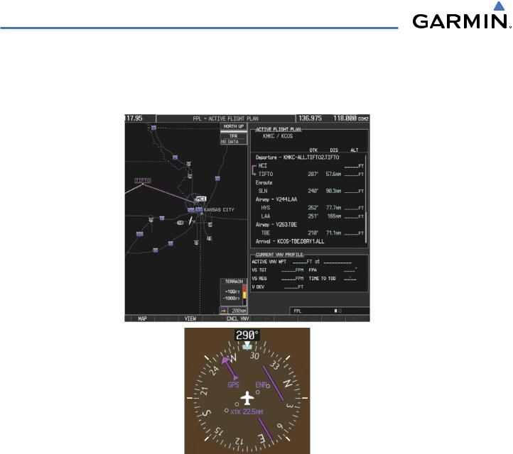
3)ATC now assigns routing to joinV4. A heading of 290º is assigned to interceptV4. The aircraft turns to heading 290° as seen in Figure 5-87. Note the current CDI flight phase is now ENR (Enroute). When the aircraft reached 30 nautical miles from the departure point, the flight phase changed from TERM to ENR on the HSI and CDI scaling changed to 2.0 nm.
Figure 5-87 Assigned Heading of 290º
5-98 |
Garmin G1000 Pilot’s Guide for Cessna Nav III |
190-00498-02 Rev.A |

GPS NAVIGATION
4)V4 will now be entered into the flight plan.
a)Press the FMS Knob to activate the cursor.
b)Turn the large FMS Knob to highlight the desired entry point as shown in Figure 5-88. The V4 entry will be placed immediately above the highlighted waypoint..
Figure 5-88 Begin Adding V4 to the Flight Plan
190-00498-02 Rev.A |
Garmin G1000 Pilot’s Guide for Cessna Nav III |
5-99 |
GPS NAVIGATION
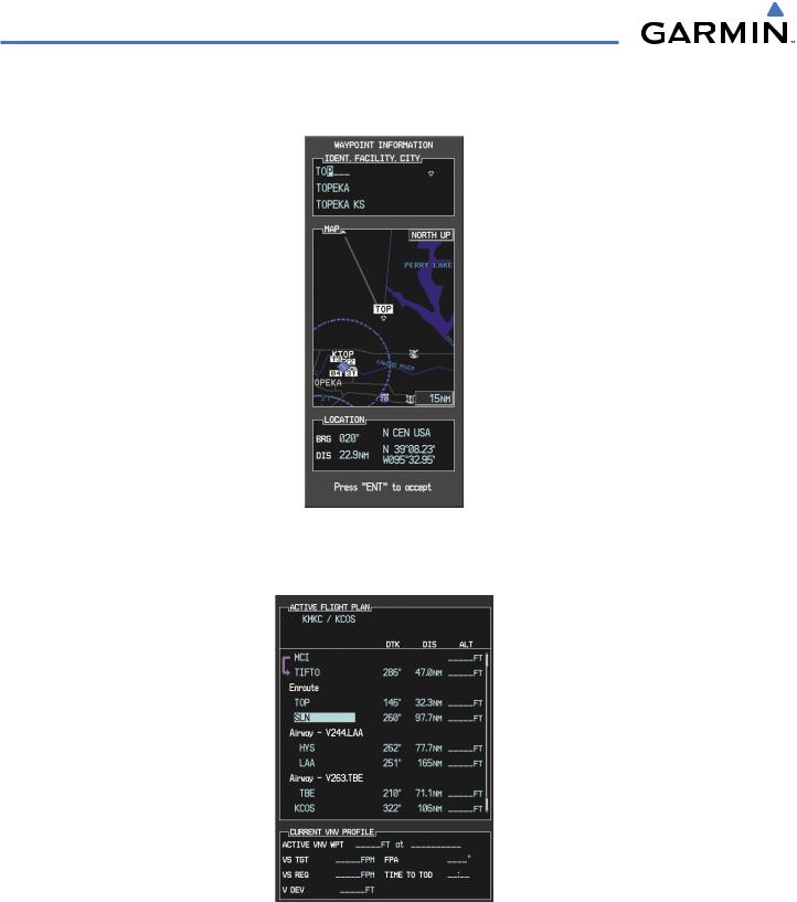
c)Turn the small FMS Knob to display the Waypoint Information Window. Enter the desired beginning point for V4 leg, in this example,Topeka VOR (TOP) will be used as shown in Figure 5-89.
Figure 5-89 Entering V4 Entry Point
d) Press the ENT Key. TOP is now inserted into the flight plan as in Figure 5-90.
Figure 5-90 TOP Inserted into the Flight Plan
e)With SLN still highlighted as in Figure 5-90, turn the small FMS Knob to the right. The Waypoint Information Page is displayed and the LD AIRWY Softkey is now available.
f)Press the LD AIRWY Softkey to display the list of available airways for TOP as seen in Figure 5-91.
5-100 |
Garmin G1000 Pilot’s Guide for Cessna Nav III |
190-00498-02 Rev.A |
GPS NAVIGATION
Figure 5-91 List of Available Airways for TOP
g)Turn either FMS Knob to highlight V4 in the list as seen in Figure 5-91.
h)Press the ENT Key. The list of V4 airway exit points is now displayed as in Figure 5-92.
Figure 5-92 List of Available Exits for V4
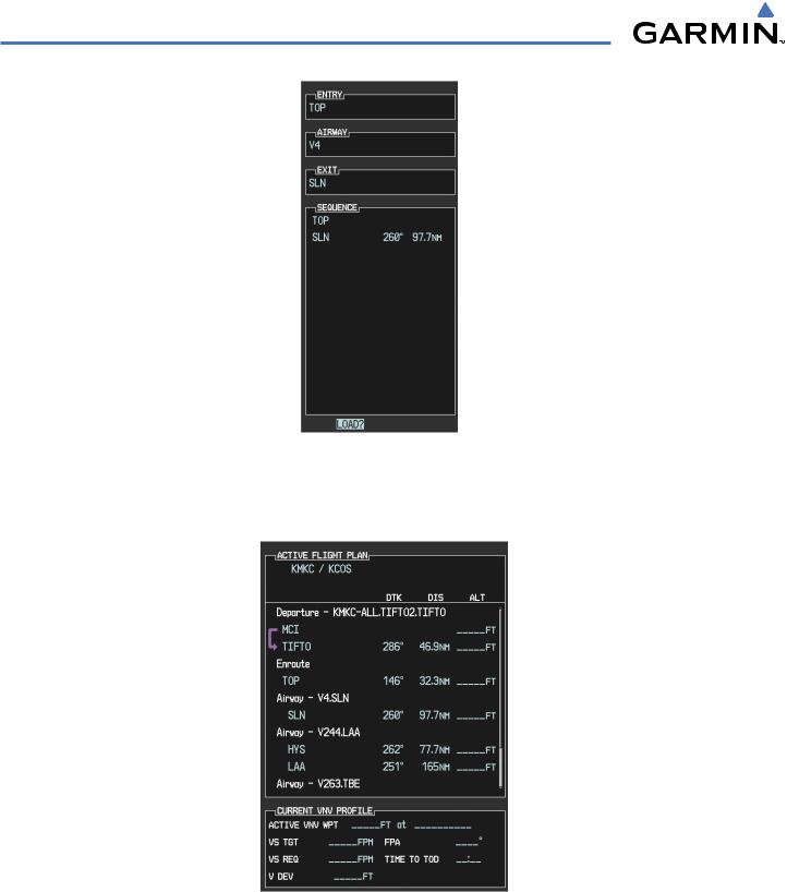
i)If necessary, turn either FMS Knob to select the desired exit. In this case SalinaVOR (SLN) is selected as seen in Figure 5-92.
j)Press the ENT Key. The selected airway and exit are displayed the prompt “LOAD?” highlighted as in Figure 5-93.
190-00498-02 Rev.A |
Garmin G1000 Pilot’s Guide for Cessna Nav III |
5-101 |
GPS NAVIGATION
Figure 5-93 Ready to Load V4
k)Press the ENT Key.
l)V4 is now loaded into the flight plan as shown in Figure 5-94.
Figure 5-94 V4 is Loaded in the Flight Plan
5)V4 will now be made the active leg of the flight plan.
a)Press the FMS Knob to activate the cursor.
5-102 |
Garmin G1000 Pilot’s Guide for Cessna Nav III |
190-00498-02 Rev.A |

GPS NAVIGATION
b)Turn the large FMS Knob to highlight SLN. The TO waypoint of the leg is selected in order to activate the leg.
c)Press the ACT LEG Softkey. The confirmation window is now displayed as in Figure 5-95. Note theTOP to SLN leg is actually part of V4.
Figure 5-95 Comfirm Active Leg
d)Verify the displayed leg is the desired leg and press the ENT Key. Note in Figure 5-96, the magenta arrow in the flight plan window and magenta line on the map indicating V4 is now the active flight plan leg.
Figure 5-96 V4 Now Active Leg
190-00498-02 Rev.A |
Garmin G1000 Pilot’s Guide for Cessna Nav III |
5-103 |

GPS NAVIGATION
6)The aircraft continues on heading 290º. When 2.0 nm from the intercept, the XTK will disappear from the HSI and the CDI will be positioned on the last dot indicating a 2.0 nm distance from the centerline of the next course.
7)As the CDI approaches center, the aircraft turns onto the active leg as seen in Figure 5-97.
Figure 5-97 Turn on to Active Leg
5-104 |
Garmin G1000 Pilot’s Guide for Cessna Nav III |
190-00498-02 Rev.A |

GPS NAVIGATION
8)At SLN, Victor Airway 244 (V244) will be intercepted. Turn prompts will be displayed in the PFD Navigation Status Box as seen in Figure 5-98.
Figure 5-98 Turn to Intercept V244
9) As seen in Figure 5-99,V244 is now the active flight plan leg.
Figure 5-99 V244 Now Active Leg
190-00498-02 Rev.A |
Garmin G1000 Pilot’s Guide for Cessna Nav III |
5-105 |
GPS NAVIGATION
10) At Lamar VOR (LAA) V263 will be intercepted. See Figure 5-100.
Figure 5-100 HYS to LAA Leg Active
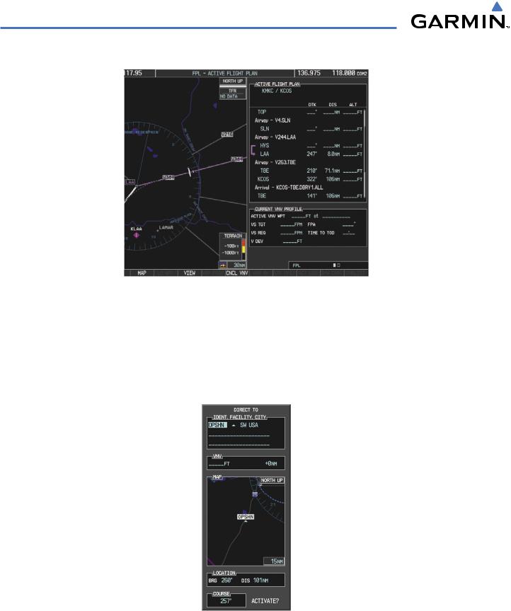
11)ATC grants clearance to proceed direct to OPSHN intersection to begin the arrival procedure and issues a crossing altitude restriction of 10,000 feet at OPSHN.
a)Press the FMS Knob to activate the cursor.
b)Turn the large FMS Knob to select OPSHN in the flight plan list.
c)Press the Direct-to ( ) Key. The Direct-to Window is now displayed as shown in Figure 5-101.
Figure 5-101 Direct To OPSHN
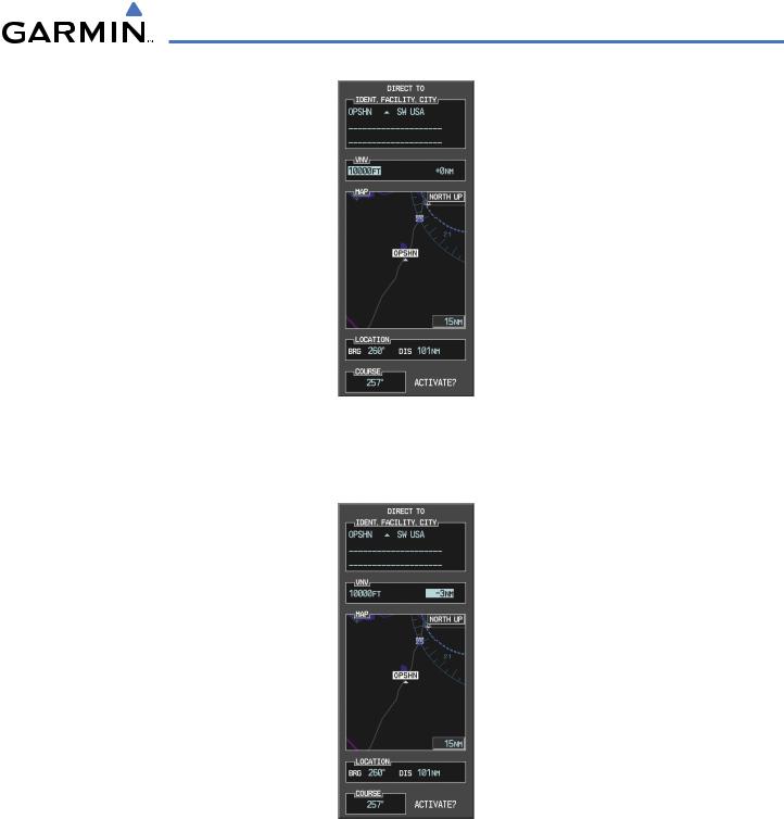
d) Turn the large FMS Knob to place the cursor in the VNV altitude field as shown in Figure 5-102.
5-106 |
Garmin G1000 Pilot’s Guide for Cessna Nav III |
190-00498-02 Rev.A |
GPS NAVIGATION
Figure 5-102 Enter VNV Altitude
e)An altitude of 10,000 feet is entered as requested by ATC.
f)Press the ENT Key. The cursor is now displayed in the VNV offset field as shown in Figure 5-103.
Figure 5-103 Enter VNV Offset Distance
g)Enter the offset, or distance from the waypoint at which the selected altitude will be reached. In this case, three miles prior to OPSHN is entered. In other words, the G1000 will give vertical guidance so the aircraft will arrive at an altitude of 10,000 feet three miles prior to OPSHN.
190-00498-02 Rev.A |
Garmin G1000 Pilot’s Guide for Cessna Nav III |
5-107 |
GPS NAVIGATION
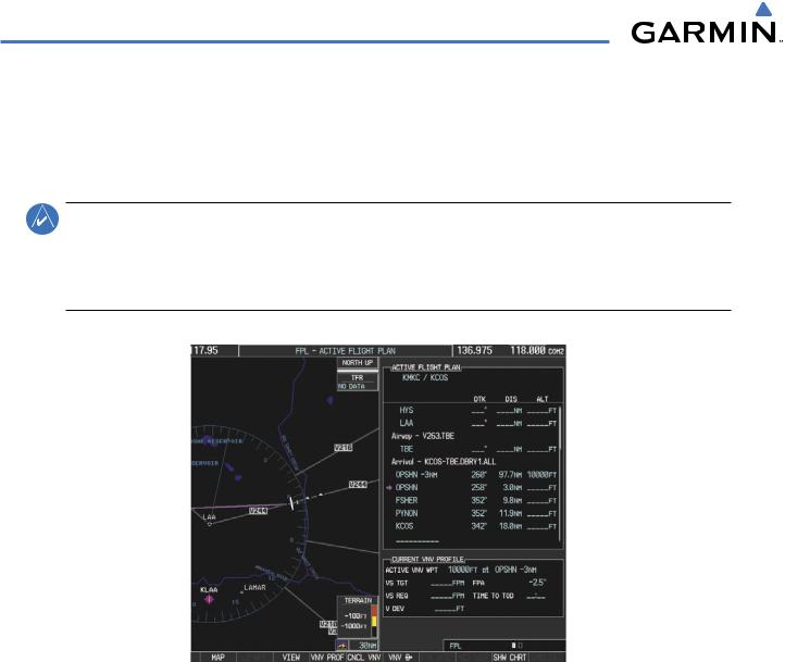
h)Press the ENT Key twice to activate the direct-to. Note, in Figure 5-104, the magenta arrow in the Active Flight Plan Window indicating the direct-to OPSHN after the offset waypoint for OPSHN. The preceding offset waypoint indicates the offset distance and altitude that was previously entered. The remaining waypoints in the loaded arrival procedure have no database specified altitudes, therefore, dashes are displayed. Keep the CDI centered and maintain a track along the magenta line to OPSHN.
NOTE: If the loaded arrival procedure has waypoints with altitude constraints retrieved from the database, those altitudes will be displayed as white numerals. This indicates the altitudes will not be used by the system for vertical guidance until manually accepted by the pilot. To accept the displayed altitude, place the cursor over the altitude and press the ENT Key. The altitude entry will then change to light blue numerals, indicating the altitude will now be
used by the system for providing vertical guidance.
Figure 5-104 Direct-to Active
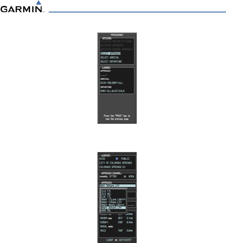
12)While proceeding to OPSHN, the LPV approach to runway 35R is preferred and will be used.
a)Press the PROC Key to display the Procedures Window.
If the GPS system is not WAAS capable, or WAAS is not available, the LPV approach will not be displayed in the list of available approaches. Selecting the LNAV approach for runway 35R will give vertical guidance up to the IAF.
5-108 |
Garmin G1000 Pilot’s Guide for Cessna Nav III |
190-00498-02 Rev.A |
GPS NAVIGATION
b) ‘SELECT APPROACH’ should be highlighted as shown in Figure 5-105.
Figure 5-105 Proceudures Window
c)Press the ENT Key. A list of available approaches for the destination airport will be displayed as in Figure 5- 106.
Figure 5-106 List of Available Approaches
d)Turn either FMS Knob to select the LPV approach for 35R as shown in Figure 5-106.
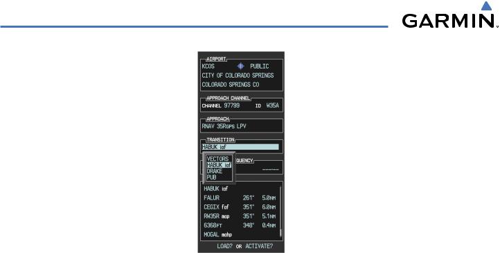
e)Press the ENT Key. A list of available transitions for the selected approach is displayed as shown on Figure 5- 107.
190-00498-02 Rev.A |
Garmin G1000 Pilot’s Guide for Cessna Nav III |
5-109 |
GPS NAVIGATION
Figure 5-107 List of Available Transitions
e)Turn either FMS Knob to select the desired transition. In this case, the Initial Approach Fix (IAF) at HABUK will be used.
f)Press the ENT Key.
5-110 |
Garmin G1000 Pilot’s Guide for Cessna Nav III |
190-00498-02 Rev.A |
GPS NAVIGATION
g)With ‘LOAD?’ highlighted, again press the ENT Key. The selected approach is added to the flight plan as seen in Figure 5-108.
Figure 5-108 Loaded Approach
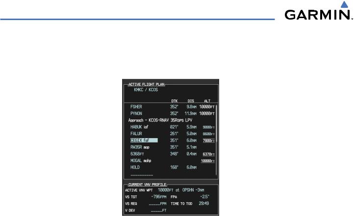
13)Note the altitude constraints associated with each of the approach waypoints as seen in Figure 5-108. These altitudes are loaded from the database and are displayed as light blue text, indicating these values are “designated” for use in computing vertical deviation guidance.
If it is desirable not to use the displayed altitude for calculating vertical deviation guidance, perform the following:
a)Press the FMS Knob to activate the cursor.
b)Turn the small FMS Knob to highlight the desired altitude.
c)Press the CLR Key.
d)Press the FMS Knob to deactivate the cursor.
After making the altitude “non-designated”, it is displayed as white text.
190-00498-02 Rev.A |
Garmin G1000 Pilot’s Guide for Cessna Nav III |
5-111 |
GPS NAVIGATION
Altitude constraint values associated with the Final Approach Fix (FAF) and waypoints beyond the FAF cannot be designated for vertical guidance. These altitude values will always be displayed as white text, as in Figure 5-109. Vertical guidance to the FAF and on to the Missed Approach Point (MAP) is given using the WAAS GPS altitude source, therefore, the displayed altitude values are for reference only.
Figure 5-109 Vertical Guidance is Active to the FAF
14)As the aircraft approaches OPSHN, it may be desirable to adjust how fast, or steep, the upcoming descent will be. The default Flight Path Angle (FPA) is -2.5 degrees and a required vertical speed will be computed to maintain the -2.5 FPA. To change the vertical flight path, perform the following steps.
5-112 |
Garmin G1000 Pilot’s Guide for Cessna Nav III |
190-00498-02 Rev.A |
GPS NAVIGATION
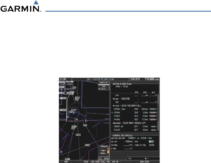
a)Press the VNV PROF Softkey to place the cursor in the target vertical speed field (VS TGT) as shown in Figure 5-110.
b)At this point, the descent vertical speed can be selected, or the FPA can be selected. Turn the large FMS Knob to select the desired selection field, then turn the small FMS Knob to entered the desired value.
Note the information now displayed in the ‘CURRENT VNV PROFILE’ box. Also, note the offset waypoint and a gray circle labeled ‘TOD’ are now displayed on the map. The gray circle marks theTop of Descent (TOD). In this example, after passing the TOD point, vertical guidance will be provided that will result in a -3.0 degree FPA descent to an altitude of 10,000 feet at the offset waypoint.
Figure 5-110 Adjusting the Descent
c) Press the ENT Key.
190-00498-02 Rev.A |
Garmin G1000 Pilot’s Guide for Cessna Nav III |
5-113 |
GPS NAVIGATION
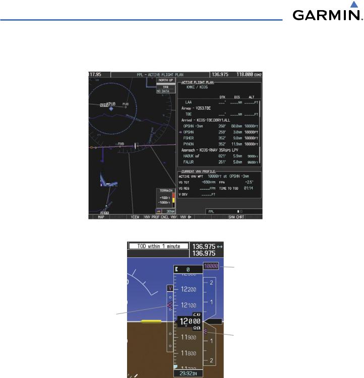
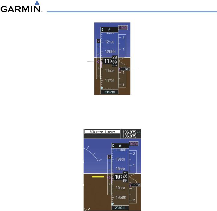
15)As seen in Figure 5-111, the aircraft is approaching TOD. Note the target vertical speed required to reach the selected altitude. TheVertical Deviation Indicator (VDI) and the RequiredVertical Speed Indicator (RVSI) are now displayed on the PFD as shown in Figure 5-112.
Figure 5-111 Approaching Top of Descent (TOD)
Target
Altitude
Vertical |
|
Deviation |
|
Indicator |
Required |
(VDI) |
Vertical |
|
Speed |
|
Indicator |
|
(RVSI) |
Figure 5-112 VDI & RVSI Upon Reaching Top of Descent (TOD)
16)Upon reachingTOD, a descent vertical speed is established which places theVSI pointer in line with the RVSI as shown in Figure 5-113.
5-114 |
Garmin G1000 Pilot’s Guide for Cessna Nav III |
190-00498-02 Rev.A |
GPS NAVIGATION
Keep Vertical |
Align Actual |
|
Deviation Pointer |
||
Vertical Speed |
||
Centered |
||
with Required |
||
|
Vertical Speed |
Figure 5-113 VDI & RVSI Showing Correctly Established Descent
17)When the aircraft is one minute from the bottom of descent (BOD) this will be annunciated as shown in Figure 5-114. Upon reaching the OPSHN offset waypoint (three miles before OPSHN), the aircraft will be at 10,000 feet.
Figure 5-114 Approaching Bottom of Descent (BOD) at OPSHN
190-00498-02 Rev.A |
Garmin G1000 Pilot’s Guide for Cessna Nav III |
5-115 |
GPS NAVIGATION
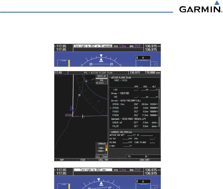
18)The aircraft is approaching OPSHN. The upcoming turn and next heading will be annunciated at the top left of the PFD as seen in Figure 5-115. Initiate the turn and maneuver the aircraft on a track through the turn radius to intercept the magenta line for the OPSHN to FSHER leg and center the CDI.
Figure 5-115 Turn to intercept OPSHN to FSHER Leg
5-116 |
Garmin G1000 Pilot’s Guide for Cessna Nav III |
190-00498-02 Rev.A |
GPS NAVIGATION
19)After passing OPSHN, the next leg of the arrival will turn magenta as shown in Figure 5-116. The magenta arrow in the flight plan list now indicates the OPSHN to FSHER leg of the arrival procedure is now active.
Figure 5-116 Tracking the OPSHN to FSHER Leg
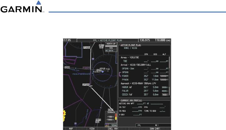
20)The flight continues through the arrival procedure to PYNON (see Figure 5-117). At a point 31 nautical miles from the destination airport, the phase of flight scaling for the CDI will change to Terminal Mode and is annunciated by displaying ‘TERM’ on the HSI.
There will be a descent to HABUK in the next leg. Note the TOD point on the map. Annunciations for the upcoming turn and descent, as well as the VDI and RVSI, appear on the PFD as the flight progresses.
190-00498-02 Rev.A |
Garmin G1000 Pilot’s Guide for Cessna Nav III |
5-117 |

GPS NAVIGATION
Figure 5-117 Approaching PYNON
5-118 |
Garmin G1000 Pilot’s Guide for Cessna Nav III |
190-00498-02 Rev.A |

GPS NAVIGATION
21)Upon passing PYNON the approach procedure will automatically become active. The approach may be activated at any point to proceed directly to the IAF. In this example, the aircraft has progressed through the final waypoint of the arrival and the flight plan has automatically sequenced to the IAF as the active leg, activating the approach procedure (see Figure 5-118).
Figure 5-118 Approach Leg is Now Active
To manually activate the approach procedure, perform the following steps:
a)Press the PROC Key.
b)Turn the large FMS Knob to highlight ‘ACTIVATE APPROACH’ as shown in Figure 5-119.
Figure 5-119 Activate Missed Approach
c)Press the ENT Key to activate the approach.
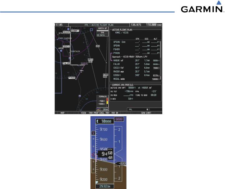
22)The IAF is the next waypoint. At the TOD, establish a descent vertical speed as previously discussed in Step 16. The aircraft altitude will be 9,000 feet upon reaching HABUK.
190-00498-02 Rev.A |
Garmin G1000 Pilot’s Guide for Cessna Nav III |
5-119 |
GPS NAVIGATION
Figure 5-120 Descending Turn to the Initial Approach Fix (IAF)
5-120 |
Garmin G1000 Pilot’s Guide for Cessna Nav III |
190-00498-02 Rev.A |
GPS NAVIGATION
23)After crossing FALUR the next waypoint is the FAF. The flight phase changes to LPV on the HSI indicating the current phase of flight is inApproach Mode and the approach type is LPV. CDI scaling changes accordingly and is used much like a localizer when flying an ILS approach. The RVSI is no longer displayed and the VDI changes to the Glidepath Indicator (as shown in Figure 5-121) when the final approach course becomes active.
Figure 5-121 Descending to the FAF
The descent continues through the FAF (CEGIX) using the Glidepath Indicator, as one would use a glideslope indicator, to obtain an altitude “AT” 7,800 feet at the FAF. Note the altitude restriction lines over and under (‘At’) the altitude in the ‘ALT’ field in Figure 5-121.
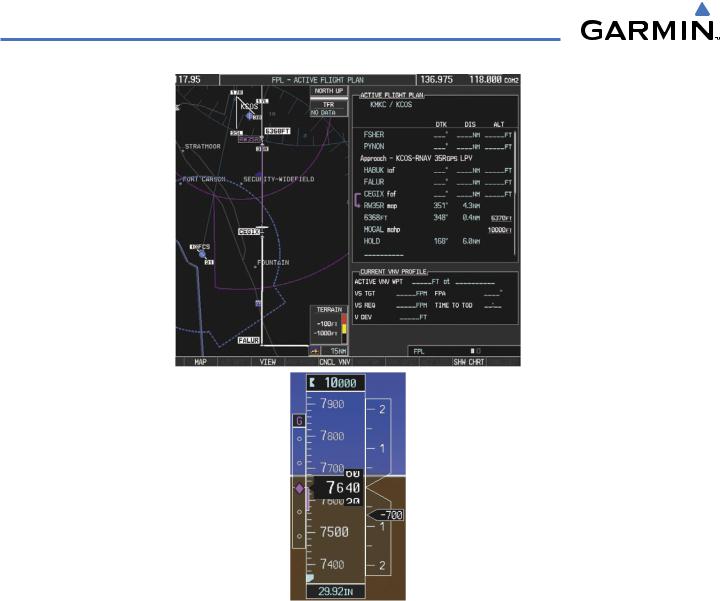
24)After crossing CEGIX, the aircraft continues following the glidepath to maintain the descent to “AT or ABOVE” 6,370 feet at the Missed Approach Point (MAP) (RW35R) as seen in Figure 5-122.
190-00498-02 Rev.A |
Garmin G1000 Pilot’s Guide for Cessna Nav III |
5-121 |
GPS NAVIGATION
Figure 5-122 Descending to the Missed Approach Point
In this missed approach procedure,the fix immediately following the MAP (in this case‘6368FT’) is not part of the published procedure. It is simply a fix that defines a leg which guides the aircraft along the runway centerline until the required altitude to make the first turn on the missed approach is exceeded. In this case, if the aircraft altitude is below the specified altitude (6,368 feet) after crossing the MAP, a direct-to will be established to this fix until an altitude of 6,368 feet reached. After reaching 6,368 feet, a direct-to will be established to the published fix (in this case MOGAL). If the aircraft altitude is above the specified altitude after crossing the MAP, a direct-to will be established to the published fix (MOGAL) to begin the missed approach procedure. The altitude constraint value defaults to 400 feet AGL when the fix is not part of the published procedure.
In some missed approach procedures this altitude fix may be part of the published procedure. For example, the procedure dictates a climb to 5,500 feet,then turn left and proceed to the MissedApproach Hold Point (MAHP). In this case,the altitude fix would be labeled‘5500FT’. Again,if the aircraft altitude is lower than this prescribed altitude, a direct-to will be established to this fix when the missed approach procedure is activated.
5-122 |
Garmin G1000 Pilot’s Guide for Cessna Nav III |
190-00498-02 Rev.A |
GPS NAVIGATION
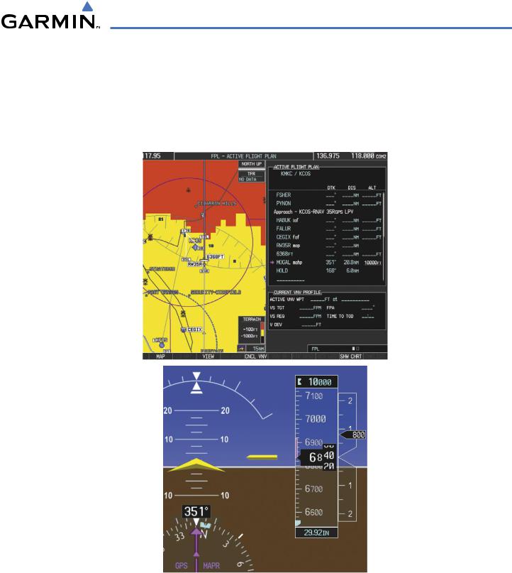
25)Upon reaching the MAP, it is decided to execute a missed approach. Automatic waypoint sequencing is suspended past the MAP. Press the SUSP Softkey on the PFD to resume automatic waypoint sequencing through the missed approach procedure.
A direct-to is initiated to MOGAL, which is the Missed Approach Hold Point (MAHP) as seen in Figure 5-123. The aircraft is climbing to 10,000 feet. The CDI flight phase now changes from LPV to MAPR as seen on the HSI.
Figure 5-123 Missed Approach Active
190-00498-02 Rev.A |
Garmin G1000 Pilot’s Guide for Cessna Nav III |
5-123 |
GPS NAVIGATION
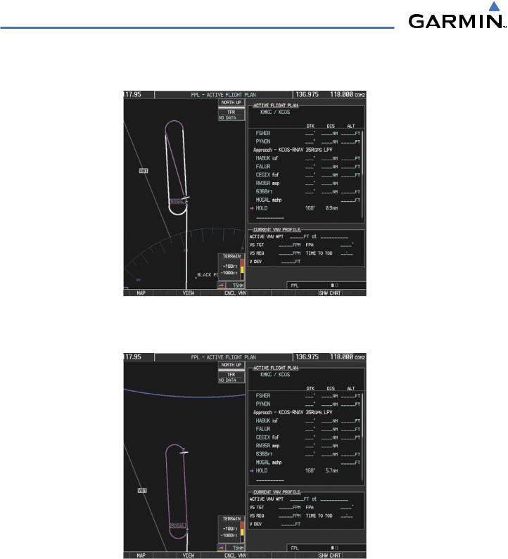
26)The aircraft continues climbing to “AT orABOVE” 10,000 feet at MOGAL. A holding pattern will be established at the MAHP (MOGAL) as shown in Figure 5-124.
Figure 5-124 Establishing the Holding Pattern
27) The aircraft maintains 10,000 feet while following the magenta line through the hold as in Figure 5-125.
Figure 5-125 Hold Established
5-124 |
Garmin G1000 Pilot’s Guide for Cessna Nav III |
190-00498-02 Rev.A |