

- •Chapter 1
- •1.1 Motivation
- •1.2 Objective of the Specification
- •1.3 Scope of the Document
- •1.4 Document Organization
- •Chapter 2
- •Chapter 3
- •3.1 Goals for the Universal Serial Bus
- •3.2 Taxonomy of Application Space
- •3.3 Feature List
- •Chapter 4
- •4.1 USB System Description
- •4.1.1 Bus Topology
- •4.2 Physical Interface
- •4.2.1 Electrical
- •4.2.2 Mechanical
- •4.3 Power
- •4.3.1 Power Distribution
- •4.3.2 Power Management
- •4.4 Bus Protocol
- •4.5 Robustness
- •4.5.1 Error Detection
- •4.5.2 Error Handling
- •4.6 System Configuration
- •4.6.1 Attachment of USB Devices
- •4.6.2 Removal of USB Devices
- •4.6.3 Bus Enumeration
- •4.7 Data Flow Types
- •4.7.1 Control Transfers
- •4.7.2 Bulk Transfers
- •4.7.3 Interrupt Transfers
- •4.7.4 Isochronous Transfers
- •4.7.5 Allocating USB Bandwidth
- •4.8 USB Devices
- •4.8.1 Device Characterizations
- •4.8.2 Device Descriptions
- •4.9 USB Host: Hardware and Software
- •4.10 Architectural Extensions
- •Chapter 5
- •5.1 Implementer Viewpoints
- •5.2 Bus Topology
- •5.2.1 USB Host
- •5.2.2 USB Devices
- •5.2.3 Physical Bus Topology
- •5.2.4 Logical Bus Topology
- •5.2.5 Client Software-to-function Relationship
- •5.3 USB Communication Flow
- •5.3.1 Device Endpoints
- •5.3.2 Pipes
- •5.4 Transfer Types
- •5.5 Control Transfers
- •5.5.1 Control Transfer Data Format
- •5.5.2 Control Transfer Direction
- •5.5.3 Control Transfer Packet Size Constraints
- •5.5.4 Control Transfer Bus Access Constraints
- •5.5.5 Control Transfer Data Sequences
- •5.6 Isochronous Transfers
- •5.6.1 Isochronous Transfer Data Format
- •5.6.2 Isochronous Transfer Direction
- •5.6.3 Isochronous Transfer Packet Size Constraints
- •5.6.4 Isochronous Transfer Bus Access Constraints
- •5.6.5 Isochronous Transfer Data Sequences
- •5.7 Interrupt Transfers
- •5.7.1 Interrupt Transfer Data Format
- •5.7.2 Interrupt Transfer Direction
- •5.7.3 Interrupt Transfer Packet Size Constraints
- •5.7.4 Interrupt Transfer Bus Access Constraints
- •5.7.5 Interrupt Transfer Data Sequences
- •5.8 Bulk Transfers
- •5.8.1 Bulk Transfer Data Format
- •5.8.2 Bulk Transfer Direction
- •5.8.3 Bulk Transfer Packet Size Constraints
- •5.8.4 Bulk Transfer Bus Access Constraints
- •5.8.5 Bulk Transfer Data Sequences
- •5.9 Bus Access for Transfers
- •5.9.1 Transfer Management
- •5.9.2 Transaction Tracking
- •5.9.3 Calculating Bus Transaction Times
- •5.9.4 Calculating Buffer Sizes in Functions and Software
- •5.9.5 Bus Bandwidth Reclamation
- •5.10 Special Considerations for Isochronous Transfers
- •5.10.1 Example Non-USB Isochronous Application
- •5.10.2 USB Clock Model
- •5.10.3 Clock Synchronization
- •5.10.4 Isochronous Devices
- •5.10.5 Data Prebuffering
- •5.10.6 SOF Tracking
- •5.10.7 Error Handling
- •5.10.8 Buffering for Rate Matching
- •Chapter 6
- •6.1 Architectural Overview
- •6.3 Cable
- •6.4 Cable Assembly
- •6.4.1 Detachable Cable Assemblies
- •6.4.3 Low-speed Captive Cable Assemblies
- •6.4.4 Prohibited Cable Assemblies
- •6.5.1 USB Icon Location
- •6.5.2 USB Connector Termination Data
- •6.5.3 Series “A” and Series “B” Receptacles
- •6.5.4 Series “A” and Series “B” Plugs
- •6.6.1 Description
- •6.6.2 Construction
- •6.6.3 Electrical Characteristics
- •6.6.4 Cable Environmental Characteristics
- •6.6.5 Listing
- •6.7 Electrical, Mechanical and Environmental Compliance Standards
- •6.7.1 Applicable Documents
- •6.8 USB Grounding
- •Chapter 7
- •7.1 Signaling
- •7.1.1 USB Driver Characteristics
- •7.1.2 Data Signal Rise and Fall
- •7.1.3 Cable Skew
- •7.1.4 Receiver Characteristics
- •7.1.5 Device Speed Identification
- •7.1.6 Input Characteristics
- •7.1.7 Signaling Levels
- •7.1.8 Data Encoding/Decoding
- •7.1.9 Bit Stuffing
- •7.1.10 Sync Pattern
- •7.1.11 Data Signaling Rate
- •7.1.12 Frame Interval and Frame Interval Adjustment
- •7.1.13 Data Source Signaling
- •7.1.14 Hub Signaling Timings
- •7.1.15 Receiver Data Jitter
- •7.1.16 Cable Delay
- •7.1.17 Cable Attenuation
- •7.1.18 Bus Turn-around Time and Inter-packet Delay
- •7.1.19 Maximum End-to-end Signal Delay
- •7.2 Power Distribution
- •7.2.1 Classes of Devices
- •7.2.2 Voltage Drop Budget
- •7.2.3 Power Control During Suspend/Resume
- •7.2.4 Dynamic Attach and Detach
- •7.3 Physical Layer
- •7.3.1 Regulatory Requirements
- •7.3.2 Bus Timing/Electrical Characteristics
- •7.3.3 Timing Waveforms
- •Chapter 8
- •8.1 Bit Ordering
- •8.2 SYNC Field
- •8.3 Packet Field Formats
- •8.3.1 Packet Identifier Field
- •8.3.2 Address Fields
- •8.3.3 Frame Number Field
- •8.3.4 Data Field
- •8.3.5 Cyclic Redundancy Checks
- •8.4 Packet Formats
- •8.4.1 Token Packets
- •8.4.2 Start-of-Frame Packets
- •8.4.3 Data Packets
- •8.4.4 Handshake Packets
- •8.4.5 Handshake Responses
- •8.5 Transaction Formats
- •8.5.1 Bulk Transactions
- •8.5.2 Control Transfers
- •8.5.3 Interrupt Transactions
- •8.5.4 Isochronous Transactions
- •8.6 Data Toggle Synchronization and Retry
- •8.6.1 Initialization via SETUP Token
- •8.6.2 Successful Data Transactions
- •8.6.3 Data Corrupted or Not Accepted
- •8.6.4 Corrupted ACK Handshake
- •8.6.5 Low-speed Transactions
- •8.7 Error Detection and Recovery
- •8.7.1 Packet Error Categories
- •8.7.2 Bus Turn-around Timing
- •8.7.3 False EOPs
- •8.7.4 Babble and Loss of Activity Recovery
- •Chapter 9
- •9.1 USB Device States
- •9.1.1 Visible Device States
- •9.1.2 Bus Enumeration
- •9.2 Generic USB Device Operations
- •9.2.1 Dynamic Attachment and Removal
- •9.2.2 Address Assignment
- •9.2.3 Configuration
- •9.2.4 Data Transfer
- •9.2.5 Power Management
- •9.2.6 Request Processing
- •9.2.7 Request Error
- •9.3 USB Device Requests
- •9.3.1 bmRequestType
- •9.3.2 bRequest
- •9.3.3 wValue
- •9.3.4 wIndex
- •9.3.5 wLength
- •9.4 Standard Device Requests
- •9.4.1 Clear Feature
- •9.4.2 Get Configuration
- •9.4.3 Get Descriptor
- •9.4.4 Get Interface
- •9.4.5 Get Status
- •9.4.6 Set Address
- •9.4.7 Set Configuration
- •9.4.8 Set Descriptor
- •9.4.9 Set Feature
- •9.4.10 Set Interface
- •9.4.11 Synch Frame
- •9.5 Descriptors
- •9.6 Standard USB Descriptor Definitions
- •9.6.1 Device
- •9.6.2 Configuration
- •9.6.3 Interface
- •9.6.4 Endpoint
- •9.6.5 String
- •9.7 Device Class Definitions
- •9.7.1 Descriptors
- •9.7.2 Interface(s) and Endpoint Usage
- •9.7.3 Requests
- •Chapter 10
- •10.1 Overview of the USB Host
- •10.1.1 Overview
- •10.1.2 Control Mechanisms
- •10.1.3 Data Flow
- •10.1.4 Collecting Status and Activity Statistics
- •10.1.5 Electrical Interface Considerations
- •10.2 Host Controller Requirements
- •10.2.1 State Handling
- •10.2.2 Serializer/Deserializer
- •10.2.3 Frame Generation
- •10.2.4 Data Processing
- •10.2.5 Protocol Engine
- •10.2.6 Transmission Error Handling
- •10.2.7 Remote Wakeup
- •10.2.8 Root Hub
- •10.2.9 Host System Interface
- •10.3 Overview of Software Mechanisms
- •10.3.1 Device Configuration
- •10.3.2 Resource Management
- •10.3.3 Data Transfers
- •10.3.4 Common Data Definitions
- •10.4 Host Controller Driver
- •10.5 Universal Serial Bus Driver
- •10.5.1 USBD Overview
- •10.5.2 USBD Command Mechanism Requirements
- •10.5.3 USBD Pipe Mechanisms
- •10.5.4 Managing the USB via the USBD Mechanisms
- •10.5.5 Passing USB Preboot Control to the Operating System
- •10.6 Operating System Environment Guides
- •Chapter 11
- •11.1 Overview
- •11.1.1 Hub Architecture
- •11.1.2 Hub Connectivity
- •11.2 Hub Frame Timer
- •11.2.1 Frame Timer Synchronization
- •11.2.2 EOF1 and EOF2 Timing Points
- •11.3 Host Behavior at End-of-Frame
- •11.3.1 Latest Host Packet
- •11.3.2 Packet Nullification
- •11.3.3 Transaction Completion Prediction
- •11.4 Internal Port
- •11.4.1 Inactive
- •11.4.2 Suspend Delay
- •11.4.3 Full Suspend (Fsus)
- •11.4.4 Generate Resume (GResume)
- •11.5 Downstream Ports
- •11.5.1 Downstream Port State Descriptions
- •11.6 Upstream Port
- •11.6.1 Receiver
- •11.6.2 Transmitter
- •11.7 Hub Repeater
- •11.7.1 Wait for Start of Packet from Upstream Port (WFSOPFU)
- •11.7.2 Wait for End of Packet from Upstream Port (WFEOPFU)
- •11.7.3 Wait for Start of Packet (WFSOP)
- •11.7.4 Wait for End of Packet (WFEOP)
- •11.8 Bus State Evaluation
- •11.8.1 Port Error
- •11.8.2 Speed Detection
- •11.8.3 Collision
- •11.9 Suspend and Resume
- •11.10 Hub Reset Behavior
- •11.10.1 Hub Receiving Reset on Upstream Port
- •11.11 Hub Port Power Control
- •11.11.1 Multiple Gangs
- •11.12 Hub I/O Buffer Requirements
- •11.12.1 Pull-up and Pull-down Resistors
- •11.12.2 Edge Rate Control
- •11.13 Hub Controller
- •11.13.1 Endpoint Organization
- •11.13.2 Hub Information Architecture and Operation
- •11.13.3 Port Change Information Processing
- •11.13.4 Hub and Port Status Change Bitmap
- •11.13.5 Over-current Reporting and Recovery
- •11.14 Hub Configuration
- •11.15 Descriptors
- •11.15.1 Standard Descriptors
- •11.15.2 Class-specific Descriptors
- •11.16 Requests
- •11.16.1 Standard Requests
- •11.16.2 Class-specific Requests
- •Index
Universal Serial Bus Specification Revision 1.1
Over-current Reporting Mode to indicate that power switching and over-current reporting are on a per port basis (these fields are in wHubCharacteristics.) Also, all bits in PortPwrCtrlMask must be set to 1b.
When an over-current condition occurs on an over-current protection device, the over-current is signaled on all ports that are protected by that device. When the over-current is signaled, all the ports in the group are placed in the Powered-off state, and the C_PORT_OVER-CURRENT field is set to 1B on all the ports. When port status is read from any port in the group, the PORT_OVER-CURRENT field will be set to 1b as long as the over-current condition exists. The C_PORT_OVER-CURRENT field must be cleared in each port individually.
When multiple ports share a power switch, setting PORT_POWER on any port in the group will cause the power to all ports in the group to turn on. It will not, however, cause the other ports in that group to leave the Powered-off state. When all the ports in a group are in the Powered-off state or the hub is not configured, the power to the ports is turned off.
If a hub implements both power switching and over-current, it is not necessary for the over-current groups to be the same as the power switching groups.
If an over-current condition occurs and power switches are present, then all power switches associated with an over-current protection circuit must be turned off. If multiple over-current protection devices are associate with a single power switch then that switch will be turned off when any of the over-current protection circuits indicates an over-current condition.
11.12 Hub I/O Buffer Requirements
All hub ports must be able to detect and generate all the bus signaling states described in Table 7-1. This requires that hub be able to independently drive and monitor the D+ and D- outputs on each of its ports. Each hub port must have single-ended receivers and transmitters on the D+ and D- lines as well as a differential receiver and transmitter. Details on voltage levels and drive requirements appear in Chapter 7.
11.12.1 Pull-up and Pull-down Resistors
Hubs, and the devices to which they connect, use a combination of pull-up and pull-down resistors to control D+ and D- in the absence of their being actively driven. These resistors establish voltage levels used to signal connect and disconnect and maintain the data lines at their idle values when not being actively driven. Each hub downstream port requires a pull-down resistor (Rpd) on each data line; the hub upstream port requires a pull-up resistor (Rpu) on its D+ line. Values for Rpu and Rpd appear in Chapter 7.
11.12.2 Edge Rate Control
Downstream hub ports must support transmission and reception of both low-speed and full-speed edge rates. The respective signaling specifications are given in Chapter 7. Edge rate on a downstream port must be selectable, based upon whether a downstream device was detected as being full-speed or low-speed. The hub upstream port always uses full-speed signaling, and its output buffers always operate with fullspeed edge rates and signal polarities.
11.13 Hub Controller
The Hub Controller is logically organized as shown in Figure 11-11.
256

Universal Serial Bus Specification Revision 1.1
UPSTREAM CONNECTION
Status Change |
ENDPOINT 0: |
|
Configuration |
||
Endpoint |
||
Information |
||
|
Port 1 |
Port N |
|
Port 2 |
Port 3 |
Figure 11-11. Example Hub Controller Organization
11.13.1 Endpoint Organization
The Hub Class defines one additional endpoint beyond Default Control Pipe, which is required for all devices: the Status Change endpoint. The host system receives port and hub status change notifications through the Status Change endpoint. The Status Change endpoint is an interrupt endpoint. If no hub or port status change bits are set, then the hub returns an NAK when the Status Change endpoint is polled. When a status change bit is set, the hub responds with data, as shown in Section 11.13.4, indicating the entity (hub or port) with a change bit set. The USB System Software can use this data to determine which status registers to access in order to determine the exact cause of the status change interrupt.
11.13.2 Hub Information Architecture and Operation
Figure 11-12 shows how status, status change, and control information relate to device states. Hub descriptors and Hub/Port Status and Control are accessible through the Default Control Pipe. The Hub descriptors may be read at any time. When a hub detects a change on a port or when the hub changes its own state, the Status Change endpoint transfers data to the host in the form specified in Section 11.13.4.
Hub or port status change bits can be set because of hardware or software events. When set, these bits remain set until cleared directly by the USB System Software through a ClearPortFeature() request or by a hub reset. While a change bit is set, the hub continues to report a status change when polled until all change bits have been cleared by the USB System Software.
257

Universal Serial Bus Specification Revision 1.1
Software (e.g., Hub |
Driver) |
Host |
|
|
|
|
|
Device Control
Status Information
(static)
Change Information (due to hardware events)
|
All |
Hardware Events |
|
Changes |
|
|
Status |
|
Hardware |
Events |
Change Device |
|
||
|
|
|
|
|
State |
Control Information |
Software Device |
(change device state) |
Control |
Figure 11-12. Relationship of Status, Status Change, and Control Information to Device States
The USB System Software uses the interrupt pipe associated with the Status Change endpoint to detect changes in hub and port status.
258
Universal Serial Bus Specification Revision 1.1
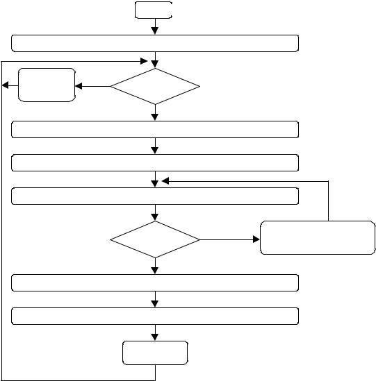
11.13.3 Port Change Information Processing
Hubs report a port's status through port commands on a per-port basis. The USB System Software acknowledges a port change by clearing the change state corresponding to the status change reported by the hub. The acknowledgment clears the change state for that port so future data transfers to the Status Change endpoint do not report the previous event. This allows the process to repeat for further changes (see Figure 11-13.)
Begin
System Software requests Interrupt Pipe notification for Status Change Information
Hub NAKs |
No |
Change Data |
|
status change |
|||
|
|
IN token |
Available ? |
|
Yes
Interrupt Pipe returns Hub and Port Status Change Bitmap
Interrupt Pipe notification retired
System Software reads Hub or Port status (for affected ports)
Yes |
|
Accumulate change information |
Any Changed |
|
System Software clears |
State? |
|
corresponding change state |
No |
|
|
System Software processes accumulated change information
Re-initialize Interrupt Pipe for Status Change endpoint
Return to beginning
Figure 11-13. Port Status Handling Method
11.13.4 Hub and Port Status Change Bitmap
The Hub and Port Status Change Bitmap, shown in Figure 11-14, indicates whether the hub or a port has experienced a status change. This bitmap also indicates which port(s) have had a change in status. The hub returns this value on the Status Change endpoint. Hubs report this value in byte-increments. That is, if a hub has six ports, it returns a byte quantity and reports a zero in the invalid port number field locations. the USB System Software is aware of the number of ports on a hub (this is reported in the hub descriptor)
259