

Universal Serial Bus Specification Revision 1.1
Hubs and certain full-speed functions need to track the frame interval. They also are required to have sufficient frame timing adjustment to compensate for their own frequency tolerance and track the host’s15 full-speed bit time variability.
7.1.13 Data Source Signaling
This section covers the timing characteristics of data produced and sent from a port (the data source). Section 7.1.14 covers the timing characteristics of data that is transmitted through the Hub Repeater section of a hub. In this section, TPERIOD is defined as the actual period of the data rate that can have a range as defined in Section 7.1.11.
7.1.13.1 Data Source Jitter
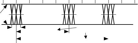
The source of data can have some variation (jitter) in the timing of edges of the data transmitted. The time between any set of data transitions is N * TPERIOD jitter time, where ‘N’ is the number of bits between the transitions. The data jitter is measured with the same load used for maximum rise and fall times and is measured at the crossover points of the data lines, as shown in Figure 7-26.
Crossover
Differential Points
Data Lines 
Jitter |
|
|
|
|
|
|
|
|
|
Integer multiples of TPERIOD |
|||
|
|
|
|
Consecutive |
|
|
|||||||
|
|
|
|
|
|
|
|
|
|
|
|
|
|
|
|
|
|
|
|
Transitions |
|
|
|
|
|
|
|
|
|
|
Paired |
|
|
|
|||||||
|
|
|
|
|
|
|
|
|
|
||||
|
|
|
|
|
|
|
|
Transitions |
|
|
|
||
|
|
|
|
|
|
|
|
|
|
|
|||
|
|
|
|
|
|
|
|
|
|
||||
|
|
|
|
|
|
Figure 7-26. Data Jitter Taxonomy |
|||||||
For full-speed transmissions, the jitter time for any consecutive differential data transitions must be within 2.0ns and within 1.0ns for any set of paired (JK-to-next JK transition or KJ-to-next KJ transition) differential data transitions.
For low-speed transmissions, the jitter time for any consecutive differential data transitions must be within 25ns and within 10ns for any set of paired differential data transitions.
These jitter numbers include timing variations due to differential buffer delay and rise and fall time mismatches, internal clock source jitter, and noise and other random effects.
7.1.13.2 EOP Width
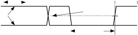
The width of the SE0 in the EOP is approximately 2 * TPERIOD. The SE0 width is measured with the same load used for maximum rise and fall times and is measured at the same level as the differential signal crossover points of the data lines (see Figure 7-27).
127
|
|
|
|
Universal Serial Bus Specification Revision 1.1 |
|||||||||||
TPERIOD |
|
|
|
|
|
|
|
|
|
|
|
|
|
|
|
|
|
|
|
|
|
|
|
|
|
|
|
|
|
||
|
|
|
|
|
|
|
|
|
|
|
|
|
|
||
|
|
|
|
|
|
|
|
|
|
|
|
|
|
|
|
|
|
|
|
|
|
|
|
|
|
|
|
|
|
||
Differential |
|
|
|
|
|
|
|
|
|
|
Data |
|
|||
|
|
|
|
|
|
|
|
|
|
Crossover |
|
||||
Data Lines |
|
|
|
|
|
|
|
|
|
|
Level |
|
|||
|
|
|
|
|
|
|
|
|
|
||||||
|
|
|
|
|
|
|
|
|
|
|
|
|
|
|
|
|
|
|
|
|
|
|
|
|
|
|
|
|
|
|
|
|
|
|
|
|
|
|
|
|
|
|
|
|
SE0 for |
||
|
|
|
|
|
|
|
|
|
|
|
|
|
EOP |
||
|
|
|
|
|
|
|
|
|
|
|
|
|
|||
|
|
|
|
|
|
|
|
|
|
|
|
|
Width |
||
Figure 7-27. SE0 for EOP Width Timing
For full-speed transmissions, the SE0 for EOP width from the transmitter must be between 160ns and 175ns.
For low-speed transmissions, the transmitter’s SE0 for EOP width must be between 1.25 s and 1.50 s.
These ranges include timing variations due to differential buffer delay and rise and fall time mismatches and to noise and other random effects.
A receiver must accept any valid EOP. Receiver design should note that the single-ended input threshold voltage can be different from the differential crossover voltage and the SE0 transitions will in general be asynchronous to the clock encoded in the NRZI stream.
A full-speed EOP may have the SE0 interval reduced to as little as 82ns (TFEOPR) and a low-speed SE0 interval may be as short as 670ns (TLEOPR).
A hub may tear down connectivity if it sees an SE0 of at least TFST or TLST followed by a transition to the J state. A hub must tear down connectivity on any valid EOP.
7.1.14 Hub Signaling Timings
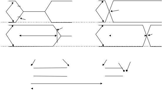
The propagation of a full-speed, differential data signal through a hub is shown in Figure 7-28. The downstream signaling is measured without a cable connected to the port and with the load used for measuring rise and fall times. The total delay through the upstream cable and hub electronics must be a maximum of 70ns (THDD1). If the hub has a USB detachable cable, then the delay (THDD2) through hub electronics and the associated transmission line must be a maximum of 44ns to allow for a worst-case cable delay of 26ns (TFSCBL). The delay through this hub is measured in both the upstream and downstream directions, as shown in Figure 7-28B, from data line crossover at the input port to data line crossover at the output port.
128
Universal Serial Bus Specification Revision 1.1
Upstream End |
|
|
|
|
|
|
|
|
|
|
|
|
|
|
|
|
|
|
|
|
|
|
|
|
|
|
|
|
|
Data Line |
|
||||||
|
|
|
|
|
|
|
|
|
|
|
|
|
|
|
|
|
|
|
|
|
|
|
|
|
|
|
|
|
|
||||||||
|
|
|
|
|
|
|
|
|
|
|
|
|
|
|
|
|
|
|
|
|
Downstream |
|
|
|
|
|
|
Crossover |
|
||||||||
of Cable |
|
|
|
|
|
|
|
|
|
|
|
|
|
|
|
|
|
|
|
|
|
|
|
|
|
|
|
|
|||||||||
|
|
|
|
|
|
|
|
|
|
|
|
|
|
|
|
|
|
|
|
|
Port |
|
|
|
|
|
|
|
|
Point |
|
||||||
|
|
|
|
|
|
|
|
|
|
|
|
|
|
|
|
|
|
|
|
|
|
|
|
|
|
|
|
|
|
|
|
|
|
|
|
|
|
|
|
|
|
|
50% Point of |
|
|
|
|
|
|
|
|
|
|
|
|
|
|
|
|
|
|
|
|
|
|
|
|
|
|
|
|
|
|||
VSS |
|
|
|
|
Initial Swing |
|
|
|
|
|
|
|
|
|
|
|
|
|
|
|
|
|
|
|
|
|
|
|
|
|
|
|
|
|
|||
|
|
|
|
|
|
|
|
|
|
|
|
50% Point of |
|
|
|
|
|
|
|
|
|
|
|
|
|
|
|
|
|
|
|
|
|
||||
|
|
|
|
|
|
|
|
|
|
|
|
|
|
|
|
|
|
|
|
|
|
|
|
|
|
|
|
|
|
|
|
|
|
||||
|
|
|
|
|
|
|
|
|
|
|
|
|
Initial Swing |
|
|
|
|
|
|
|
|
|
|
|
|
|
|
|
|
|
|
|
|
Data Line |
|||
|
|
|
|
|
|
|
|
|
|
|
|
|
|
|
|
|
|
|
|
|
|
|
|
|
|
|
|
|
|
|
|
|
|
|
|
|
|
Downstream |
|
|
|
|
|
Hub Delay |
|
|
|
|
|
|
|
|
|
|
|
Upstream End |
|
|
|
|
|
|
|
|
Hub Delay |
|
|
||||||||
|
|
|
|
|
|
|
|
|
|
|
|
|
|
|
|
|
|
|
|
|
|
|
|
|
|
Crossover |
|||||||||||
Port |
|
|
|
|
|
Downstream |
|
|
|
|
|
|
|
|
|
|
|
|
|
of Cable |
|
|
|
|
|
|
|
|
|
Upstream |
|
Point |
|||||
|
|
|
|
|
|
70ns (max) |
|
|
|
|
|
|
|
|
|
|
|
|
|
|
|
|
|
|
|
|
|
|
70ns (max) |
|
|
||||||
|
|
|
|
|
|
|
|
|
|
|
|
|
|
|
|
|
|
|
|
|
|
|
|
|
|
|
|
|
|
||||||||
|
|
|
|
|
|
|
|
|
|
|
|
|
|
|
|
|
|
|
|
|
|
|
|
|
|
|
|
|
|
|
|
||||||
VSS |
|
|
|
|
|
|
|
|
|
|
|
|
|
|
|
|
|
|
|
|
|
|
|
|
|
|
|
|
|
|
|
|
|
|
|
|
|
|
|
|
|
|
|
|
|
|
|
|
|
|
|
|
|
|
|
|
|
|
|
|
|
|
|
|
|
|
|
|
|
|
|
|
|
|
|
|
|
|
|
|
|
|
|
|
|
|
|
|
|
|
|
|
|
|
|
|
|
|
|
|
|
|
|
|
|
|
|
|
|
|
|
|
|
|
A. Downstream Hub Delay |
|
|
|
|
|
|
B. Upstream Hub Delay |
|
||||||||||||||||||||||||||||
|
|
|
|
|
|||||||||||||||||||||||||||||||||
|
|
upstream end of cable |
|
upstream port |
downstream port |
plug |
|
|
receptacle |
|
|||||||||||||||||||||||||||
|
|
|
|
|
|
|
|
|
|
|
|
|
|
|
|
|
|
|
|
|
|
|
|
|
|
|
|
|
|
|
|
||||||
|
|
|
|
|
|
|
|
|
|
|
|
|
|
|
|
|
|
|
|
|
|
|
|
|
|
|
|
|
|
|
|
|
|
|
|
||
|
|
|
|
|
|
|
|
|
|
|
|
|
|
|
|
|
|
|
|
|
|
|
|
|
|
|
|
|
|
|
|
|
|
|
|
|
|
|
|
Host or |
|
|
|
|
|
|
|
|
|
|
|
|
|
|
|
|
|
|
Hub |
|
|
|
|
|
|
|
|
|
|
|
Function |
|
|||
|
|
|
|
|
|
|
|
|
|
|
|
|
|
|
|
|
|
|
|
|
|
|
|
|
|
|
|
|
|
|
|
||||||
|
|
Hub |
|
|
|
|
|
|
|
|
|
|
|
|
|
|
|
|
|
|
|
|
|
|
|
|
|
|
|
|
|
|
|||||
|
|
|
|
|
|
|
|
|
|
|
|
|
|
|
|
|
|
|
|
|
|
|
|
|
|
|
|
|
|
|
|
|
|
|
|
||
|
|
|
|
|
|
|
|
|
|
|
|
|
|
|
|
|
|
|
|
|
|
|
|
|
|
|
|
|
|
|
|
||||||
|
|
|
|
|
|
|
|
|
|
|
|
|
|
|
|
|
|
|
|
|
|
|
|
|
|
|
|
|
|
|
|
|
|
|
|
|
|
|
|
|
|
|
|
|
|
|
|
|
|
|
|
|
|
|
|
|
|
|
|
|
|
|
|
|
|||||||||||
|
|
|
|
|
|
|
|
|
|
downstream signaling |
|
|
|
|
|
|
|
|
|
|
|
|
|
|
|
|
|||||||||||
|
|
|
|
|
|
|
|
|
|
|
|
|
|
|
|
|
|
|
|
|
|
|
|
|
|
|
|
|
|
|
|
|
|
|
|
|
|
|
|
|
|
|
|
|
|
|
|
|
upstream signaling |
|
|
|
|
|
|
|
|
|
|
|
|
|
|
|
|
|
|||||||||
|
|
|
|
|
|
|
|
|
|
|
|
|
|
|
|
|
|
|
|
|
|
|
|
|
|
|
|
||||||||||
|
|
|
|
|
|
|
|
|
|
|
|
|
|
|
|
|
|
|
|
|
|
|
|
|
|
|
|
|
|
|
|
|
|
|
|
|
|
|
|
|
|
|
|
|
|
|
|
|
|
|
|
|
|
|
|
|
|
|
|
|
|
|
|
|
|
|
|
|
|
|
|
|
|
|
|
C. Measurement Points
Figure 7-28. Hub Propagation Delay of Full-speed Differential Signals
Low-speed propagation delay for differential signals is measured in the same fashion as for full-speed signaling. The maximum low-speed hub delay is 300ns (TLHDD). This allows for the slower low-speed buffer propagation delay and rise and fall times. It also provides time for the hub to re-clock the low-speed data in the upstream direction.
When the hub acts as a repeater, it must reproduce the received, full-speed signal accurately on its outputs. This means that for differential signals, the propagation delays of a J-to-K state transition must match closely to the delays of a K-to-J state transition. For full-speed propagation, the maximum difference allowed between these two delays (THDJ1) (see Figure 7-28 and Figure 7-42) for a hub plus cable is 3.0ns. Similarly, the difference in delay between any two J-to-K or K-to-J transitions through a hub (THDJ2) must be less than 1.0ns. For low-speed propagation in the downstream direction, the corresponding allowable jitter (TLDHJ1) is 45ns and (TLDHJ2) 15ns, respectively. For low-speed propagation in the upstream direction, the allowable jitter is 45ns in both cases (TLUHJ1 and TLUHJ2).
An exception to this case is the skew that can be introduced in the Idle-to-K state transition at SOP (TFSOP and TLSOP) (refer to Section 7.1.7.2). In this case, the delay to the opposite port includes the time to enable the output buffer. However, the delays should be closely matched to the normal hub delay and the maximum additional delay difference over a normal J-to-K transition is 5.0ns. This limits the maximum distortion of the first bit in the packet.
Note: because of this distortion of the SOP transition relative to the next K-to-J state transition, the first SYNC field bit should not be used to synchronize the receiver to the data stream.
The EOP must be propagated through a hub in the same way as the differential signaling. The propagation delay for sensing an SE0 must be no less than the greater of the J-to-K, or K-to-J differential data delay (to avoid truncating the last data bit in a packet), but not more than 15ns greater than the larger of these differential delays at full-speed and 200ns at low-speed (to prevent creating a bit stuff error at the end of the packet). EOP delays are shown in Figure 7-43.
Because the sense levels for the SE0 state are not at the midpoint of the signal swing, the width of SE0 state will be changed as it passes through each hub. A hub may not change the width of the SE0 state in a
129
Universal Serial Bus Specification Revision 1.1
full-speed EOP by more than 15ns (TFHESK), as measured by the difference of the leading edge and trailing edge delays of the SE0 state (see Figure 7-43). An SE0 from a low-speed device has long rise and fall times and is subject to greater skew, but this conditions exists only on the cable from the low-speed device to the port to which it is connected. Thereafter, the signaling uses full-speed buffers and their faster rise and fall times. The SE0 from the low-speed device cannot be changed by more than 300ns (TLHESK) as it passes through the hub to which the device is connected. This time allows for some signal conditioning in the low-speed port to reduce its sensitivity to noise.
7.1.15 Receiver Data Jitter
The data receivers for all types of devices must be able to properly decode the differential data in the presence of jitter. The more of the bit cell that any data edge can occupy and still be decoded, the more reliable the data transfer will be. Data receivers are required to decode differential data transitions that occur in a window plus and minus a nominal quarter bit cell from the nominal (centered) data edge position. (A simple 4X over-sampling state machine DPLL can be built that satisfies these requirements.) This requirement is derived in Table 7-2 and Table 7-3. The tables assume a worst-case topology of five hubs between the host and device and the worst-case number of seven bits between transitions. The derived numbers are rounded up for ease of specification.
Jitter will be caused by the delay mismatches discussed above and by mismatches in the source and destination data rates (frequencies). The receive data jitter budgets for fulland low-speed are given in Table 7-2 and Table 7-3. These tables give the value and totals for each source of jitter for both consecutive (next) and paired transitions. Note that the jitter component related to the source or destination frequency tolerance has been allocated to the appropriate device (i.e., the source jitter includes bit shifts due to source frequency inaccuracy over the worst-case data transition interval). The output driver jitter can be traded off against the device clock accuracy in a particular implementation as long as the jitter specification is met.
The low-speed jitter budget table has an additional line in it because the jitter introduced by the hub to which the low-speed device is attached is different from all the other devices in the data path. The remaining devices operate with full-speed signaling conventions (though at low-speed data rate).
130
Universal Serial Bus Specification Revision 1.1
Table 7-2. Full-speed Jitter Budget
Jitter Source |
|
Full-speed |
|
|
|
|
|
|
|
|
Next Transition |
Paired Transition |
||
|
|
|
|
|
|
Each (ns) |
Total (ns) |
Each (ns) |
Total (ns) |
|
|
|
|
|
Source Driver Jitter |
2.0 |
2.0 |
1.0 |
1.0 |
Source Frequency Tolerance (worst-case) |
0.21/bit |
1.5 |
0.21/bit |
3.0 |
|
|
|
|
|
Source Jitter Total |
|
3.5 |
|
4.0 |
Hub Jitter |
3.0 |
15.0 |
1.0 |
5.0 |
|
|
|
|
|
Jitter Specification |
|
18.5 |
|
9.0 |
Destination Frequency Tolerance |
0.21/bit |
1.5 |
0.21/bit |
3.0 |
|
|
|
|
|
Receiver Jitter Budget |
|
20.0 |
|
12.0 |
|
|
|
|
|
Table 7-3. Low-speed Jitter Budget
Jitter Source |
|
Low-speed Upstream |
||
|
|
|
|
|
|
Next Transition |
Paired Transition |
||
|
|
|
|
|
|
Each (ns) |
Total (ns) |
Each (ns) |
Total (ns) |
|
|
|
|
|
Function Driver Jitter |
25.0 |
25.0 |
10.0 |
10.0 |
Function Frequency Tolerance (worst-case) |
10.0/bit |
70.0 |
10.0/bit |
140.0 |
|
|
|
|
|
Source (Function) Jitter Total |
|
95.0 |
|
150.0 |
Hub with Low-speed Device Jitter |
45.0 |
45.0 |
45.0 |
45.0 |
Remaining (full-speed) Hubs' Jitter |
3.0 |
12.0 |
1.0 |
4.0 |
|
|
|
|
|
Jitter Specification |
|
152.0 |
|
199.0 |
Host Frequency Tolerance |
1.7/bit |
12.0 |
1.7/bit |
24.0 |
|
|
|
|
|
Host Receiver Jitter Budget |
|
164.0 |
|
223.0 |
|
|
|
|
|
|
|
Low-speed Downstream |
||
|
|
|
|
|
|
Next Transition |
Paired Transition |
||
|
|
|
|
|
|
Each (ns) |
Total (ns) |
Each (ns) |
Total (ns) |
|
|
|
|
|
Host Driver Jitter |
2.0 |
2.0 |
1.0 |
1.0 |
Host Frequency Tolerance (worst-case) |
1.7/bit |
12.0 |
1.7/bit |
24.0 |
|
|
|
|
|
Source (Host) Jitter Total |
|
14.0 |
|
25.0 |
Hub with Low-speed Device Jitter |
45.0 |
45.0 |
15.0 |
15.0 |
Remaining (full-speed) Hubs' Jitter |
3.0 |
12.0 |
1.0 |
4.0 |
|
|
|
|
|
Jitter Spec |
|
71.0 |
|
44.0 |
Function Frequency Tolerance |
10.0/bit |
70.0 |
10.0/bit |
140.0 |
|
|
|
|
|
Function Receiver Jitter Budget |
|
141.0 |
|
184.0 |
|
|
|
|
|
Note: this table describes the host transmitting at low-speed data rate using full-speed signaling to a low-speed device through the maximum number of hubs. When the host is directly connected to the low-speed device, then it uses low-speed data rate and low-speed signaling, and the host has to meet the source jitter listed in the “Jitter Specification” row.
131