

Universal Serial Bus Specification Revision 1.1
Full-speed Captive Cables must meet the following electrical requirements:
The cable must be terminated on one end with an overmolded Series “A” plug and the opposite end is vendor specific. If the vendor specific interconnect is to be hot plugged it must meet the same performance requirements as the USB “B” connector.
The cable must be rated for Full-speed.
The cable impedance must match the impedance of the Full-speed drivers. The drivers are characterized to drive specific cable impedance. Refer to Section 7.1.1 for details.
The maximum cable length is determined by the attenuation of the signal pair. Refer to Section 7.1.17 for details.
The maximum cable length is determined by the propagation delay though the cable. The USB utilizes an unterminated transmission scheme, exceeding this limit will cause signaling reflections to interfere with data transmission. Refer to Section 7.1.14 for details.
Differences in propagation delay between the two signal conductors must be minimized. Refer to Section 7.1.3 for details.
The GND lead provides a common reference between the upstream and downstream ports. The maximum cable length is determined by the voltage drop across the GND lead. Refer to Section 7.2.2 for details. The minimum wire gauge is calculated using the worst case current consumption.
The VBUS lead provides power to the connected device. The minimum wire gauge is vendor specific.
6.4.3 Low-speed Captive Cable Assemblies
Assemblies are considered captive if they are provided with a vendor-specific disconnect means. Lowspeed cable may only be used on Low-speed devices.
Figure 6-4 illustrates a Low-speed cable assembly.
78

Universal Serial Bus Specification Revision 1.1
8 |
7 |
6 |
5 |
4 |
3 |
2 |
1 |
|
|
|
|
|
|
|
|
IMPORTANT NOTICE: For use in Low Speed applications only.
H |
H |
|
A |
B |
|
G |
A |
B |
G |
|
|
Overmolded Series "A" Plug
(Always upstream towards the "host" system.)
F |
Detail A - A |
|
|
|
|
|
|
|
|
F |
|||
|
|
|
|
|
|
|
|
|
|
||||
|
(Series "A" Plug) |
|
|
|
|
|
|
|
|
||||
|
|
15.7 |
|
|
|
|
|
|
|
Cut End |
|
||
|
|
7.5 |
|
|
(Always downstream |
towards the USB Device.) |
|
||||||
|
|
|
|
|
|
|
|||||||
E |
1 |
2 |
3 |
4 |
|
|
|
|
|
|
|
|
E |
|
|
|
|
|
Detail B - B (Typical Terminations) |
|
|||||||
|
|
|
|
|
|
|
|
||||||
|
|
|
|
12.0 |
Blunt Cut Termination |
|
Prepared Termination |
|
|||||
|
|
|
|
|
|
|
|
|
|
|
|
|
|
|
|
|
|
|
|
Polyvinyl Chloride (PVC) |
|
Polyvinyl Chloride (PVC) Jacket |
|
||||
|
|
|
|
|
|
Jacket |
Blunt Cut Termination |
|
|
|
Red (VB U S) |
|
|
|
|
|
|
|
|
|
|
|
|
|
|
||
|
|
|
|
|
|
|
|
|
|
Black (Ground) |
|
||
D |
|
|
|
|
|
|
(Length Dimension Point) |
|
|
|
D |
||
|
|
|
|
27.0 |
|
|
|
|
|
|
Green (D +) |
|
|
|
|
|
|
|
|
|
|
|
|
|
|
||
|
|
|
|
|
|
|
|
|
|
|
White (D -) |
|
|
|
|
|
|
|
|
|
|
|
|
|
User Specified |
|
|
C |
|
|
|
|
|
|
|
|
|
|
Length Dimension Point |
C |
|
|
|
|
9.0 |
|
|
|
|
|
|
|
|
||
|
|
|
|
|
|
|
|
|
|
|
|
|
|
|
|
|
|
Optional Molded |
|
|
|
|
|
|
|
|
|
|
|
|
|
Strain Relief |
|
|
|
|
|
|
|
|
|
B |
|
|
|
|
|
|
|
|
|
|
|
|
B |
|
All dimensions are in millimeters (m m ) |
|
|
|
|
|
|
|
|||||
|
unless otherwise noted. |
|
|
|
|
|
|
|
|
||||
|
D i m e n s i o n s a r e |
T Y P I C A L an d ar e for |
|
|
Series "A" Plug to Cut End |
|
|||||||
|
general reference purposes only. |
|
|
|
USB Low Speed |
|
|
||||||
A |
|
|
|
|
|
|
|
Hardwired Cable Assembly A |
|||||
|
|
|
|
|
|
|
|
SIZE |
|
DATE |
DRAWING NUMBER |
REV |
|
|
|
|
|
|
|
|
|
A |
|
2/98 |
N/A |
C |
|
|
|
|
|
|
|
|
|
SCALE: |
N/A |
SHEET |
1 of 1 |
|
|
|
8 |
|
|
7 |
6 |
5 |
4 |
3 |
|
|
2 |
1 |
|
Figure 6-4. USB Low-speed Hardwired Cable Assembly
79
Universal Serial Bus Specification Revision 1.1
Low-speed Captive Cables must meet the following electrical requirements:
The cable must be terminated on one end with an overmolded Series “A” plug and the opposite end is vendor specific. If the vendor specific interconnect is to be hot plugged it must meet the same performance requirements as the USB “B” connector.
Low-Speed drivers are characterized for operation over a range of capacitive loads. This value includes all sources of capacitance on the D+ and D-lines, not just the cable. Cable selection must insure that total load capacitance falls between specified minimum and maximum values. If the desired implementation does not meet the minimum requirement, additional capacitance needs to be added to the device. Refer to section 7.1.1.2 for details.
The maximum Low-speed cable length determined by the rise and fall times of Low-speed signaling. This forces Low-speed cable to be significantly shorter then Full-speed. Refer to Section 7.1.1.2 for details.
Differences in propagation delay between the two signal conductors must be minimized. Refer to Section 7.1.3 for details.
The GND lead provides a common reference between the upstream and downstream ports. The maximum cable length is determined by the voltage drop across the GND lead. Refer to Section 7.2.2 for details. The minimum wire gauge is calculated using the worst case current consumption.
The VBUS lead provides power to the connected device. The minimum wire gauge is vendor specific.
6.4.4 Prohibited Cable Assemblies
USB is optimized for ease of use. The expectation it that if the device can be plugged in it will work. By specification, the only conditions that prevent a USB device from being successfully utilized are lack of power, lack of bandwidth, and excessive topology depth. These conditions are well understood by the system software.
Non-acceptable cables may work in some situations but they cannot be guaranteed to work in all instances.
Extension cable
Cables that provide a Series “A” plug with a series “A” receptacle or a Series “B” plug with a Series “B” receptacle. This allows multiple cable segments to be connected together, possibly exceeding the maximum permissible cable length.
Cable assembly that violates USB topology rules
A cable with both ends terminated in either Series “A” plugs or Series “B” receptacles. This cable allows two downstream ports to be directly connected.
Note: This prohibition does not prevent using a USB device to provide a bridge between two USB busses.
Low-speed detachable cable
Detachable cables must be Full-speed. Low-speed devices are prohibited from using detachable cables. Detachable cable is Full-speed rated, using a long Full-speed cable exceeds the capacitive load of Low-speed.
6.5Connector Mechanica l Configuration and Material Requirements
The USB Icon is used to identify USB plugs and the receptacles. Figure 6-5 illustrates the USB Icon
80
Universal Serial Bus Specification Revision 1.1
|
|
All dimensions are ± 5% |
||
|
|
|
L |
|
|
|
Dia:1.33 L |
0.33 L |
|
|
Dia:1.67 L |
|
|
|
|
|
Dia:L |
|
L |
1.50 L |
|
|
Dia:L |
0.33 L |
|
|
|
|
L |
|
|
|
|
0.5 L |
1.50 L |
|
Dia:L |
Dia:L |
L |
|
|
|
|
|
|
|
|
|
L |
|
|
Dia:1.33 L |
L |
|
|
1.67 L |
|
0.33 L |
|
|
2.33 L |
|
|
|
|
3.75 L |
|
|
|
|
5.00 L |
|
|
|
|
5.17 L |
|
|
|
|
6.25 L |
|
|
|
|
8.00 L |
|
|
|
Figure 6-5. USB Icon
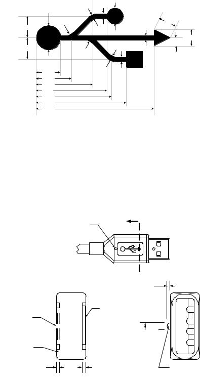
6.5.1 USB Icon Location
The USB Icon is embossed, in a recessed area, on the topside of the USB plug. This provides easy user recognition and facilitates alignment during the mating process. The USB Icon and Manufacture’s logo should not project beyond the overmold surface. The USB Icon is required, while the Manufacture’s logo is recommended, for both Series “A” and “B” plug assemblies. The USB Icon is also located adjacent to each receptacle. Receptacles should be oriented to allow the Icon on the plug to be visible during the mating process. Figure 6-6 illustrates the typical plug orientation.
Top View
A
Optional Top
"Locator Detail"
|
A Locator |
|
|
|
Height |
|
|
|
Approximately |
|
|
|
0.6mm |
|
|
|
(0.024") |
|
|
|
Manufacturer's |
1 |
|
Engraved USB |
Engraved Logo |
2 |
|
|
|||
Icon |
|
||
|
|
||
|
Locator Width |
3 |
|
|
|
||
|
Approximately |
4 |
|
|
0.5mm |
||
Overmolding |
|
||
(0.020") |
|
||
|
|
||
0.6mm (0.024") |
0.6mm (0.024") Max |
|
|
Max |
Manufacturer's |
Optional Top |
|
USB Icon |
Logo |
||
"Locator Detail" |
|||
Engraving Recess |
Engraving Recess |
Section A - A
(Plug Cross-Section)
Figure 6-6. Typical USB Plug Orientation
81