

- •Chapter 1
- •1.1 Motivation
- •1.2 Objective of the Specification
- •1.3 Scope of the Document
- •1.4 Document Organization
- •Chapter 2
- •Chapter 3
- •3.1 Goals for the Universal Serial Bus
- •3.2 Taxonomy of Application Space
- •3.3 Feature List
- •Chapter 4
- •4.1 USB System Description
- •4.1.1 Bus Topology
- •4.2 Physical Interface
- •4.2.1 Electrical
- •4.2.2 Mechanical
- •4.3 Power
- •4.3.1 Power Distribution
- •4.3.2 Power Management
- •4.4 Bus Protocol
- •4.5 Robustness
- •4.5.1 Error Detection
- •4.5.2 Error Handling
- •4.6 System Configuration
- •4.6.1 Attachment of USB Devices
- •4.6.2 Removal of USB Devices
- •4.6.3 Bus Enumeration
- •4.7 Data Flow Types
- •4.7.1 Control Transfers
- •4.7.2 Bulk Transfers
- •4.7.3 Interrupt Transfers
- •4.7.4 Isochronous Transfers
- •4.7.5 Allocating USB Bandwidth
- •4.8 USB Devices
- •4.8.1 Device Characterizations
- •4.8.2 Device Descriptions
- •4.9 USB Host: Hardware and Software
- •4.10 Architectural Extensions
- •Chapter 5
- •5.1 Implementer Viewpoints
- •5.2 Bus Topology
- •5.2.1 USB Host
- •5.2.2 USB Devices
- •5.2.3 Physical Bus Topology
- •5.2.4 Logical Bus Topology
- •5.2.5 Client Software-to-function Relationship
- •5.3 USB Communication Flow
- •5.3.1 Device Endpoints
- •5.3.2 Pipes
- •5.4 Transfer Types
- •5.5 Control Transfers
- •5.5.1 Control Transfer Data Format
- •5.5.2 Control Transfer Direction
- •5.5.3 Control Transfer Packet Size Constraints
- •5.5.4 Control Transfer Bus Access Constraints
- •5.5.5 Control Transfer Data Sequences
- •5.6 Isochronous Transfers
- •5.6.1 Isochronous Transfer Data Format
- •5.6.2 Isochronous Transfer Direction
- •5.6.3 Isochronous Transfer Packet Size Constraints
- •5.6.4 Isochronous Transfer Bus Access Constraints
- •5.6.5 Isochronous Transfer Data Sequences
- •5.7 Interrupt Transfers
- •5.7.1 Interrupt Transfer Data Format
- •5.7.2 Interrupt Transfer Direction
- •5.7.3 Interrupt Transfer Packet Size Constraints
- •5.7.4 Interrupt Transfer Bus Access Constraints
- •5.7.5 Interrupt Transfer Data Sequences
- •5.8 Bulk Transfers
- •5.8.1 Bulk Transfer Data Format
- •5.8.2 Bulk Transfer Direction
- •5.8.3 Bulk Transfer Packet Size Constraints
- •5.8.4 Bulk Transfer Bus Access Constraints
- •5.8.5 Bulk Transfer Data Sequences
- •5.9 Bus Access for Transfers
- •5.9.1 Transfer Management
- •5.9.2 Transaction Tracking
- •5.9.3 Calculating Bus Transaction Times
- •5.9.4 Calculating Buffer Sizes in Functions and Software
- •5.9.5 Bus Bandwidth Reclamation
- •5.10 Special Considerations for Isochronous Transfers
- •5.10.1 Example Non-USB Isochronous Application
- •5.10.2 USB Clock Model
- •5.10.3 Clock Synchronization
- •5.10.4 Isochronous Devices
- •5.10.5 Data Prebuffering
- •5.10.6 SOF Tracking
- •5.10.7 Error Handling
- •5.10.8 Buffering for Rate Matching
- •Chapter 6
- •6.1 Architectural Overview
- •6.3 Cable
- •6.4 Cable Assembly
- •6.4.1 Detachable Cable Assemblies
- •6.4.3 Low-speed Captive Cable Assemblies
- •6.4.4 Prohibited Cable Assemblies
- •6.5.1 USB Icon Location
- •6.5.2 USB Connector Termination Data
- •6.5.3 Series “A” and Series “B” Receptacles
- •6.5.4 Series “A” and Series “B” Plugs
- •6.6.1 Description
- •6.6.2 Construction
- •6.6.3 Electrical Characteristics
- •6.6.4 Cable Environmental Characteristics
- •6.6.5 Listing
- •6.7 Electrical, Mechanical and Environmental Compliance Standards
- •6.7.1 Applicable Documents
- •6.8 USB Grounding
- •Chapter 7
- •7.1 Signaling
- •7.1.1 USB Driver Characteristics
- •7.1.2 Data Signal Rise and Fall
- •7.1.3 Cable Skew
- •7.1.4 Receiver Characteristics
- •7.1.5 Device Speed Identification
- •7.1.6 Input Characteristics
- •7.1.7 Signaling Levels
- •7.1.8 Data Encoding/Decoding
- •7.1.9 Bit Stuffing
- •7.1.10 Sync Pattern
- •7.1.11 Data Signaling Rate
- •7.1.12 Frame Interval and Frame Interval Adjustment
- •7.1.13 Data Source Signaling
- •7.1.14 Hub Signaling Timings
- •7.1.15 Receiver Data Jitter
- •7.1.16 Cable Delay
- •7.1.17 Cable Attenuation
- •7.1.18 Bus Turn-around Time and Inter-packet Delay
- •7.1.19 Maximum End-to-end Signal Delay
- •7.2 Power Distribution
- •7.2.1 Classes of Devices
- •7.2.2 Voltage Drop Budget
- •7.2.3 Power Control During Suspend/Resume
- •7.2.4 Dynamic Attach and Detach
- •7.3 Physical Layer
- •7.3.1 Regulatory Requirements
- •7.3.2 Bus Timing/Electrical Characteristics
- •7.3.3 Timing Waveforms
- •Chapter 8
- •8.1 Bit Ordering
- •8.2 SYNC Field
- •8.3 Packet Field Formats
- •8.3.1 Packet Identifier Field
- •8.3.2 Address Fields
- •8.3.3 Frame Number Field
- •8.3.4 Data Field
- •8.3.5 Cyclic Redundancy Checks
- •8.4 Packet Formats
- •8.4.1 Token Packets
- •8.4.2 Start-of-Frame Packets
- •8.4.3 Data Packets
- •8.4.4 Handshake Packets
- •8.4.5 Handshake Responses
- •8.5 Transaction Formats
- •8.5.1 Bulk Transactions
- •8.5.2 Control Transfers
- •8.5.3 Interrupt Transactions
- •8.5.4 Isochronous Transactions
- •8.6 Data Toggle Synchronization and Retry
- •8.6.1 Initialization via SETUP Token
- •8.6.2 Successful Data Transactions
- •8.6.3 Data Corrupted or Not Accepted
- •8.6.4 Corrupted ACK Handshake
- •8.6.5 Low-speed Transactions
- •8.7 Error Detection and Recovery
- •8.7.1 Packet Error Categories
- •8.7.2 Bus Turn-around Timing
- •8.7.3 False EOPs
- •8.7.4 Babble and Loss of Activity Recovery
- •Chapter 9
- •9.1 USB Device States
- •9.1.1 Visible Device States
- •9.1.2 Bus Enumeration
- •9.2 Generic USB Device Operations
- •9.2.1 Dynamic Attachment and Removal
- •9.2.2 Address Assignment
- •9.2.3 Configuration
- •9.2.4 Data Transfer
- •9.2.5 Power Management
- •9.2.6 Request Processing
- •9.2.7 Request Error
- •9.3 USB Device Requests
- •9.3.1 bmRequestType
- •9.3.2 bRequest
- •9.3.3 wValue
- •9.3.4 wIndex
- •9.3.5 wLength
- •9.4 Standard Device Requests
- •9.4.1 Clear Feature
- •9.4.2 Get Configuration
- •9.4.3 Get Descriptor
- •9.4.4 Get Interface
- •9.4.5 Get Status
- •9.4.6 Set Address
- •9.4.7 Set Configuration
- •9.4.8 Set Descriptor
- •9.4.9 Set Feature
- •9.4.10 Set Interface
- •9.4.11 Synch Frame
- •9.5 Descriptors
- •9.6 Standard USB Descriptor Definitions
- •9.6.1 Device
- •9.6.2 Configuration
- •9.6.3 Interface
- •9.6.4 Endpoint
- •9.6.5 String
- •9.7 Device Class Definitions
- •9.7.1 Descriptors
- •9.7.2 Interface(s) and Endpoint Usage
- •9.7.3 Requests
- •Chapter 10
- •10.1 Overview of the USB Host
- •10.1.1 Overview
- •10.1.2 Control Mechanisms
- •10.1.3 Data Flow
- •10.1.4 Collecting Status and Activity Statistics
- •10.1.5 Electrical Interface Considerations
- •10.2 Host Controller Requirements
- •10.2.1 State Handling
- •10.2.2 Serializer/Deserializer
- •10.2.3 Frame Generation
- •10.2.4 Data Processing
- •10.2.5 Protocol Engine
- •10.2.6 Transmission Error Handling
- •10.2.7 Remote Wakeup
- •10.2.8 Root Hub
- •10.2.9 Host System Interface
- •10.3 Overview of Software Mechanisms
- •10.3.1 Device Configuration
- •10.3.2 Resource Management
- •10.3.3 Data Transfers
- •10.3.4 Common Data Definitions
- •10.4 Host Controller Driver
- •10.5 Universal Serial Bus Driver
- •10.5.1 USBD Overview
- •10.5.2 USBD Command Mechanism Requirements
- •10.5.3 USBD Pipe Mechanisms
- •10.5.4 Managing the USB via the USBD Mechanisms
- •10.5.5 Passing USB Preboot Control to the Operating System
- •10.6 Operating System Environment Guides
- •Chapter 11
- •11.1 Overview
- •11.1.1 Hub Architecture
- •11.1.2 Hub Connectivity
- •11.2 Hub Frame Timer
- •11.2.1 Frame Timer Synchronization
- •11.2.2 EOF1 and EOF2 Timing Points
- •11.3 Host Behavior at End-of-Frame
- •11.3.1 Latest Host Packet
- •11.3.2 Packet Nullification
- •11.3.3 Transaction Completion Prediction
- •11.4 Internal Port
- •11.4.1 Inactive
- •11.4.2 Suspend Delay
- •11.4.3 Full Suspend (Fsus)
- •11.4.4 Generate Resume (GResume)
- •11.5 Downstream Ports
- •11.5.1 Downstream Port State Descriptions
- •11.6 Upstream Port
- •11.6.1 Receiver
- •11.6.2 Transmitter
- •11.7 Hub Repeater
- •11.7.1 Wait for Start of Packet from Upstream Port (WFSOPFU)
- •11.7.2 Wait for End of Packet from Upstream Port (WFEOPFU)
- •11.7.3 Wait for Start of Packet (WFSOP)
- •11.7.4 Wait for End of Packet (WFEOP)
- •11.8 Bus State Evaluation
- •11.8.1 Port Error
- •11.8.2 Speed Detection
- •11.8.3 Collision
- •11.9 Suspend and Resume
- •11.10 Hub Reset Behavior
- •11.10.1 Hub Receiving Reset on Upstream Port
- •11.11 Hub Port Power Control
- •11.11.1 Multiple Gangs
- •11.12 Hub I/O Buffer Requirements
- •11.12.1 Pull-up and Pull-down Resistors
- •11.12.2 Edge Rate Control
- •11.13 Hub Controller
- •11.13.1 Endpoint Organization
- •11.13.2 Hub Information Architecture and Operation
- •11.13.3 Port Change Information Processing
- •11.13.4 Hub and Port Status Change Bitmap
- •11.13.5 Over-current Reporting and Recovery
- •11.14 Hub Configuration
- •11.15 Descriptors
- •11.15.1 Standard Descriptors
- •11.15.2 Class-specific Descriptors
- •11.16 Requests
- •11.16.1 Standard Requests
- •11.16.2 Class-specific Requests
- •Index
Universal Serial Bus Specification Revision 1.1
Chapter 9
USB Device Framework
A USB device may be divided into three layers:
The bottom layer is a bus interface that transmits and receives packets.
The middle layer handles routing data between the bus interface and various endpoints on the device. An endpoint is the ultimate consumer or provider of data. It may be thought of as a source or sink for data.
The top layer is the functionality provided by the serial bus device; for instance, a mouse or ISDN interface.
This chapter describes the common attributes and operations of the middle layer of a USB device. These attributes and operations are used by the function-specific portions of the device to communicate through the bus interface and ultimately with the host.
9.1USB Device States
A USB device has several possible states. Some of these states are visible to the USB and the host, while others are internal to the USB device. This section describes those states.
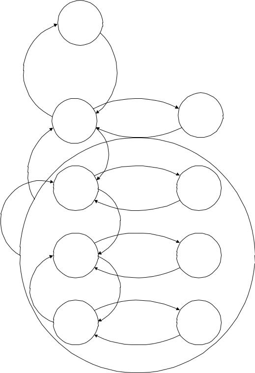
9.1.1 Visible Device States
This section describes USB device states that are externally visible (see Figure 9-1). Table 9-1 summarizes the visible device states.
Note: USB devices perform a reset operation in response to reset signaling on the upstream port. When reset signaling has completed, the USB device is reset.
175
Universal Serial Bus Specification Revision 1.1
Attached
Hub Reset
or |
H u b |
|
Deconfigured Configured |
|
|
|
Bus |
|
|
Inactive |
Suspended |
Powered |
|
|
|
Bus Activity |
|
Power |
Reset |
|
Interruption |
|
|
|
Bus |
|
|
Inactive |
Suspended |
|
Default |
|
Reset |
Bus Activity |
|
|
Address |
|
|
Assigned |
|
|
Bus |
|
|
Inactive |
Suspended |
Address |
||
|
Bus Activity |
|
Device |
Device |
|
Deconfigured Configured |
|
|
|
Bus |
|
|
Inactive |
Suspended |
Configured |
||
Bus Activity
Figure 9-1. Device State Diagram
176
Universal Serial Bus Specification Revision 1.1
Table 9-1. Visible Device States
Attached |
Powered |
Default |
Address |
Configured |
Suspended |
State |
|
|
|
|
|
|
|
No |
-- |
-- |
-- |
-- |
-- |
Device is not attached to |
|
|
|
|
|
|
the USB. Other attributes |
|
|
|
|
|
|
are not significant. |
|
|
|
|
|
|
|
Yes |
No |
-- |
-- |
-- |
-- |
Device is attached to the |
|
|
|
|
|
|
USB, but is not powered. |
|
|
|
|
|
|
Other attributes are not |
|
|
|
|
|
|
significant. |
|
|
|
|
|
|
|
Yes |
Yes |
No |
-- |
-- |
-- |
Device is attached to the |
|
|
|
|
|
|
USB and powered, but |
|
|
|
|
|
|
has not been reset. |
|
|
|
|
|
|
|
Yes |
Yes |
Yes |
No |
-- |
-- |
Device is attached to the |
|
|
|
|
|
|
USB and powered and |
|
|
|
|
|
|
has been reset, but has |
|
|
|
|
|
|
not been assigned a |
|
|
|
|
|
|
unique address. Device |
|
|
|
|
|
|
responds at the default |
|
|
|
|
|
|
address. |
|
|
|
|
|
|
|
Yes |
Yes |
Yes |
Yes |
No |
-- |
Device is attached to the |
|
|
|
|
|
|
USB, powered, has been |
|
|
|
|
|
|
reset, and a unique |
|
|
|
|
|
|
device address has been |
|
|
|
|
|
|
assigned. Device is not |
|
|
|
|
|
|
configured. |
|
|
|
|
|
|
|
Yes |
Yes |
Yes |
Yes |
Yes |
No |
Device is attached to the |
|
|
|
|
|
|
USB, powered, has been |
|
|
|
|
|
|
reset, has a unique |
|
|
|
|
|
|
address, is configured, |
|
|
|
|
|
|
and is not suspended. |
|
|
|
|
|
|
The host may now use |
|
|
|
|
|
|
the function provided by |
|
|
|
|
|
|
the device. |
|
|
|
|
|
|
|
Yes |
Yes |
-- |
-- |
-- |
Yes |
Device is, at minimum, |
|
|
|
|
|
|
attached to the USB and |
|
|
|
|
|
|
is powered and has not |
|
|
|
|
|
|
seen bus activity for 3 ms. |
|
|
|
|
|
|
It may also have a unique |
|
|
|
|
|
|
address and be |
|
|
|
|
|
|
configured for use. |
|
|
|
|
|
|
However, because the |
|
|
|
|
|
|
device is suspended, the |
|
|
|
|
|
|
host may not use the |
|
|
|
|
|
|
device’s function. |
|
|
|
|
|
|
|
177
Universal Serial Bus Specification Revision 1.1
9.1.1.1 Attached
A USB device may be attached or detached from the USB. The state of a USB device when it is detached from the USB is not defined by this specification. This specification only addresses required operations and attributes once the device is attached.
9.1.1.2 Powered
USB devices may obtain power from an external source and/or from the USB through the hub to which they are attached. Externally powered USB devices are termed self-powered. Although self-powered devices may already be powered before they are attached to the USB, they are not considered to be in the Powered state until they are attached to the USB and VBUS is applied to the device.
A device may support both self-powered and bus-powered configurations. Some device configurations support either power source. Other device configurations may be available only if the device is selfpowered. Devices report their power source capability through the configuration descriptor. The current power source is reported as part of a device’s status. Devices may change their power source at any time; e.g., from selfto bus-powered. If a configuration is capable of supporting both power modes, the power maximum reported for that configuration is the maximum the device will draw from VBUS in either mode. The device must observe this maximum, regardless of its mode. If a configuration supports only one power mode and the power source of the device changes, the device will lose its current configuration and address and return to the Powered state. If a device is self-powered and its current configuration requires more than 100mA, then if the device switches to being bus-powered, it must return to the Address state. Self-powered hubs that use VBUS to power the Hub Controller are allowed to remain in the Configured state if local power is lost. Refer to Section 11.14 for details.
A hub port must be powered in order to detect port status changes, including attach and detach. Buspowered hubs do not provide any downstream power until they are configured, at which point they will provide power as allowed by their configuration and power source. A USB device must be able to be addressed within a specified time period from when power is initially applied (refer to Chapter 7). After an attachment to a port has been detected, the host may enable the port, which will also reset the device attached to the port.
9.1.1.3 Default
After the device has been powered, it must not respond to any bus transactions until it has received a reset from the bus. After receiving a reset, the device is then addressable at the default address.
9.1.1.4 Address
All USB devices use the default address when initially powered or after the device has been reset. Each USB device is assigned a unique address by the host after attachment or after reset. A USB device maintains its assigned address while suspended.
A USB device responds to requests on its default pipe whether the device is currently assigned a unique address or is using the default address.
9.1.1.5 Configured
Before a USB device’s function may be used, the device must be configured. From the device’s perspective, configuration involves writing a non-zero value to the device configuration register. Configuring a device or changing an alternate setting causes all of the status and configuration values associated with endpoints in the affected interfaces to be set to their default values. This includes setting the data toggle of any endpoint using data toggles to the value DATA0.
178