

- •Chapter 1
- •1.1 Motivation
- •1.2 Objective of the Specification
- •1.3 Scope of the Document
- •1.4 Document Organization
- •Chapter 2
- •Chapter 3
- •3.1 Goals for the Universal Serial Bus
- •3.2 Taxonomy of Application Space
- •3.3 Feature List
- •Chapter 4
- •4.1 USB System Description
- •4.1.1 Bus Topology
- •4.2 Physical Interface
- •4.2.1 Electrical
- •4.2.2 Mechanical
- •4.3 Power
- •4.3.1 Power Distribution
- •4.3.2 Power Management
- •4.4 Bus Protocol
- •4.5 Robustness
- •4.5.1 Error Detection
- •4.5.2 Error Handling
- •4.6 System Configuration
- •4.6.1 Attachment of USB Devices
- •4.6.2 Removal of USB Devices
- •4.6.3 Bus Enumeration
- •4.7 Data Flow Types
- •4.7.1 Control Transfers
- •4.7.2 Bulk Transfers
- •4.7.3 Interrupt Transfers
- •4.7.4 Isochronous Transfers
- •4.7.5 Allocating USB Bandwidth
- •4.8 USB Devices
- •4.8.1 Device Characterizations
- •4.8.2 Device Descriptions
- •4.9 USB Host: Hardware and Software
- •4.10 Architectural Extensions
- •Chapter 5
- •5.1 Implementer Viewpoints
- •5.2 Bus Topology
- •5.2.1 USB Host
- •5.2.2 USB Devices
- •5.2.3 Physical Bus Topology
- •5.2.4 Logical Bus Topology
- •5.2.5 Client Software-to-function Relationship
- •5.3 USB Communication Flow
- •5.3.1 Device Endpoints
- •5.3.2 Pipes
- •5.4 Transfer Types
- •5.5 Control Transfers
- •5.5.1 Control Transfer Data Format
- •5.5.2 Control Transfer Direction
- •5.5.3 Control Transfer Packet Size Constraints
- •5.5.4 Control Transfer Bus Access Constraints
- •5.5.5 Control Transfer Data Sequences
- •5.6 Isochronous Transfers
- •5.6.1 Isochronous Transfer Data Format
- •5.6.2 Isochronous Transfer Direction
- •5.6.3 Isochronous Transfer Packet Size Constraints
- •5.6.4 Isochronous Transfer Bus Access Constraints
- •5.6.5 Isochronous Transfer Data Sequences
- •5.7 Interrupt Transfers
- •5.7.1 Interrupt Transfer Data Format
- •5.7.2 Interrupt Transfer Direction
- •5.7.3 Interrupt Transfer Packet Size Constraints
- •5.7.4 Interrupt Transfer Bus Access Constraints
- •5.7.5 Interrupt Transfer Data Sequences
- •5.8 Bulk Transfers
- •5.8.1 Bulk Transfer Data Format
- •5.8.2 Bulk Transfer Direction
- •5.8.3 Bulk Transfer Packet Size Constraints
- •5.8.4 Bulk Transfer Bus Access Constraints
- •5.8.5 Bulk Transfer Data Sequences
- •5.9 Bus Access for Transfers
- •5.9.1 Transfer Management
- •5.9.2 Transaction Tracking
- •5.9.3 Calculating Bus Transaction Times
- •5.9.4 Calculating Buffer Sizes in Functions and Software
- •5.9.5 Bus Bandwidth Reclamation
- •5.10 Special Considerations for Isochronous Transfers
- •5.10.1 Example Non-USB Isochronous Application
- •5.10.2 USB Clock Model
- •5.10.3 Clock Synchronization
- •5.10.4 Isochronous Devices
- •5.10.5 Data Prebuffering
- •5.10.6 SOF Tracking
- •5.10.7 Error Handling
- •5.10.8 Buffering for Rate Matching
- •Chapter 6
- •6.1 Architectural Overview
- •6.3 Cable
- •6.4 Cable Assembly
- •6.4.1 Detachable Cable Assemblies
- •6.4.3 Low-speed Captive Cable Assemblies
- •6.4.4 Prohibited Cable Assemblies
- •6.5.1 USB Icon Location
- •6.5.2 USB Connector Termination Data
- •6.5.3 Series “A” and Series “B” Receptacles
- •6.5.4 Series “A” and Series “B” Plugs
- •6.6.1 Description
- •6.6.2 Construction
- •6.6.3 Electrical Characteristics
- •6.6.4 Cable Environmental Characteristics
- •6.6.5 Listing
- •6.7 Electrical, Mechanical and Environmental Compliance Standards
- •6.7.1 Applicable Documents
- •6.8 USB Grounding
- •Chapter 7
- •7.1 Signaling
- •7.1.1 USB Driver Characteristics
- •7.1.2 Data Signal Rise and Fall
- •7.1.3 Cable Skew
- •7.1.4 Receiver Characteristics
- •7.1.5 Device Speed Identification
- •7.1.6 Input Characteristics
- •7.1.7 Signaling Levels
- •7.1.8 Data Encoding/Decoding
- •7.1.9 Bit Stuffing
- •7.1.10 Sync Pattern
- •7.1.11 Data Signaling Rate
- •7.1.12 Frame Interval and Frame Interval Adjustment
- •7.1.13 Data Source Signaling
- •7.1.14 Hub Signaling Timings
- •7.1.15 Receiver Data Jitter
- •7.1.16 Cable Delay
- •7.1.17 Cable Attenuation
- •7.1.18 Bus Turn-around Time and Inter-packet Delay
- •7.1.19 Maximum End-to-end Signal Delay
- •7.2 Power Distribution
- •7.2.1 Classes of Devices
- •7.2.2 Voltage Drop Budget
- •7.2.3 Power Control During Suspend/Resume
- •7.2.4 Dynamic Attach and Detach
- •7.3 Physical Layer
- •7.3.1 Regulatory Requirements
- •7.3.2 Bus Timing/Electrical Characteristics
- •7.3.3 Timing Waveforms
- •Chapter 8
- •8.1 Bit Ordering
- •8.2 SYNC Field
- •8.3 Packet Field Formats
- •8.3.1 Packet Identifier Field
- •8.3.2 Address Fields
- •8.3.3 Frame Number Field
- •8.3.4 Data Field
- •8.3.5 Cyclic Redundancy Checks
- •8.4 Packet Formats
- •8.4.1 Token Packets
- •8.4.2 Start-of-Frame Packets
- •8.4.3 Data Packets
- •8.4.4 Handshake Packets
- •8.4.5 Handshake Responses
- •8.5 Transaction Formats
- •8.5.1 Bulk Transactions
- •8.5.2 Control Transfers
- •8.5.3 Interrupt Transactions
- •8.5.4 Isochronous Transactions
- •8.6 Data Toggle Synchronization and Retry
- •8.6.1 Initialization via SETUP Token
- •8.6.2 Successful Data Transactions
- •8.6.3 Data Corrupted or Not Accepted
- •8.6.4 Corrupted ACK Handshake
- •8.6.5 Low-speed Transactions
- •8.7 Error Detection and Recovery
- •8.7.1 Packet Error Categories
- •8.7.2 Bus Turn-around Timing
- •8.7.3 False EOPs
- •8.7.4 Babble and Loss of Activity Recovery
- •Chapter 9
- •9.1 USB Device States
- •9.1.1 Visible Device States
- •9.1.2 Bus Enumeration
- •9.2 Generic USB Device Operations
- •9.2.1 Dynamic Attachment and Removal
- •9.2.2 Address Assignment
- •9.2.3 Configuration
- •9.2.4 Data Transfer
- •9.2.5 Power Management
- •9.2.6 Request Processing
- •9.2.7 Request Error
- •9.3 USB Device Requests
- •9.3.1 bmRequestType
- •9.3.2 bRequest
- •9.3.3 wValue
- •9.3.4 wIndex
- •9.3.5 wLength
- •9.4 Standard Device Requests
- •9.4.1 Clear Feature
- •9.4.2 Get Configuration
- •9.4.3 Get Descriptor
- •9.4.4 Get Interface
- •9.4.5 Get Status
- •9.4.6 Set Address
- •9.4.7 Set Configuration
- •9.4.8 Set Descriptor
- •9.4.9 Set Feature
- •9.4.10 Set Interface
- •9.4.11 Synch Frame
- •9.5 Descriptors
- •9.6 Standard USB Descriptor Definitions
- •9.6.1 Device
- •9.6.2 Configuration
- •9.6.3 Interface
- •9.6.4 Endpoint
- •9.6.5 String
- •9.7 Device Class Definitions
- •9.7.1 Descriptors
- •9.7.2 Interface(s) and Endpoint Usage
- •9.7.3 Requests
- •Chapter 10
- •10.1 Overview of the USB Host
- •10.1.1 Overview
- •10.1.2 Control Mechanisms
- •10.1.3 Data Flow
- •10.1.4 Collecting Status and Activity Statistics
- •10.1.5 Electrical Interface Considerations
- •10.2 Host Controller Requirements
- •10.2.1 State Handling
- •10.2.2 Serializer/Deserializer
- •10.2.3 Frame Generation
- •10.2.4 Data Processing
- •10.2.5 Protocol Engine
- •10.2.6 Transmission Error Handling
- •10.2.7 Remote Wakeup
- •10.2.8 Root Hub
- •10.2.9 Host System Interface
- •10.3 Overview of Software Mechanisms
- •10.3.1 Device Configuration
- •10.3.2 Resource Management
- •10.3.3 Data Transfers
- •10.3.4 Common Data Definitions
- •10.4 Host Controller Driver
- •10.5 Universal Serial Bus Driver
- •10.5.1 USBD Overview
- •10.5.2 USBD Command Mechanism Requirements
- •10.5.3 USBD Pipe Mechanisms
- •10.5.4 Managing the USB via the USBD Mechanisms
- •10.5.5 Passing USB Preboot Control to the Operating System
- •10.6 Operating System Environment Guides
- •Chapter 11
- •11.1 Overview
- •11.1.1 Hub Architecture
- •11.1.2 Hub Connectivity
- •11.2 Hub Frame Timer
- •11.2.1 Frame Timer Synchronization
- •11.2.2 EOF1 and EOF2 Timing Points
- •11.3 Host Behavior at End-of-Frame
- •11.3.1 Latest Host Packet
- •11.3.2 Packet Nullification
- •11.3.3 Transaction Completion Prediction
- •11.4 Internal Port
- •11.4.1 Inactive
- •11.4.2 Suspend Delay
- •11.4.3 Full Suspend (Fsus)
- •11.4.4 Generate Resume (GResume)
- •11.5 Downstream Ports
- •11.5.1 Downstream Port State Descriptions
- •11.6 Upstream Port
- •11.6.1 Receiver
- •11.6.2 Transmitter
- •11.7 Hub Repeater
- •11.7.1 Wait for Start of Packet from Upstream Port (WFSOPFU)
- •11.7.2 Wait for End of Packet from Upstream Port (WFEOPFU)
- •11.7.3 Wait for Start of Packet (WFSOP)
- •11.7.4 Wait for End of Packet (WFEOP)
- •11.8 Bus State Evaluation
- •11.8.1 Port Error
- •11.8.2 Speed Detection
- •11.8.3 Collision
- •11.9 Suspend and Resume
- •11.10 Hub Reset Behavior
- •11.10.1 Hub Receiving Reset on Upstream Port
- •11.11 Hub Port Power Control
- •11.11.1 Multiple Gangs
- •11.12 Hub I/O Buffer Requirements
- •11.12.1 Pull-up and Pull-down Resistors
- •11.12.2 Edge Rate Control
- •11.13 Hub Controller
- •11.13.1 Endpoint Organization
- •11.13.2 Hub Information Architecture and Operation
- •11.13.3 Port Change Information Processing
- •11.13.4 Hub and Port Status Change Bitmap
- •11.13.5 Over-current Reporting and Recovery
- •11.14 Hub Configuration
- •11.15 Descriptors
- •11.15.1 Standard Descriptors
- •11.15.2 Class-specific Descriptors
- •11.16 Requests
- •11.16.1 Standard Requests
- •11.16.2 Class-specific Requests
- •Index
Universal Serial Bus Specification Revision 1.1
regulator block must implement inrush current limiting. The amount of power that the function block may draw is limited only by the local power supply. Because the local power supply is not required to power any downstream bus ports, it does not need to implement current limiting, soft start, or power switching.
Upstream |
Function Controller |
|
|
|
Function |
||
|
|
|
|
|
|
||
Data Port |
|
|
|
||||
|
|
|
|
|
|||
|
|
|
|
|
|
|
|
Upstream VBUS |
Regulator |
1 unit load (max) |
Local Power |
|
Regulator |
Supply |
|
|
|
|
|
|
|
|
Figure 7-36. Self-powered Function
7.2.2 Voltage Drop Budget
The voltage drop budget is determined from the following:
The voltage supplied by high-powered hub ports is 4.75V to 5.25V.
The voltage supplied by low-powered hub ports is 4.4V to 5.25V.
Bus-powered hubs can have a maximum drop of 350mV from their cable plug (where they attach to a source of power) to their output port connectors (where they supply power).
The maximum voltage drop (for detachable cables) between the A-series plug and B-series plug on VBUS is 125mV (VBUSD).
The maximum voltage drop for all cables between upstream and downstream on GND is 125mV (VGNDD).
All hubs and functions must be able to provide configuration information with as little as 4.40V at the connector end of their upstream cables. Only low-power functions need to be operational with this minimum voltage.
Functions drawing more than one unit load must operate with a 4.75V minimum input voltage at the connector end of their upstream cables.
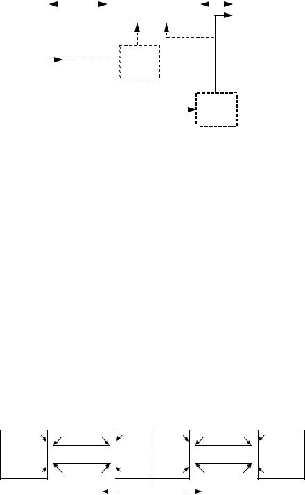
Figure 7-37 shows the minimum allowable voltages in a worst-case topology consisting of a bus-powered hub driving a bus-powered function.
Host or |
|
|
|
|
|
Bus-powered |
|
|
|
|
Low-power |
||||||||
Powered Hub |
|
|
|
|
|
|
Hub |
|
|
|
|
|
|
|
Function |
||||
|
|
|
|
4.735V |
4.640V |
|
|
|
|
|
|
|
4.397V |
4.378V |
|
|
|
|
|
|
|
|
|
|
|
|
|
|
|
|
|
|
|||||||
|
4.750V |
|
|
|
4.625V |
|
|
*4.400V |
|
|
|
|
4.375V |
|
|||||
|
|
|
|
|
|
|
|
4.500V |
|
|
|
|
|
|
|
|
|
||
|
|
|
|
|
|
|
|
|
|
|
|
|
|
|
4.350V |
||||
|
|
|
|
|
|
|
|
|
|
|
|
|
|
|
|||||
|
|
|
|
|
|
|
|
|
|
|
|
|
|
|
|||||
|
|
|
|
|
|
|
|
|
|
|
|
|
|
|
|
|
|
|
|
0.000V |
0.015V |
0.110V |
0.125V |
0.000V |
0.003V |
0.022V |
0.025V |
|
|
|
|
Referenced |
Referenced |
to Source |
to Hub |
*Under transient conditions, supply at hub can drop from 4.400V to 4.070V
Figure 7-37. Worst-case Voltage Drop Topology (Steady State)
138
Universal Serial Bus Specification Revision 1.1
7.2.3 Power Control During Suspend/Resume
Suspend current is a function of unit load allocation. All USB devices initially default to low-power. Lowpower devices or high-power devices operating at low-power are limited to 500 A of suspend current. If the device is configured for high-power and enabled as a remote wakeup source, it may draw up to 2.5mA during suspend. When computing suspend current, the current from VBUS through the bus pull-up and pull-down resistors must be included. Configured bus-powered hubs may also consume a maximum of 2.5mA, with 500 A allocated to each available external port and the remainder available to the hub and its internal functions. If a hub is not configured, it is operating as a low-power device and must limit its suspend current to 500 A.
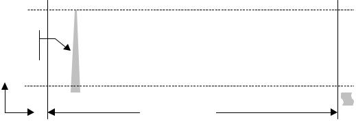
While in the Suspend state, a device may briefly draw more than the average current. The amplitude of the current spike cannot exceed the device power allocation 100mA (or 500mA). A maximum of 1.0 second is allowed for an averaging interval. The average current cannot exceed the average suspend current limit (ICCSH or ICCSL, see Table 7-5) during any 1.0s interval (TSUSAVG1). The profile of the current spike is restricted so the transient response of the power supply (which may be an efficient, low-capacity, trickle power supply) is not overwhelmed. The rising edge of the current spike must be no more than 100mA/ s. Downstream ports must be able to absorb the 500mA peak current spike and meet the voltage droop requirements defined for inrush current during dynamic attach (see Section 7.2.4.1). Figure 7-38 illustrates a typical example profile for an averaging interval. If the supply to the pull-up resistor on D+/D- is derived from VBUS, then the suspend current will never go to zero because the pull-up and pull-down resistors will always draw power.
ICONFIGURED(max)
Edge rate must |
Current Spike |
|
|
||
not exceed |
|
|
100mA/ s |
|
|
|
|
ICCS(H|L) |
I |
|
|
|
0 mA |
|
|
|
|
|
|
|
Averaging Interval
time
Figure 7-38. Typical Suspend Current Averaging Profile
Devices are responsible for handling the bus voltage reduction due to the inductive and resistive effects of the cable. When a hub is in the Suspend state, it must still be able to provide the maximum current per port (one unit load of current per port for bus-powered hubs and five unit loads per port for self-powered hubs). This is necessary to support remote wakeup-capable devices that will power-up while the remainder of the system is still suspended. Such devices, when enabled to do remote wakeup, must drive resume signaling upstream within 10ms of starting to draw the higher, non-suspend current. Devices not capable of remote wakeup must draw the higher current only when not suspended.
When devices wakeup, either by themselves (remote wakeup) or by seeing resume signaling, they must limit the inrush current on VBUS. The target maximum droop in the hub VBUS is 330mV. The device must have sufficient on-board bypass capacitance or a controlled power-on sequence such that the current drawn from the hub does not exceed the maximum current capability of the port at any time while the device is waking up.
139
Universal Serial Bus Specification Revision 1.1
7.2.4 Dynamic Attach and Detach
The act of plugging or unplugging a hub or function must not affect the functionality of another device on other segments of the network. Unplugging a function will stop the transaction between that function and the host. However, the hub to which this function was attached will recover from this condition and will alert the host that the port has been disconnected.
7.2.4.1 Inrush Current Limiting
When a function or hub is plugged into the network, it has a certain amount of on-board capacitance between VBUS and ground. In addition, the regulator on the device may supply current to its output bypass capacitance and to the function as soon as power is applied. Consequently, if no measures are taken to prevent it, there could be a surge of current into the device which might pull the VBUS on the hub below its minimum operating level. Inrush currents can also occur when a high-power function is switched into its high-power mode. This problem must be solved by limiting the inrush current and by providing sufficient capacitance in each hub to prevent the power supplied to the other ports from going out of tolerance. An additional motivation for limiting inrush current is to minimize contact arcing, thereby prolonging connector contact life.
The maximum droop in the hub VBUS is 330mV, or about 10% of the nominal signal swing from the function. In order to meet this requirement, the following conditions must be met:
The maximum load (CRPB) that can be placed at the downstream end of a cable is 10 F in parallel with 44 . The 10 F capacitance represents any bypass capacitor directly connected across the VBUS lines in the function plus any capacitive effects visible through the regulator in the device. The 44 resistance represents one unit load of current drawn by the device during connect.
If more bypass capacitance is required in the device, then the device must incorporate some form of VBUS surge current limiting, such that it matches the characteristics of the above load.
The hub downstream port VBUS power lines must be bypassed (CHPB) with no less than 120 F of lowESR capacitance per hub. Standard bypass methods should be used to minimize inductance and resistance between the bypass capacitors and the connectors to reduce droop. The bypass capacitors themselves should have a low dissipation factor to allow decoupling at higher frequencies.
The upstream port of a hub is also required to meet the above requirements. Furthermore, a bus-powered hub must provide additional surge limiting in the form of a soft-start circuit when it enables power to its downstream ports.
A high-power bus-powered device that is switching from a lower power configuration to a higher power configuration must not cause droop > 330 mV on the VBUS at its upstream hub . The device can meet this by ensuring that changes in the capacitive load it presents do not exceed 10 F.
Signal pins are protected from excessive currents during dynamic attach by being recessed in the connector such that the power pins make contact first. This guarantees that the power rails to the downstream device are referenced before the signal pins make contact. In addition, the signal lines are in a high-impedance state during connect, so that no current flows for standard signal levels.
7.2.4.2 Dynamic Detach
When a device is detached from the network with power flowing in the cable, the inductance of the cable will cause a large flyback voltage to occur on the open end of the device cable. This flyback voltage is not destructive. Proper bypass measures on the hub ports will suppress any coupled noise. The frequency range of this noise is inversely dependent on the length of the cable, to a maximum of 60MHz for a onemeter cable. This will require some low capacitance, very low inductance bypass capacitors on each hub port connector. The flyback voltage and the noise it creates is also moderated by the bypass capacitance on the device end of the cable. Also, there must be some minimum capacitance on the device end of the cable
140