

Universal Serial Bus Specification Revision 1.1
6.5.2 USB Connector Termination Data
Table 6-1 provides the standardized contact terminating assignments by number and electrical value for Series “A” and Series “B” connectors.
Table 6-1. USB Connector Termination Assignment
Contact |
Signal Name |
Typical Wiring |
|
Number |
Assignment |
||
|
|||
|
|
|
|
1 |
VBUS |
Red |
|
|
|
|
|
2 |
D- |
White |
|
|
|
|
|
3 |
D+ |
Green |
|
|
|
|
|
4 |
GND |
Black |
|
|
|
|
|
Shell |
Shield |
Drain Wire |
|
|
|
|
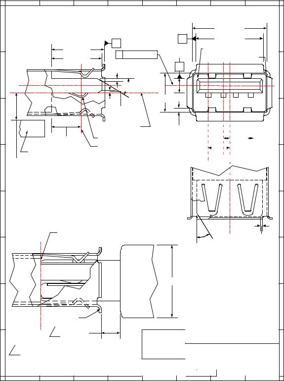
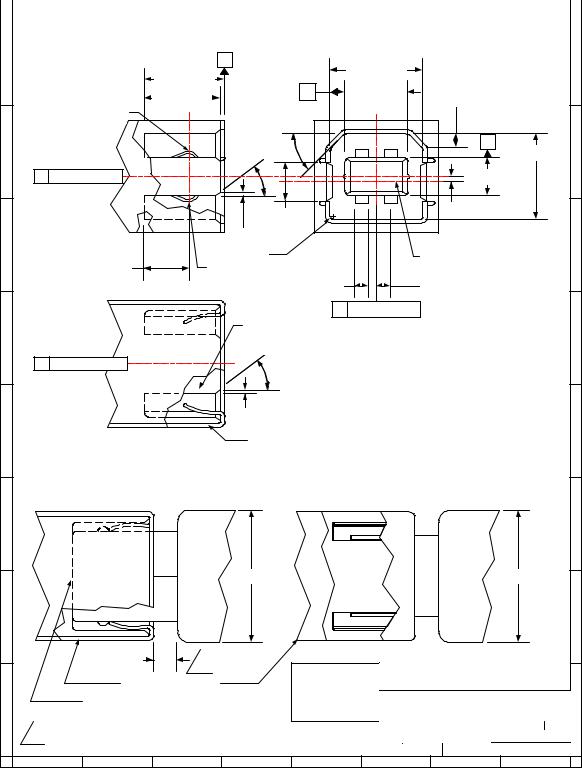
6.5.3 Series “A” and Series “B” Receptacles
Electrical and mechanical interface configuration data for Series "A" and Series "B" receptacles are shown in Figure 6-7 and Figure 6-8. Also, refer to Figure 6-12, Figure 6-13, and Figure 6-14 at the end of this chapter for typical PCB receptacle layouts.
82
Universal Serial Bus Specification Revision 1.1
H
G
F
E
D
C
B
A
8 |
7 |
6 |
5 |
4 |
3 |
2 |
1 |
|
|
USB Series "A" Receptacle Interface |
|
|
|||
|
|
|
|
|
|
12.50 ± 0.10 |
|
|
|
A |
|
C |
|
11.10 ± 0.10 |
|
|
|
|
|
|
|
|
|
|
|
8.88 ± 0.20 |
Center Line |
1.84 ± 0.05 |
R 0.64 ± 0.13 (Typical) |
||
|
|
B |
R 0.32 ± 0.13 (Typical) |
||||
|
|
8.38 ± 0.08 |
|
|
|||
|
|
0.50 ± 0.10 |
B |
|
|
|
|
|
|
|
300 ± 20 (2) |
|
1 |
2 3 |
4 |
|
|
|
5.12 ± 0.10 |
|
|
|
|
|
|
0.38 ± 0.13 |
|
|
|
|
|
4.98 ± 0.25
Printed Circuit Board
4.13 REF
All dimensions are in millimeters otherwise noted.
|
Center Line of 5.12 |
|
|
|
|
|
|
|
|
|
|
|
|
|
|
|
|
|
||
|
|
|
|
|
|
|
|
|
|
|
|
|
|
|
|
|
|
|||
|
|
|
0.64 ± 0.13 (8) |
|
|
|
|
|
|
|
|
|
|
|
|
|
||||
|
|
|
|
|
|
|
|
|
|
|
|
|
|
|
|
|||||
|
|
|
|
|
|
|
|
|
|
|
|
|
||||||||
|
|
|
|
|
|
|
|
|
|
|
|
|
|
|
|
|
|
|||
|
|
|
|
|
|
|
|
|
|
|
|
|
|
|
|
|
|
|
|
|
|
|
Receptacle Contact |
|
|
1.00 ± 0.05 (2) |
|
|
|
|
|
|
|
|
|
|
|
|
|||
|
|
Contact Point |
|
|
|
|
3.50 ± 0.05 (2) |
|
|
|
|
|
|
|
|
|
|
|
||
|
|
|
|
|
|
|
|
|
|
|
1.00 ± 0.05 (4) |
|||||||||
|
|
|
|
|
|
|
|
|
|
|
|
|||||||||
|
|
|
|
|
|
|
|
|
|
|
|
|
|
|
|
|
|
|||
m( m ) unless |
|
|
|
|
|
|
C |
Center Line |
|
|||||||||||
|
|
|
|
|
|
|
|
|
|
|
|
|
|
|
||||||
|
|
|
|
|
|
|
|
|
|
|
|
|
|
|
||||||
|
|
|
|
|
|
|
|
|
|
|
|
|
|
|
||||||
|
|
|
|
|
|
|
|
|
|
|
|
|
|
|
||||||
|
|
|
|
|
|
|
|
|
|
|
|
|
|
|
||||||
|
|
|
|
|
|
|
|
|
|
|
|
|
|
|
||||||
|
|
|
|
|
|
|
|
|
|
|
|
|
|
|
||||||
|
|
|
|
|
|
|
|
|
|
|
|
|
|
|
||||||
USB Series "A" Receptacle and Plug
Mating Features
Fully Mated Series "A"
|
Receptacle and Plug |
|
|
|
|
0.50 ± 0.10 (2) |
||
|
|
|
|
|
|
|
||
|
|
|
|
|
300 ± 20 (2) |
|
|
|
|
|
|
|
Boot |
|
|
|
|
|
|
|
|
Overmold |
8.0 MAX |
|
|
|
|
|
|
|
|
|
|
|
|
|
Receptacle Flange |
|
|
|
|
|
|
|
|
1 |
2.67 MIN |
|
|
Interface and Mating Drawing |
|||
|
|
|
|
|
||||
1 |
Allow a minimum spacing of 2.67mm between |
|
Series "A" Receptacle |
|||||
the face of the receptacle and the plug |
|
|
||||||
|
|
|
|
|
|
|
||
|
overmold boot. |
|
|
|
SIZE |
DATE |
DRAWING NUMBER |
REV |
|
|
|
|
|
A |
2/98 |
N/A |
C |
|
|
|
|
|
SCALE: |
N/A |
SHEET |
1 of 1 |
8 |
7 |
6 |
5 |
4 |
3 |
|
2 |
1 |
H
G
F
E
D
C
B
A
Figure 6-7. USB Series "A" Receptacle Interface and Mating Drawing
83
Universal Serial Bus Specification Revision 1.1
8 |
7 |
6 |
5 |
4 |
3 |
2 |
1 |
USB Series "B" Receptacle Interface
H |
|
A |
|
|
8.45 + 0.10 |
|
H |
|
|
|
|
|
|
||||
|
|
8.88 + 0.20 |
|
|
|
|
||
|
|
|
|
5.60 + 0.10 |
|
|
||
|
|
8.38 + 0.08 |
|
C |
1.63 + 0.05 (2) |
|
||
|
|
|
|
|
|
|
||
Receptacle Contact |
450 + |
0.50 |
(2) |
|
|
|
|
|
|
|
|
|
|
|
|||
|
|
300 + |
20 (4) |
|
|
|
B |
|
G |
|
|
2 |
1 |
7.78 + 0.10 |
G |
||
|
|
|
|
|
|
|
||
B |
Center Line |
|
|
|
|
|
3.18 + 0.05 |
|
|
|
|
|
|
3 |
4 |
0.80 + 0.08 |
|
|
|
3.67 + 0.08 |
|
|
|
|||
|
|
|
|
|
|
|||
|
|
0.38 + 0.13 (4) |
|
|
|
|
||
F |
|
R 0.38 (6) |
|
|
|
3.67 Center Line |
F |
|
|
|
|
|
|
|
|||
|
4.98 + 0.25 |
Contact Point |
|
|
|
|
||
|
|
|
|
|
|
|||
|
|
|
1.00 + 0.05 (4) |
|
|
1.25 + 0.10 (4) |
|
|
|
|
|
|
C |
Center Line |
|
|
|
|
|
Receptacle Housing |
|
|
|
|||
E |
|
300 + 20 |
(2) |
|
|
|
E |
|
B |
Center Line |
|
|
|
|
|
|
|
|
|
|
|
|
All dimensions are in millimeters (m m ) |
|
||
|
|
|
|
|
unless otherwise noted. |
|
||
|
|
0.50 + 0.10 (2) |
|
|
|
|
||
D |
|
Receptacle Shell |
|
|
|
D |
||
|
|
|
|
|
|
|||
USB Series "B" Receptacle and Plug Mating Features
C |
|
Boot |
|
|
|
|
Boot |
|
C |
|
|
|
|
|
|
|
|
||
|
|
Overmold |
10.5 MAX |
|
|
|
Overmold |
11.5 MAX |
|
|
|
|
|
|
|
|
|||
B |
|
|
|
|
|
|
|
|
B |
|
2.67 MIN |
1 |
|
|
|
|
|
|
|
|
|
|
|
Interface and Mating Drawing |
|||||
|
Receptacle Shell |
|
|
||||||
|
|
|
|
|
|
|
|
||
A |
Fully Mated Plug and Receptacle |
|
USB Series "B" Receptacle |
||||||
|
|
|
|
|
|
|
|
A |
|
1 |
Allow a minimum spacing of 2.67mm between the |
|
SIZE |
DATE |
D R A W I N G N U M B E R |
REV |
|||
face of the receptacle and the plug overmold boot. |
|
A |
2/98 |
|
N/A |
C |
|||
|
|
SCALE: |
N/A |
|
SHEET |
1 of 1 |
|||
|
|
|
|
|
|
||||
8 |
7 |
6 |
5 |
4 |
3 |
|
2 |
|
1 |
Figure 6-8. USB Series "B" Recptacle Interface and Mating Drawing
84
Universal Serial Bus Specification Revision 1.1
6.5.3.1 Receptacle Injection M olded Thermoplastic Insulator Material
Minimum UL 94-V0 rated, thirty percent (30%) glass-filled polybutylene terephthalate (PBT) or polyethylene terephthalate (PET) or better.
Typical Colors: Black, Gray and Natural.
Flammability Characteristics: UL 94-V0 rated.
Flame Retardant Package must meet or exceed the requirements for UL, CSA, VDE, et cetera.
Oxygen Index (LOI): Greater than 21%. ASTM D 2863.
6.5.3.2Receptacle Shell Mate rials
Substrate Material: 0.30 + 0.05 mm phosphor bronze, nickel silver or other copper based high strength materials.
Plating:
1.Underplate: Optional. Minimum 1.00 micrometers (40 microinches) Nickel. In addition, manufacturer may use a copper underplate beneath the nickel.
2.Outside: Minimum 2.5 micrometers (100 microinches) Bright Tin or Bright Tin-Lead.
6.5.3.3Receptacle Contact M aterials
Substrate Material: 0.30 + 0.05 mm minimum half-hard phosphor bronze or other the high strength copper based material.
Plating: Contacts are to be selectively plated.
A.Option I
1.Underplate: Minimum 1.25 micrometers (50 microinches) Nickel. Copper over base material is optional.
2.Mating Area: Minimum 0.05 micrometers (2 microinches) Gold over a minimum of 0.70 micrometers (28 microinches) Palladium.
3.Solder Tails: Minimum 3.8 micrometers (150 microinches) Bright Tin-Lead over the underplate.
B.Option II
1.Underplate: Minimum 1.25 micrometers (50 microinches) Nickel. Copper over base material is optional.
2.Mating Area: Minimum 0.05 micrometers (2 microinches) Gold over a minimum of 0.75 micrometers (30 microinches) Palladium-Nickel.
3.Solder Tails: Minimum 3.8 micrometers (150 microinches) Bright Tin-Lead over the underplate.
C.Option III
1.Underplate: Minimum 1.25 micrometers (50 microinches) Nickel. Copper over base material is optional.
2.Mating Area: Minimum 0.75 micrometers (30 microinches) Gold.
3.Solder Tails: Minimum 3.8 micrometers (150 microinches) Bright Tin-Lead over the underplate.
85