

Литература / И еще что-то / usb 1.0 / USBCableECN_final
.pdfUSB Engineering Change Notice – USB Cable Parameters
|
TITLE: |
|
|
|
USB Cable Parameters |
|
DATE: |
|
|
|
Oct 7, 1999 |
|
AFFECTED DOCUMENT(S): |
|
USB Specification Rev 1.1 |
||
|
SPONSOR: |
|
Venkat Iyer - Intel Corporation |
||
|
1.1 |
Clarification / Motivation |
|
|
|
The motivation for this ECN is two-fold:
1.Testing of USB cables has revealed certain areas where the spec was not clear or silent. This ECN addresses these areas.
2.When USB 2.0 is introduced, the end user should perceive this as just a faster version of USB. All cables and connectors should look mechanically the same. Testing on existing cables has shown that today’s compliant cables will also support USB 2.0 signaling rates, but there are areas where the parameters on the 1.1 spec need to be extended or clarified to ensure operation at USB 2.0 speeds.
By incorporating the following changes as an ECN to the USB 1.1 spec both of the above motivations can be met. It will also ensure that the one and only USB cable spec is available to industry as quickly as possible.
Summary of changes:
∙Add to the frequency range of the attenuations table (Table 7-4) to include 200MHz <3.2db and 400MHz < 5.8db.
∙Specify that the common mode impedance (Zcm) must be 30 ohms +/- 30%
∙Clarify section 7.1.16 so that one way cable delay is 5.2 ns/m (not 26ns regardless of length).
∙Tighten cable skew (Sec 7.1.3) to 100ps from 400ps
∙DC resistance from plug shell to plug shell < .6 ohms
1.2Impact on Existing Devices
About 20 cables, from various vendors and of various lengths, were tested at several different labs. That testing revealed that all cables that were compliant with the current USB specification easily met the proposed new criteria. A few test cables would not meet the new criteria, but those cables were also not compliant with the current specification. So the impact on current USB cables is none if they are USB 1.1 compliant.
These changes will not effect existing USB devices or host.
These changes do not have any effect on software.
1.3USB 1.1 Specification Changes
∙The following changes to the attenuation spec (Table 7-4) are needed to ensure that cables perform adequately with the higher speed, lower amplitude signaling used in USB 2.0. The range over which attenuation is specified has been increased from 96 Mhz to 400 Mhz. The attenuation numbers below 96 Mhz have been preserved. The attenuation of a sampling of cables that are compliant with the USB 1.1 spec has been tested at frequencies above 96 Mhz. These cables met the attenuation numbers
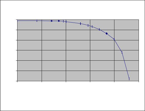
called out here. The attenuation table has also been converted into a continuous curve in order to define the maximum allowable attenuation at any frequency.
Maximum Allowable Cable Loss
(dB) |
0 |
|
|
|
|
|
|
|
|
|
|
|
|
Attenuation |
-1 |
|
|
|
|
|
-2 |
|
|
|
|
|
|
|
|
|
|
|
|
|
Allowable |
-3 |
|
|
|
|
|
-4 |
|
|
|
|
|
|
|
|
|
|
|
|
|
Maximum |
-5 |
|
|
|
|
|
-6 |
|
|
|
|
|
|
010.0 |
100.0 |
000.1 |
000.10 |
000.100 |
000.1000 |
Frequency (in MHz, log scale)
Action: replace Table 7-4 with above graph. Add the following text:
The attenuation curve (with straight line interpolation between consecutive points) of the cable assembly should be above or at the curve shown for all frequencies up to 400 Mhz.
∙The common-mode impedance of the cable affects the signal quality of a full-speed EOP and the start and end transitions of a high-speed packet. This change closes an area overlooked in the USB 1.1
spec.
The common mode impedance Zcm of the D+/D- line must be 30 ohms +/-30%. Action: In sec 7.1.1.1 replace “characteristic impedance …. +/- 15%” with the following
“characteristic differential impedance …. +/- 15% and common mode impedance Zcm of 30 ohms +/- 30%” Action: Add common mode cable entry into Table 7-9: min=21 ohms, max=39 ohms
∙Sec. 7.1.16 of the USB 1.1 spec requires the one way cable delay to be less than 26ns. It is possible for some poorly engineered cables to meet this requirement by shortening the cable. This could adversely affect signal quality at USB 2.0 speeds. This is a clarification.
The cable delay must be less than 5.2 ns/m.
Action: In sec. 7.1.16, add the following sentence at the end of the first paragraph. “The cable delay should also be less than 5.2 ns per meter.”

∙Sec. 7.1.3 of USB 1.1 requires the cable skew to be less than 400 ps. This number is too large given the shorter bit times of USB 2.0 signaling. The skew measured for a sampling of USB 1.1 compliant cables was well within the tightened number specified below.
The cable skew must be less than 100 ps.
Action: In sec 7.1.3 replace 400 with 100.
∙The shield impedance is a measure of the EMI susceptibility of the cable. While the USB 1.1 spec specifies braid coverage, it doesn’t specify the impedance. This is a clarification to the USB 1.1 spec.
∙Some cables which exhibited severe EMI leakage were investigated for construction problems. It was observed that such cables invariably make poor to no ohmic contact between braid and shell. This is a clarification to the USB 1.1 spec.
Action: Add the following sentence to the end of section 6.6.3: “ The DC resistance from plug shell to plug shell (or end of integrated cable) should be less than 0.6 ohms.”
Measurement methods:
The parameters should continue to be measured as specified in the USB 1.1 specification.
1.4Cable Testing Specification Changes
Action:
In Table 3-1 of the cable and connector compliance test plan, add the following:
The common mode impedance is measured with a TDR with tr less than 0.2 ns. It is measured at 2 ns from the plug closest to the launching connector on the TDR display. For short cables (one way propagation delay less than 2 ns), Zcm is measured at the middle of the cable.
In Table 3-1, add a test for plug shell to plug shell resistance using test procedure EIA 364-23 and performance requirement of max 0.6 ohms when measured at 100 ma, 5V DC open circuit.
In Table 3-1, add a sentence to the propagation delay test procedure to divide the delay by the length of the cable and record the result.