

- •Chapter 1
- •1.1 Motivation
- •1.2 Objective of the Specification
- •1.3 Scope of the Document
- •1.4 Document Organization
- •Chapter 2
- •Chapter 3
- •3.1 Goals for the Universal Serial Bus
- •3.2 Taxonomy of Application Space
- •3.3 Feature List
- •Chapter 4
- •4.1 USB System Description
- •4.1.1 Bus Topology
- •4.2 Physical Interface
- •4.2.1 Electrical
- •4.2.2 Mechanical
- •4.3 Power
- •4.3.1 Power Distribution
- •4.3.2 Power Management
- •4.4 Bus Protocol
- •4.5 Robustness
- •4.5.1 Error Detection
- •4.5.2 Error Handling
- •4.6 System Configuration
- •4.6.1 Attachment of USB Devices
- •4.6.2 Removal of USB Devices
- •4.6.3 Bus Enumeration
- •4.7 Data Flow Types
- •4.7.1 Control Transfers
- •4.7.2 Bulk Transfers
- •4.7.3 Interrupt Transfers
- •4.7.4 Isochronous Transfers
- •4.7.5 Allocating USB Bandwidth
- •4.8 USB Devices
- •4.8.1 Device Characterizations
- •4.8.2 Device Descriptions
- •4.9 USB Host: Hardware and Software
- •4.10 Architectural Extensions
- •Chapter 5
- •5.1 Implementer Viewpoints
- •5.2 Bus Topology
- •5.2.1 USB Host
- •5.2.2 USB Devices
- •5.2.3 Physical Bus Topology
- •5.2.4 Logical Bus Topology
- •5.2.5 Client Software-to-function Relationship
- •5.3 USB Communication Flow
- •5.3.1 Device Endpoints
- •5.3.2 Pipes
- •5.4 Transfer Types
- •5.5 Control Transfers
- •5.5.1 Control Transfer Data Format
- •5.5.2 Control Transfer Direction
- •5.5.3 Control Transfer Packet Size Constraints
- •5.5.4 Control Transfer Bus Access Constraints
- •5.5.5 Control Transfer Data Sequences
- •5.6 Isochronous Transfers
- •5.6.1 Isochronous Transfer Data Format
- •5.6.2 Isochronous Transfer Direction
- •5.6.3 Isochronous Transfer Packet Size Constraints
- •5.6.4 Isochronous Transfer Bus Access Constraints
- •5.6.5 Isochronous Transfer Data Sequences
- •5.7 Interrupt Transfers
- •5.7.1 Interrupt Transfer Data Format
- •5.7.2 Interrupt Transfer Direction
- •5.7.3 Interrupt Transfer Packet Size Constraints
- •5.7.4 Interrupt Transfer Bus Access Constraints
- •5.7.5 Interrupt Transfer Data Sequences
- •5.8 Bulk Transfers
- •5.8.1 Bulk Transfer Data Format
- •5.8.2 Bulk Transfer Direction
- •5.8.3 Bulk Transfer Packet Size Constraints
- •5.8.4 Bulk Transfer Bus Access Constraints
- •5.8.5 Bulk Transfer Data Sequences
- •5.9 Bus Access for Transfers
- •5.9.1 Transfer Management
- •5.9.2 Transaction Tracking
- •5.9.3 Calculating Bus Transaction Times
- •5.9.4 Calculating Buffer Sizes in Functions and Software
- •5.9.5 Bus Bandwidth Reclamation
- •5.10 Special Considerations for Isochronous Transfers
- •5.10.1 Example Non-USB Isochronous Application
- •5.10.2 USB Clock Model
- •5.10.3 Clock Synchronization
- •5.10.4 Isochronous Devices
- •5.10.5 Data Prebuffering
- •5.10.6 SOF Tracking
- •5.10.7 Error Handling
- •5.10.8 Buffering for Rate Matching
- •Chapter 6
- •6.1 Architectural Overview
- •6.3 Cable
- •6.4 Cable Assembly
- •6.4.1 Detachable Cable Assemblies
- •6.4.3 Low-speed Captive Cable Assemblies
- •6.4.4 Prohibited Cable Assemblies
- •6.5.1 USB Icon Location
- •6.5.2 USB Connector Termination Data
- •6.5.3 Series “A” and Series “B” Receptacles
- •6.5.4 Series “A” and Series “B” Plugs
- •6.6.1 Description
- •6.6.2 Construction
- •6.6.3 Electrical Characteristics
- •6.6.4 Cable Environmental Characteristics
- •6.6.5 Listing
- •6.7 Electrical, Mechanical and Environmental Compliance Standards
- •6.7.1 Applicable Documents
- •6.8 USB Grounding
- •Chapter 7
- •7.1 Signaling
- •7.1.1 USB Driver Characteristics
- •7.1.2 Data Signal Rise and Fall
- •7.1.3 Cable Skew
- •7.1.4 Receiver Characteristics
- •7.1.5 Device Speed Identification
- •7.1.6 Input Characteristics
- •7.1.7 Signaling Levels
- •7.1.8 Data Encoding/Decoding
- •7.1.9 Bit Stuffing
- •7.1.10 Sync Pattern
- •7.1.11 Data Signaling Rate
- •7.1.12 Frame Interval and Frame Interval Adjustment
- •7.1.13 Data Source Signaling
- •7.1.14 Hub Signaling Timings
- •7.1.15 Receiver Data Jitter
- •7.1.16 Cable Delay
- •7.1.17 Cable Attenuation
- •7.1.18 Bus Turn-around Time and Inter-packet Delay
- •7.1.19 Maximum End-to-end Signal Delay
- •7.2 Power Distribution
- •7.2.1 Classes of Devices
- •7.2.2 Voltage Drop Budget
- •7.2.3 Power Control During Suspend/Resume
- •7.2.4 Dynamic Attach and Detach
- •7.3 Physical Layer
- •7.3.1 Regulatory Requirements
- •7.3.2 Bus Timing/Electrical Characteristics
- •7.3.3 Timing Waveforms
- •Chapter 8
- •8.1 Bit Ordering
- •8.2 SYNC Field
- •8.3 Packet Field Formats
- •8.3.1 Packet Identifier Field
- •8.3.2 Address Fields
- •8.3.3 Frame Number Field
- •8.3.4 Data Field
- •8.3.5 Cyclic Redundancy Checks
- •8.4 Packet Formats
- •8.4.1 Token Packets
- •8.4.2 Start-of-Frame Packets
- •8.4.3 Data Packets
- •8.4.4 Handshake Packets
- •8.4.5 Handshake Responses
- •8.5 Transaction Formats
- •8.5.1 Bulk Transactions
- •8.5.2 Control Transfers
- •8.5.3 Interrupt Transactions
- •8.5.4 Isochronous Transactions
- •8.6 Data Toggle Synchronization and Retry
- •8.6.1 Initialization via SETUP Token
- •8.6.2 Successful Data Transactions
- •8.6.3 Data Corrupted or Not Accepted
- •8.6.4 Corrupted ACK Handshake
- •8.6.5 Low-speed Transactions
- •8.7 Error Detection and Recovery
- •8.7.1 Packet Error Categories
- •8.7.2 Bus Turn-around Timing
- •8.7.3 False EOPs
- •8.7.4 Babble and Loss of Activity Recovery
- •Chapter 9
- •9.1 USB Device States
- •9.1.1 Visible Device States
- •9.1.2 Bus Enumeration
- •9.2 Generic USB Device Operations
- •9.2.1 Dynamic Attachment and Removal
- •9.2.2 Address Assignment
- •9.2.3 Configuration
- •9.2.4 Data Transfer
- •9.2.5 Power Management
- •9.2.6 Request Processing
- •9.2.7 Request Error
- •9.3 USB Device Requests
- •9.3.1 bmRequestType
- •9.3.2 bRequest
- •9.3.3 wValue
- •9.3.4 wIndex
- •9.3.5 wLength
- •9.4 Standard Device Requests
- •9.4.1 Clear Feature
- •9.4.2 Get Configuration
- •9.4.3 Get Descriptor
- •9.4.4 Get Interface
- •9.4.5 Get Status
- •9.4.6 Set Address
- •9.4.7 Set Configuration
- •9.4.8 Set Descriptor
- •9.4.9 Set Feature
- •9.4.10 Set Interface
- •9.4.11 Synch Frame
- •9.5 Descriptors
- •9.6 Standard USB Descriptor Definitions
- •9.6.1 Device
- •9.6.2 Configuration
- •9.6.3 Interface
- •9.6.4 Endpoint
- •9.6.5 String
- •9.7 Device Class Definitions
- •9.7.1 Descriptors
- •9.7.2 Interface(s) and Endpoint Usage
- •9.7.3 Requests
- •Chapter 10
- •10.1 Overview of the USB Host
- •10.1.1 Overview
- •10.1.2 Control Mechanisms
- •10.1.3 Data Flow
- •10.1.4 Collecting Status and Activity Statistics
- •10.1.5 Electrical Interface Considerations
- •10.2 Host Controller Requirements
- •10.2.1 State Handling
- •10.2.2 Serializer/Deserializer
- •10.2.3 Frame Generation
- •10.2.4 Data Processing
- •10.2.5 Protocol Engine
- •10.2.6 Transmission Error Handling
- •10.2.7 Remote Wakeup
- •10.2.8 Root Hub
- •10.2.9 Host System Interface
- •10.3 Overview of Software Mechanisms
- •10.3.1 Device Configuration
- •10.3.2 Resource Management
- •10.3.3 Data Transfers
- •10.3.4 Common Data Definitions
- •10.4 Host Controller Driver
- •10.5 Universal Serial Bus Driver
- •10.5.1 USBD Overview
- •10.5.2 USBD Command Mechanism Requirements
- •10.5.3 USBD Pipe Mechanisms
- •10.5.4 Managing the USB via the USBD Mechanisms
- •10.5.5 Passing USB Preboot Control to the Operating System
- •10.6 Operating System Environment Guides
- •Chapter 11
- •11.1 Overview
- •11.1.1 Hub Architecture
- •11.1.2 Hub Connectivity
- •11.2 Hub Frame Timer
- •11.2.1 Frame Timer Synchronization
- •11.2.2 EOF1 and EOF2 Timing Points
- •11.3 Host Behavior at End-of-Frame
- •11.3.1 Latest Host Packet
- •11.3.2 Packet Nullification
- •11.3.3 Transaction Completion Prediction
- •11.4 Internal Port
- •11.4.1 Inactive
- •11.4.2 Suspend Delay
- •11.4.3 Full Suspend (Fsus)
- •11.4.4 Generate Resume (GResume)
- •11.5 Downstream Ports
- •11.5.1 Downstream Port State Descriptions
- •11.6 Upstream Port
- •11.6.1 Receiver
- •11.6.2 Transmitter
- •11.7 Hub Repeater
- •11.7.1 Wait for Start of Packet from Upstream Port (WFSOPFU)
- •11.7.2 Wait for End of Packet from Upstream Port (WFEOPFU)
- •11.7.3 Wait for Start of Packet (WFSOP)
- •11.7.4 Wait for End of Packet (WFEOP)
- •11.8 Bus State Evaluation
- •11.8.1 Port Error
- •11.8.2 Speed Detection
- •11.8.3 Collision
- •11.9 Suspend and Resume
- •11.10 Hub Reset Behavior
- •11.10.1 Hub Receiving Reset on Upstream Port
- •11.11 Hub Port Power Control
- •11.11.1 Multiple Gangs
- •11.12 Hub I/O Buffer Requirements
- •11.12.1 Pull-up and Pull-down Resistors
- •11.12.2 Edge Rate Control
- •11.13 Hub Controller
- •11.13.1 Endpoint Organization
- •11.13.2 Hub Information Architecture and Operation
- •11.13.3 Port Change Information Processing
- •11.13.4 Hub and Port Status Change Bitmap
- •11.13.5 Over-current Reporting and Recovery
- •11.14 Hub Configuration
- •11.15 Descriptors
- •11.15.1 Standard Descriptors
- •11.15.2 Class-specific Descriptors
- •11.16 Requests
- •11.16.1 Standard Requests
- •11.16.2 Class-specific Requests
- •Index
Universal Serial Bus Specification Revision 1.1
data packet and the handshake packet (refer to Chapter 8). The device expecting the response will not time out before 16 bit times but will timeout before 18 bit times (measured at the data pins of the device from the SE0-to-J transition at the end of the EOP). The host will wait at least 18 bit times for a response to start before it will start a new transaction.
Figure 7-31 depicts the configuration of six signal hops (cables) that results in allowable worst-case signal delay. The maximum propagation delay from the upstream end of a hub’s cable to any downstream port connector is 70ns.
Host |
|
|
|
|
|
|
|
|
|
|
|
|
|
|
|
Hub 5 |
Hub 4 |
|
|
Hub 3 |
Hub 2 |
Hub 1 |
Function |
||||||||
Controller |
|
|
|||||||||||||
|
|
|
|
|
|
|
|
|
|
|
|
|
|
|
|
|
|
|
|
|
|
|
|
|
|
|
|
|
|
|
|
|
|
|
|
|
|
|
|
|
|
|
|
|
|
|
|
|
|
|
|
|
|
|
|
|
|
|
|
|
|
|
|
|
Cable Delay + Hub Delay 70ns (each) |
|
Propagation Delay 30ns |
||||||||||||
Figure 7-31. Worst-case End to End Signal Delay Model
7.2 Power Distribution
This section describes the USB power distribution specification.
7.2.1 Classes of Devices
The power source and sink requirements of different device classes can be simplified with the introduction of the concept of a unit load. A unit load is defined to be 100mA. The number of unit loads a device can draw is an absolute maximum, not an average over time. A device may be either low-power at one unit load or high-power, consuming up to five unit loads. All devices default to low-power. The transition to high-power is under software control. It is the responsibility of software to ensure adequate power is available before allowing devices to consume high-power.
The USB supports a range of power sourcing and power consuming agents; these include the following:
Root port hubs: Are directly attached to the USB Host Controller. Hub power is derived from the same source as the Host Controller. Systems that obtain operating power externally, either AC or DC must supply at least five unit loads to each port. Such ports are called high-power ports. Batterypowered systems may supply either one or five unit loads. Ports that can supply only one unit load are termed low-power ports.
Bus-powered hubs: Draw all of their power for any internal functions and downstream ports from VBUS on the hub’s upstream port. Bus-powered hubs may only draw up to one unit load upon powerup, and five unit loads after configuration. The configuration power is split between allocations to the hub, any non-removable functions and the external ports. External ports in a bus-powered hub can supply only one unit load per port regardless of the current draw on the other ports of that hub. The hub must be able to supply this port current when the hub is in the Active or Suspend state.
Self-powered hubs: Power for the internal functions and downstream ports does not come from VBUS. However, the USB interface of the hub may draw up to one unit load from its upstream VBUS to allow the interface to function when the remainder of the hub is powered down. Hubs that obtain operating power externally (from the USB) must supply five unit loads to each port. Battery-powered hubs may supply either one or five unit loads per port.
Low-power bus-powered functions: All power to these devices comes from VBUS. They may draw no more than one unit load at any time.
High-power bus-powered functions: All power to these devices comes from VBUS. They must draw no more than one unit load upon power-up and may draw up to five unit loads after being configured.
134
Universal Serial Bus Specification Revision 1.1
Self-powered functions: May draw up to one unit load from VBUS to allow the USB interface to function when the remainder of the function is powered down. All other power comes from an external (to the USB) source.
No device shall supply (source) current on VBUS at its upstream port at any time. From VBUS on its upstream port, a device may only draw (sink) current. They may not provide power to the pull-up resistor on D+/D- unless VBUS is present (see Section 7.1.5). On power-up, a device needs to ensure that its upstream port is not driving the bus, so that the device is able to receive the reset signaling. Devices must also ensure that the maximum operating current drawn by a device is one unit load, until configured. Any device that draws power from the bus must be able to detect lack of activity on the bus, enter the Suspend state and reduce its current consumption from VBUS (refer to Section 7.2.3 and Section 9.2.5.1).
7.2.1.1 Bus-powered Hubs
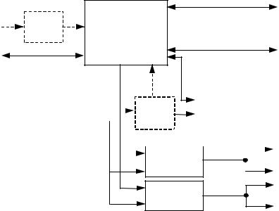
Bus-powered hub power requirements can be met with a power control circuit such as the one shown in Figure 7-32. Bus-powered hubs often contain at least one non-removable function. Power is always available to the hub’s controller, which permits host access to power management and other configuration registers during the enumeration process. A non-removable function(s) may require that its power be switched, so that upon power-up the entire device (hub and non-removable functions) draws no more than one unit load. Power switching on any non-removable function may be implemented either by removing its power or by shutting off the clock. Switching on the non-removable function is not required if the aggregate power drawn by it and the Hub Controller is less than one unit load. However, as long as the hub port associated with the function is in the Power-off state, the function must be logically reset and the device must appear to be not connected. The total current drawn by a bus-powered device is the sum of the current to the Hub Controller, any non-removable function(s), and the downstream ports.
Figure 7-32 shows the partitioning of power based upon the maximum upstream current draw of five unit loads: one unit load for the Hub Controller and the non-removable function, and one unit load for each of the external downstream ports. If more than four external ports are required, then the hub will need to be self-powered. If the non-removable function(s) and Hub Controller draw more than one unit load, then the number of external ports must be appropriately reduced. Power control to a bus-powered hub may require a regulator. If present, the regulator is always enabled to supply the Hub Controller. The regulator can also power the non-removable functions(s). Inrush current limiting must also be incorporated into the regulator subsystem.
Downstream
Upstream Hub Controller 
 Data Ports
Data Port
|
|
|
|
Iportctrl |
|
|
|
|
|
|
|
|
|
|
||
|
|
|
|
|
|
|
|
|
|
|
|
|
|
|
|
|
Upstream VBUS |
|
|
|
Regulator |
|
On/Off |
|
|
Non-removable |
|
|
|||||
|
|
|
|
|
|
|
|
|
|
|
||||||
5 unit loads |
|
|
|
|
|
|
|
|
|
Function |
|
|
||||
|
|
|
|
|
|
|
|
|
|
|
|
|
|
|
||
|
|
|
|
|
|
|
1 unit load - Iportctrl |
|
|
|
|
|
|
|||
|
|
|
On/Off |
|
|
|
|
|
|
|
|
|
|
|||
|
|
|
|
|
|
|
|
|
|
|
|
|
||||
|
|
|
|
Switch |
|
|
|
|
|
1 unit load/port |
|
|
Downstream VBUS |
|||
|
|
|
|
|
|
|
|
|
|
|
||||||
|
|
|
|
|
|
|
|
|
|
|
||||||
|
|
|
|
|
|
|
|
|
|
|
|
|
|
|
|
|
|
|
|
|
|
|
|
|
|
|
|
|
|
|
|
|
|
|
|
|
|
|
|
|
|
|
|
|
|
|
|
|
|
|
Figure 7-32. Compound Bus-powered Hub
Power to external downstream ports of a bus-powered hub must be switched. The Hub Controller supplies a software controlled on/off signal from the host, which is in the “off” state when the device is powered up or after reset signaling. When switched to the “on” state, the switch implements a soft turn-on function that
135
Universal Serial Bus Specification Revision 1.1
prevents excessive transient current from being drawn from the upstream port. The voltage drop across the upstream cable, connectors, and switch in a bus-powered hub must not exceed 350mV at maximum rated current.
7.2.1.2 Self-powered Hubs
Self-powered hubs have a local power supply that furnishes power to any non-removable functions and to all downstream ports, as shown in Figure 7-33. Power for the Hub Controller, however, may be supplied from the upstream VBUS (a “hybrid” powered hub) or the local power supply. The advantage of supplying the Hub Controller from the upstream supply is that communication from the host is possible even if the device’s power supply remains off. This makes it possible to differentiate between a disconnected and an unpowered device. If the hub draw power for its upstream port from VBUS, it may not draw more than one unit load.
Upstream VBUS |
Regulator |
1 unit load (max) |
Hub Controller
Upstream
Data Port
.
.
.
Downstream
Data Ports
|
|
|
|
|
|
|
|
|
|
Non-removable |
|
|
Local Power |
|
|
|
Regulator |
|
|
||||||
|
|
|
|
Function |
|
|||||||
Supply |
|
|
|
|
|
|
|
|
|
|||
|
|
|
On/Off |
|
|
|
|
|
||||
|
|
|
|
|
|
|
|
|
|
|||
|
|
|
|
|
|
|
|
|
||||
|
|
|
|
|
|
|
|
|
|
|||
|
|
|
|
|
|
|
||||||
|
|
|
|
|
|
|
|
|
|
|
. |
|
|
|
|
|
|
|
|
|
|
|
|||
|
|
|
|
|
|
|
|
Current Limit |
|
. |
||
|
|
|
|
|
|
|
|
|
|
|
|
|
5 unit loads/port
Downstream VBUS
Current Limit |
. |
. |
Figure 7-33. Compound Self-powered Hub
The number of ports that can be supported is limited only by the address capability of the hub and the local supply.
Self-powered hubs may experience loss of power. This may be the result of disconnecting the power cord or exhausting the battery. Under these conditions, the hub may force a re-enumeration of itself as a buspowered hub. This requires the hub to implement port power switching on all external ports. When power is lost, the hub must ensure that upstream current does not exceed low-power. All the rules of a buspowered hub then apply.
7.2.1.2.1 Over-current Protection
The host and all self-powered hubs must implement over-current protection for safety reasons, and the hub must have a way to detect the over-current condition and report it to the USB software. Should the aggregate current drawn by a gang of downstream ports exceed a preset value, the over-current protection circuit removes or reduces power from all affected downstream ports. The over-current condition is reported through the hub to Host Controller, as described in Section 11.13.5. The preset value cannot exceed 5.0 A and must be sufficiently above the maximum allowable port current such that transient currents (e.g. during power up or dynamic attach or reconfiguration) do not trip the over-current protector.
136
Universal Serial Bus Specification Revision 1.1
If an over-current condition occurs on any port, subsequent operation of the USB is not guaranteed, and once the condition is removed, it may be necessary to reinitialize the bus as would be done upon power-up. The over-current limiting mechanism must be resettable without user mechanical intervention. Polymeric PTCs and solid-state switches are examples of methods, which can be used for over-current limiting.
7.2.1.3 Low-power Bus-powered Functions
A low-power function is one that draws up to one unit load from the USB cable when operational. Figure 7-34 shows a typical bus-powered, low-power function, such as a mouse. Low-power regulation can be integrated into the function silicon. Low-power functions must be capable of operating with input VBUS voltages as low as 4.40V, measured at the plug end of the cable.
Upstream |
|
|
Function |
|
Data Port |
||||
|
||||
|
|
|
|
|
Upstream V BUS 
 Regulator
1 unit load (max)
Figure 7-34. Low-power Bus-powered Function
7.2.1.4 High-power Bus-powered Functions
A function is defined as being high-power if, when fully powered, it draws over one but less than five unit loads from the USB cable. A high-power function requires staged switching of power. It must first come up in a reduced power state of less than one unit load. At bus enumeration time, its total power requirements are obtained and compared against the available power budget. If sufficient power exists, the remainder of the function may be powered on. A typical high-power function is shown in Figure 7-35. The function’s electronics have been partitioned into two sections. The function controller contains the minimum amount of circuitry necessary to permit enumeration and power budgeting. The remainder of the function resides in the function block. High-power functions must be capable of operating in their lowpower (one unit load) mode with an input voltage as low as 4.40V, so that it may be detected and enumerated even when plugged into a bus-powered hub. They must also be capable of operating at full power (up to five unit loads) with a VBUS voltage of 4.75V, measured at the upstream plug end of the cable.
Upstream |
|
|
Function Controller |
|
|
|
Function |
|||
|
|
|
||||||||
Data Port |
|
|
|
|||||||
|
|
|
|
|
|
|
||||
|
|
|
|
|
|
|
|
On/Off |
|
|
|
|
|
|
1 unit load |
|
|
||||
|
|
|
|
|
|
|
|
|
||
|
|
|
|
(max) |
|
|
|
|
|
|
Upstream VBUS |
|
|
|
|
|
|
|
|
||
|
Regulator |
|
|
|
|
|||||
5 unit loads (max) |
|
|
|
|
|
|||||
Figure 7-35. High-power Bus-powered Function
7.2.1.5 Self-powered Functions
Figure 7-36 shows a typical self-powered function. The function controller is powered either from the upstream bus via a low-power regulator or from the local power supply. The advantage of the former scheme is that it permits detection and enumeration of a self-powered function whose local power supply is turned off. The maximum upstream power that the function controller can draw is one unit load, and the
137