

Universal Serial Bus Specification Revision 1.1
5.3 USB Communication Flow
The USB provides a communication service between software on the host and its USB function. Functions can have different communication flow requirements for different client-to-function interactions. The USB provides better overall bus utilization by allowing the separation of the different communication flows to a USB function. Each communication flow makes use of some bus access to accomplish communication between client and function. Each communication flow is terminated at an endpoint on a device. Device endpoints are used to identify aspects of each communication flow.
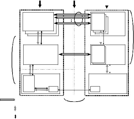
Figure 5-8 shows a more detailed view of Figure 5-2. The complete definition of the actual communication flows of Figure 5-2 supports the logical device and function layer communication flows. These actual communication flows cross several interface boundaries. Chapters 6 through 8 describe the mechanical, electrical, and protocol interface definitions of the USB “wire.” Chapter 9 describes the USB device programming interface that allows a USB device to be manipulated from the host side of the wire. Chapter 10 describes two host side software interfaces:
Host Controller Driver (HCD): The software interface between the USB Host Controller and USB System Software. This interface allows a range of Host Controller implementations without requiring all host software to be dependent on any particular implementation. One USB Driver can support different Host Controllers without requiring specific knowledge of a Host Controller implementation. A Host Controller implementer provides an HCD implementation that supports the Host Controller.
USB Driver (USBD): The interface between the USB System Software and the client software. This interface provides clients with convenient functions for manipulating USB devices.
Host |
Interconnect |
Physical Device |
||
|
|
|
|
|
|
|
|
|
|
Client SW |
Function |
|
a collection of |
||
Interface x |
||
manages an interface |
interfaces |
|
Pipe Bundle |
|
|
to an interface |
|
Buffers |
No USB |
Interface- |
No USB |
|
Format |
specific |
Format |
|
|
|
USB Logical |
USB System SW |
|
Endpoint |
Device |
|
|
||
manages devices |
|
Zero |
a collection of |
Default Pipe |
|
||
|
endpoints |
||
|
to Endpoint Zero |
|
|
USB Host
(Chapter 10)
Transfers |
USB |
Data Per |
USB |
|
Framed |
Endpoint |
Framed |
|
Data |
|
Data |
|
|
|
USB Bus |
USB Bus |
Host |
Interface |
Interface |
USB Framed |
|
|
Controller |
|
|
|
Data |
|
|
SIE |
SIE |
|
Transactions |
USB Wire |
Pipe: represents connection abstraction
between two horizontal entities
Mechanical,
Data transport mechanism |
Electrical, |
Protocol
USB-relevant format of transported data
(Chapter 6, 7, 8)
USB Device
(Chapter 9)
Figure 5-8. USB Host/Device Detailed View
31
Universal Serial Bus Specification Revision 1.1
A USB logical device appears to the USB system as a collection of endpoints. Endpoints are grouped into endpoint sets that implement an interface. Interfaces are views to the function. The USB System Software manages the device using the Default Control Pipe. Client software manages an interface using pipe bundles (associated with an endpoint set). Client software requests that data be moved across the USB between a buffer on the host and an endpoint on the USB device. The Host Controller (or USB device, depending on transfer direction) packetizes the data to move it over the USB. The Host Controller also coordinates when bus access is used to move the packet of data over the USB.
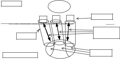
Figure 5-9 illustrates how communication flows are carried over pipes between endpoints and host side memory buffers. The following sections describe endpoints, pipes, and communication flows in more detail.
Host |
Client |
|
Software |
|
Buffers |
|
Communication |
Pipes |
Flows |
Endpoints
USB Logical Device
Interface
Figure 5-9. USB Communication Flow
Software on the host communicates with a logical device via a set of communication flows. The set of communication flows are selected by the device software/hardware designer(s) to efficiently match the communication requirements of the device to the transfer characteristics provided by the USB.
5.3.1 Device Endpoints
An endpoint is a uniquely identifiable portion of a USB device that is the terminus of a communication flow between the host and device. Each USB logical device is composed of a collection of independent endpoints. Each logical device has a unique address assigned by the system at device attachment time.
Each endpoint on a device is given at design time a unique device-determined identifier called the endpoint number. Each endpoint has a device-determined direction of data flow. The combination of the device address, endpoint number, and direction allows each endpoint to be uniquely referenced. Each endpoint is a simplex connection that supports data flow in one direction: either input (from device to host) or output (from host to device).
An endpoint has characteristics that determine the type of transfer service required between the endpoint and the client software. Endpoints describe themselves by:
Their bus access frequency/latency requirements
Their bandwidth requirements
Their endpoint number
The error handling behavior requirements
Maximum packet size that the endpoint is capable of sending or receiving
32
Universal Serial Bus Specification Revision 1.1
The transfer type for the endpoint (refer to Section 5.4 for details)
The direction data is transferred between the endpoint and the host.
Endpoints other than those with endpoint number zero are in an unknown state before being configured and may not be accessed by the host before being configured.
5.3.1.1 Endpoint Zero Requirements
All USB devices are required to implement a default control method that uses both the input and output endpoints with endpoint number zero. The USB System Software uses this default control method to initialize and generically manipulate the logical device (e.g., to configure the logical device) as the Default Control Pipe (see Section 5.3.2). The Default Control Pipe provides access to the device’s configuration information and allows generic USB status and control access. The Default Control Pipe supports control transfers as defined in Section 5.5. The endpoints with endpoint number zero are always accessible once a device is attached, powered, and has received a bus reset.
5.3.1.2 Non-endpoint Zero Requirements
Functions can have additional endpoints as required for their implementation. Low-speed functions are limited to two optional endpoints beyond the two required to implement the Default Control Pipe. Fullspeed devices can have additional endpoints only limited by the protocol definition (i.e., a maximum of 15 additional input endpoints and 15 additional output endpoints).
Endpoints other than those for the Default Control Pipe cannot be used until the device is configured as a normal part of the device configuration process (refer to Chapter 9).
5.3.2 Pipes
A USB pipe is an association between an endpoint on a device and software on the host. Pipes represent the ability to move data between software on the host via a memory buffer and an endpoint on a device. There are two different, mutually exclusive, pipe communication modes:
Stream: Data moving through a pipe has no USB-defined structure
Message: Data moving through a pipe has some USB-defined structure.
The USB does not interpret the content of data it delivers through a pipe. Even though a message pipe requires that data be structured according to USB definitions, the content of the data is not interpreted by the USB.
Additionally, pipes have the following associated with them:
A claim on USB bus access and bandwidth usage.
A transfer type.
The associated endpoint’s characteristics, such as directionality and maximum data payload sizes. The data payload is the data that is carried in the data field of a data packet within a bus transaction (as defined in Chapter 8).
The pipe that consists of the two endpoints with endpoint number zero is called the Default Control Pipe. This pipe is always available once a device is powered and has received a bus reset. Other pipes come into existence when a USB device is configured. The Default Control Pipe is used by the USB System Software to determine device identification and configuration requirements, and to configure the device. The Default Control Pipe can also be used by device-specific software after the device is configured. The USB System Software retains “ownership” of the Default Control Pipe and mediates use of the pipe by other client software.
33
Universal Serial Bus Specification Revision 1.1
A software client normally requests data transfers via I/O Request Packets (IRPs) to a pipe and then either waits or is notified when they are completed. Details about IRPs are defined in an operating systemspecific manner. This specification uses the term to simply refer to an identifiable request by a software client to move data between itself (on the host) and an endpoint of a device in an appropriate direction. A software client can cause a pipe to return all outstanding IRPs if it desires. The software client is notified that an IRP has completed when the bus transactions associated with it have completed either successfully or due to errors.
If there are no IRPs pending or in progress for a pipe, the pipe is idle and the Host Controller will take no action with regard to the pipe; i.e., the endpoint for such a pipe will not see any bus transactions directed to it. The only time bus activity is present for a pipe is when IRPs are pending for that pipe.
If a non-isochronous pipe encounters a condition that causes it to send a STALL to the host (refer to Chapter 8) or three bus errors are encountered on any packet of an IRP, the IRP is aborted/retired, all outstanding IRPs are also retired, and no further IRPs are accepted until the software client recovers from the condition (in an implementation-dependent way) and acknowledges the halt or error condition via a USBD call. An appropriate status informs the software client of the specific IRP result for error versus halt (refer to Chapter 10). Isochronous pipe behavior is described in Section 5.6.
An IRP may require multiple data payloads to move the client data over the bus. The data payloads for such a multiple data payload IRP are expected to be of the maximum packet size until the last data payload that contains the remainder of the overall IRP. See the description of each transfer type for more details. For such an IRP, short packets (i.e., less than maximum-sized data payloads) on input that do not completely fill an IRP data buffer can have one of two possible meanings, depending upon the expectations of a client:
A client can expect a variable-sized amount of data in an IRP. In this case, a short packet that does not fill an IRP data buffer can be used simply as an in-band delimiter to indicate “end of unit of data.”
The IRP should be retired without error and the Host Controller should advance to the next IRP.
A client can expect a specific-sized amount of data. In this case, a short packet that does not fill an IRP data buffer is an indication of an error. The IRP should be retired, the pipe should be stalled, and any pending IRPs associated with the pipe should also be retired.
Because the Host Controller must behave differently in the two cases and cannot know on its own which way to behave for a given IRP, it is possible to indicate per IRP which behavior the client desires.
An endpoint can inform the host that it is busy by responding with NAK. NAKs are not used as a retire condition for returning an IRP to a software client. Any number of NAKs can be encountered during the processing of a given IRP. A NAK response to a transaction does not constitute an error and is not counted as one of the three errors described above.
5.3.2.1 Stream Pipes
Stream pipes deliver data in the data packet portion of bus transactions with no USB-required structure on the data content. Data flows in at one end of a stream pipe and out the other end in the same order. Stream pipes are always uni-directional in their communication flow.
Data flowing through a stream pipe is expected to interact with what the USB believes is a single client. The USB System Software is not required to provide synchronization between multiple clients that may be using the same stream pipe. Data presented to a stream pipe is moved through the pipe in sequential order: first-in, first-out.
A stream pipe to a device is bound to a single device endpoint number in the appropriate direction (i.e., corresponding to an IN or OUT token as defined by the protocol layer). The device endpoint number for the opposite direction can be used for some other stream pipe to the device.
Stream pipes support bulk, isochronous, and interrupt transfer types, which are explained in later sections.
34