

Universal Serial Bus Specification Revision 1.1
6.5.4 Series “A” and Series “B” Plugs
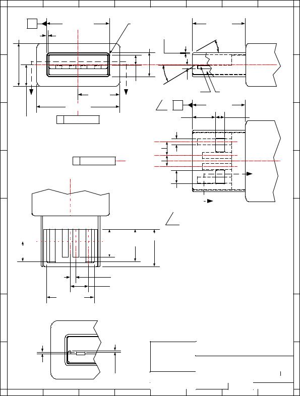
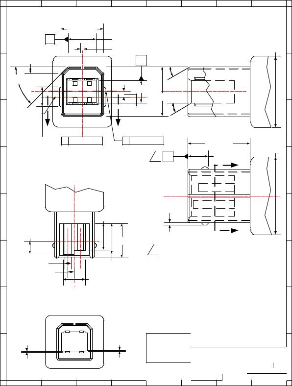
Electrical and mechanical interface configuration data for Series "A" and Series "B" plugs are shown in Figure 6-9 and Figure 6-10.
86
|
|
|
|
Universal Serial Bus Specification Revision 1.1 |
|
|
|
|||||
|
8 |
7 |
|
|
6 |
5 |
4 |
3 |
2 |
|
1 |
|
|
B |
|
12.00 ± 0.10 |
|
R 0.64 + 0.13 Typical |
|
11.75 MIN |
|
|
|
||
H |
8.0 MAX |
0.315 ± 0.03 Typical |
0.15 ± 0.10 Typical |
300 ± 20 Typical |
|
|
H |
|||||
|
|
|
|
|
|
4.50 ± 0.10 |
|
|
|
|
|
|
|
|
|
|
|
|
300 ± 20 |
|
|
|
|
|
|
|
|
4 |
3 |
2 |
1 |
|
|
|
|
|
|
|
G |
|
|
|
|
|
1.95 ± 0.05 |
0.38 ± 0.13 |
|
|
|
|
G |
|
|
|
|
|
|
|
|
|
|
|
||
|
A |
|
|
8.0 MAX |
A |
Plug Contact |
|
UL 94-V0 Plug Housing |
|
|||
|
|
|
|
|
A |
|
11.75 MIN |
|
|
|
||
|
|
|
16.0 MAX |
|
1 |
|
|
|
|
|||
|
4.0 MAX |
B |
Center Line |
5.16 ± 0.10 |
|
|
2.00 ± 0.13 (4) |
|
||||
|
|
|
|
|
|
|
|
|||||
F |
|
|
|
|
|
1.00 ± 0.05 (4) |
|
|
|
|
F |
|
|
|
|
|
|
|
2.50 ± 0.05 (2) |
|
|
|
|
Boot |
|
|
|
Section A - A |
|
2.00 ± 0.05 (2) |
|
|
|
|
Overmold |
|
||
|
|
|
B |
Center Line |
|
|
|
|
|
|
||
E |
|
|
|
|
|
|
|
|
|
B |
|
E |
|
|
|
|
|
|
|
|
|
|
|
||
|
|
|
|
|
|
2.50 ± 0.13 (4) |
|
|
|
|
|
|
|
|
|
|
|
|
|
Overmold |
|
|
|
Boot |
|
|
B |
||||||||||||||||||||||||||||||
|
|
|
|
|
|
|
|
|
|
|
|
|||||||||||||||||||||||||||||||||
|
|
|
|
|
|
|
|
|
|
1 |
Overall connector and cable assembly |
|||||||||||||||||||||||||||||||||
|
|
|
|
|
|
|
|
|
|
|
|
|
|
|
|
|
|
|
|
|
|
|
|
|
|
|
|
|
|
|
|
|
|
|
|
|
|
|
|
|
||||
|
|
|
|
|
|
|
|
|
|
|
|
|
|
|
|
|
|
|
|
|
|
|
|
|
|
|
|
|
|
|
|
|
|
|
|
|
|
|
|
|
||||
|
|
|
|
|
|
|
|
|
|
|
|
|
|
|
|
|
|
|
|
|
|
|
|
|
|
|
|
|
|
|
|
|
|
|
|
|
|
|
|
|
||||
|
|
|
|
|
|
|
|
|
|
|
|
|
|
|
|
|
|
|
|
|
|
|
|
|
|
|
|
|
|
|
|
|
|
|
|
|
|
|
|
|
||||
|
|
|
|
|
|
|
|
|
|
|
|
|
|
|
|
|
|
|
|
|
|
|
|
|
|
|
|
|
|
|
|
|
|
|
|
|
|
|
|
|
||||
D |
|
|
|
|
|
|
|
|
|
|
|
|
|
|
|
|
|
|
|
|
|
|
|
|
|
|
|
|
|
|
|
|
|
|
|
|
length is measured from Datum 'A' of D |
|||||||
|
|
|
|
|
|
|
|
|
|
|
|
|
|
|
|
|
|
|
|
|
|
|
|
|
|
|
|
|
|
|
|
|
|
|
|
|
||||||||
|
|
|
|
|
|
|
|
|
|
|
|
|
|
|
|
|
|
|
|
|
|
|
|
|
|
|
|
|
|
|
|
|
|
|
|
|
|
|
|
|
|
the Series "A" Plug to Datum 'A' of the |
||
|
|
|
|
|
|
|
|
|
|
|
|
|
|
|
|
|
|
|
|
|
|
|
|
|
|
|
|
|
|
|
|
|
|
|
|
|
|
|
|
|
|
|||
|
|
|
|
|
|
|
|
|
|
|
|
|
|
|
|
|
|
|
|
|
|
|
|
|
|
|
|
|
|
|
8.65 ± 0.19 |
|
S e r i e s " B " P l u g o r t o t h e b l u n t e n d |
|||||||||||
|
|
|
|
|
|
|
|
|
|
|
|
|
|
|
|
|
|
|
|
|
|
|
|
|
|
|
|
|
|
|
|
|
|
|
|
|
7.41 ± 0 |
.31 |
|
|
termination. |
|
||
|
|
|
|
|
|
|
|
|
|
|
|
|
|
|
|
|
|
|
|
|
|
|
|
|
|
|
|
|||||||||||||||||
|
|
|
|
|
|
|
|
|
|
|
|
|
|
|
|
|
|
|
|
|
|
|
|
|
|
|
|
|
|
|
|
|
|
|
|
|
|
|
|
|
|
|
||
4.2 MIN |
6.41 ± 0.31 |
GOLD PLATE AREA |
All dimensions are in millimeters m( m ) |
|
|
|
unless otherwise noted. |
C |
C |
|
1.0 ± 0.05 (2) |
|
3.5 ± 0.05 (2) |
|
9.70 ± 0.13 |
Section B - B
B |
B |
|
|
|
|
|
|
|
|
Interface Drawing |
|
|
A |
0.16 ± 0.15 |
|
|
|
|
|
USB Series "A" Plug |
|||
|
|
|
|
|
|
|
|
|
A |
|
|
|
|
|
0.13 ± 0.13 |
|
SIZE |
|
DATE |
DRAWING NUMBER |
REV |
|
|
|
|
|
A |
|
2/98 |
N/A |
C |
|
|
|
|
|
|
|
|
||||
|
|
|
|
|
|
SCALE: |
N/A |
SHEET |
1 of 1 |
|
|
8 |
7 |
6 |
5 |
4 |
3 |
|
|
2 |
1 |
Figure 6-9. USB Series "A" Plug Interface Drawing
87
|
|
|
|
Universal Serial Bus Specification Revision 1.1 |
|
|
|
||||||
|
8 |
7 |
|
6 |
|
5 |
|
4 |
|
3 |
2 |
1 |
|
H |
|
|
8.00 ± 0.10 |
|
|
|
|
|
|
|
|
H |
|
|
|
|
|
|
|
|
|
|
|
|
|
||
|
C |
|
|
|
5.83 ± 0.10 |
|
|
|
|
|
|
|
|
|
|
|
|
|
0.38 MAX |
|
|
|
|
|
10.5 MAX |
|
|
|
1.46 ± 0.10 |
|
|
|
|
B |
300 |
± 20 |
Typical |
|
|
|
|
G |
450 ± 0.50 (2) |
|
1 |
2 |
|
|
|
|
|
|
|
Boot |
G |
|
|
|
|
|
|
|
|
|
|||||
|
|
|
0.80 ± 0.05 |
|
|
|
|
Overmold |
|
||||
|
|
|
|
|
|
3.29 ± 0.05 |
|
|
|
|
|
|
|
|
|
|
4 |
3 |
|
|
7.26 ± 0.10 |
|
|
|
|
||
|
|
|
|
|
|
|
|
|
|
|
|
||
|
Center Line |
|
|
|
|
|
|
|
|
|
|
|
|
F |
of 2.85 |
|
|
|
|
|
|
300 ± 2 |
0 (2) |
|
|
F |
|
A |
|
|
|
A |
|
|
|
|
|
|
|
||
|
|
|
|
|
|
|
|
|
|
|
|
||
|
2.85 ± 0.13 (2) |
C |
Center Line |
B |
Center Line |
|
|
11.75 MIN |
|
|
|
||
|
|
|
|
|
|
|
|
|
|
|
11.5 MAX |
|
|
|
|
|
|
|
|
|
|
|
|
|
|
|
|
|
|
|
|
|
|
|
1 |
|
A |
3.70 ± 0.13 |
|
|
|
|
|
|
|
|
|
|
|
|
|
B |
|
|
|
|
|
|
|
|
|
|
|
|
|
|
|
|
|
E |
|
Section A - A |
|
|
|
|
|
|
|
Boot |
E |
||
|
|
|
|
|
|
|
|
|
|
||||
|
|
|
|
|
|
|
|
|
|
|
|
|
|
|
|
|
|
|
|
|
0.25 ± 0.05 |
|
Overmold |
|
|||
|
|
|
|
|
|
|
|
|
|
||||
D |
|
|
|
6.41 ± 0.31 |
|
|
|
|
|
|
|
D |
|
|
|
|
|
|
|
|
|
|
|
|
|
||
|
4.20 MIN |
|
|
|
|
|
|
|
|
|
B |
|
|
|
Gold Plate Area |
|
|
|
|
|
|
|
|
|
|
|
|
|
|
|
|
8.65 ± 0.19 |
|
|
|
|
|
|
|
||
|
|
|
|
|
|
Overall connector and cable assembly length |
|
||||||
|
|
|
|
|
|
|
1 |
|
|||||
|
|
|
|
|
|
|
is measured from Datum 'A' of the Series "B" |
|
|||||
|
|
|
|
|
|
|
|
|
|||||
|
1.16 MAX |
|
|
7.41 ± 0.31 |
|
|
Plug to Datum 'A' of the Series "A" Plug or |
|
|||||
C |
|
|
|
|
the blunt end termination. |
|
|
C |
|||||
|
|
|
|
|
|
|
|
|
|||||
|
1.25 ± 0.10 (4) |
|
|
|
|
|
|
|
|
|
|||
|
|
|
4.67 ± 0.10 |
|
|
|
|
|
|
|
|
||
|
|
|
|
|
|
|
|
|
|
|
|
||
|
|
|
|
All dimensions are in millimeters (m m ) |
|
C |
Center Line |
||||
unless otherwise noted. |
|||||
|
|
|
|
||
|
|
|
|
||
|
Section B - B |
B |
B |
0.16 ± 0.15 |
|
|
0.13 ± 0.13 |
|
|
Interface Drawing |
|
|
Typical |
|
|
Typical |
|
|
|
||
A |
|
|
|
|
USB Series "B" Plug |
|||
|
|
|
|
|
|
|
A |
|
|
|
|
|
|
SIZE |
DATE |
DRAWING NUMBER |
REV |
|
|
|
|
|
A |
2/98 |
N/A |
C |
|
|
|
|
|
SCALE: |
N/A |
SHEET |
1 of 1 |
8 |
7 |
6 |
5 |
4 |
3 |
|
2 |
1 |
Figure 6-10. USB Series “B” Plug Interface Drawing
88
Universal Serial Bus Specification Revision 1.1
6.5.4.1Plug Injection Molded Thermoplastic Insulator Material
Minimum UL 94-V0 rated, thirty percent (30%) glass-filled polybutylene terephthalate (PBT) or polyethylene terephthalate (PET) or better.
Typical Colors: Black, Gray and Natural.
Flammability Characteristics: UL 94-V0 rated.
Flame Retardant Package must meet or exceed the requirements for UL, CSA and VDE.
Oxygen Index (LOI): 21%. ASTM D 2863.
6.5.4.2Plug Shell Materials
Substrate Material: 0.30 + 0.05 mm phosphor bronze, nickel silver or other suitable material.
Plating:
A.Underplate: Optional. Minimum 1.00 micrometers (40 microinches) nickel. In addition, manufacturer may use a copper underplate beneath the nickel.
B.Outside: Minimum 2.5 micrometers (100 microinches) bright tin or bright tin-lead.
6.5.4.3Plug (Male) Contact M aterials
Substrate Material. 0.30 + 0.05 mm half-hard phosphor bronze.
Plating. Contacts are to be selectively plated.
A.Option I
1.Underplate: Minimum 1.25 micrometers (50 microinches) nickel. Copper over base material is optional.
2.Mating Area: Minimum 0.05 micrometers (2 microinches) gold over a minimum of 0.70 micrometers (28 microinches) palladium.
3.Solder Tails: Minimum 3.8 micrometers (150 microinches) bright tin-lead over the underplate.
B.Option II
1.Underplate: Minimum 1.25 micrometers (50 microinches) nickel. Copper over base material is optional.
2.Mating Area: Minimum 0.05 micrometers (2 microinches) gold over a minimum of 0.75 micrometers (30 microinches) palladium-nickel.
3.Wire Crimp/Solder Tails: Minimum 3.8 micrometers (150 microinches) bright tin-lead over the underplate.
C.Option III
1.Underplate: Minimum 1.25 micrometers (50 microinches) nickel. Copper over base material is optional.
2.Mating Area: Minimum 0.75 micrometers (30 microinches) gold.
3.Solder Tails: Minimum 3.8 micrometers (150 microinches) bright tin-lead over the underplate.
89