

- •Chapter 1
- •1.1 Motivation
- •1.2 Objective of the Specification
- •1.3 Scope of the Document
- •1.4 Document Organization
- •Chapter 2
- •Chapter 3
- •3.1 Goals for the Universal Serial Bus
- •3.2 Taxonomy of Application Space
- •3.3 Feature List
- •Chapter 4
- •4.1 USB System Description
- •4.1.1 Bus Topology
- •4.2 Physical Interface
- •4.2.1 Electrical
- •4.2.2 Mechanical
- •4.3 Power
- •4.3.1 Power Distribution
- •4.3.2 Power Management
- •4.4 Bus Protocol
- •4.5 Robustness
- •4.5.1 Error Detection
- •4.5.2 Error Handling
- •4.6 System Configuration
- •4.6.1 Attachment of USB Devices
- •4.6.2 Removal of USB Devices
- •4.6.3 Bus Enumeration
- •4.7 Data Flow Types
- •4.7.1 Control Transfers
- •4.7.2 Bulk Transfers
- •4.7.3 Interrupt Transfers
- •4.7.4 Isochronous Transfers
- •4.7.5 Allocating USB Bandwidth
- •4.8 USB Devices
- •4.8.1 Device Characterizations
- •4.8.2 Device Descriptions
- •4.9 USB Host: Hardware and Software
- •4.10 Architectural Extensions
- •Chapter 5
- •5.1 Implementer Viewpoints
- •5.2 Bus Topology
- •5.2.1 USB Host
- •5.2.2 USB Devices
- •5.2.3 Physical Bus Topology
- •5.2.4 Logical Bus Topology
- •5.2.5 Client Software-to-function Relationship
- •5.3 USB Communication Flow
- •5.3.1 Device Endpoints
- •5.3.2 Pipes
- •5.4 Transfer Types
- •5.5 Control Transfers
- •5.5.1 Control Transfer Data Format
- •5.5.2 Control Transfer Direction
- •5.5.3 Control Transfer Packet Size Constraints
- •5.5.4 Control Transfer Bus Access Constraints
- •5.5.5 Control Transfer Data Sequences
- •5.6 Isochronous Transfers
- •5.6.1 Isochronous Transfer Data Format
- •5.6.2 Isochronous Transfer Direction
- •5.6.3 Isochronous Transfer Packet Size Constraints
- •5.6.4 Isochronous Transfer Bus Access Constraints
- •5.6.5 Isochronous Transfer Data Sequences
- •5.7 Interrupt Transfers
- •5.7.1 Interrupt Transfer Data Format
- •5.7.2 Interrupt Transfer Direction
- •5.7.3 Interrupt Transfer Packet Size Constraints
- •5.7.4 Interrupt Transfer Bus Access Constraints
- •5.7.5 Interrupt Transfer Data Sequences
- •5.8 Bulk Transfers
- •5.8.1 Bulk Transfer Data Format
- •5.8.2 Bulk Transfer Direction
- •5.8.3 Bulk Transfer Packet Size Constraints
- •5.8.4 Bulk Transfer Bus Access Constraints
- •5.8.5 Bulk Transfer Data Sequences
- •5.9 Bus Access for Transfers
- •5.9.1 Transfer Management
- •5.9.2 Transaction Tracking
- •5.9.3 Calculating Bus Transaction Times
- •5.9.4 Calculating Buffer Sizes in Functions and Software
- •5.9.5 Bus Bandwidth Reclamation
- •5.10 Special Considerations for Isochronous Transfers
- •5.10.1 Example Non-USB Isochronous Application
- •5.10.2 USB Clock Model
- •5.10.3 Clock Synchronization
- •5.10.4 Isochronous Devices
- •5.10.5 Data Prebuffering
- •5.10.6 SOF Tracking
- •5.10.7 Error Handling
- •5.10.8 Buffering for Rate Matching
- •Chapter 6
- •6.1 Architectural Overview
- •6.3 Cable
- •6.4 Cable Assembly
- •6.4.1 Detachable Cable Assemblies
- •6.4.3 Low-speed Captive Cable Assemblies
- •6.4.4 Prohibited Cable Assemblies
- •6.5.1 USB Icon Location
- •6.5.2 USB Connector Termination Data
- •6.5.3 Series “A” and Series “B” Receptacles
- •6.5.4 Series “A” and Series “B” Plugs
- •6.6.1 Description
- •6.6.2 Construction
- •6.6.3 Electrical Characteristics
- •6.6.4 Cable Environmental Characteristics
- •6.6.5 Listing
- •6.7 Electrical, Mechanical and Environmental Compliance Standards
- •6.7.1 Applicable Documents
- •6.8 USB Grounding
- •Chapter 7
- •7.1 Signaling
- •7.1.1 USB Driver Characteristics
- •7.1.2 Data Signal Rise and Fall
- •7.1.3 Cable Skew
- •7.1.4 Receiver Characteristics
- •7.1.5 Device Speed Identification
- •7.1.6 Input Characteristics
- •7.1.7 Signaling Levels
- •7.1.8 Data Encoding/Decoding
- •7.1.9 Bit Stuffing
- •7.1.10 Sync Pattern
- •7.1.11 Data Signaling Rate
- •7.1.12 Frame Interval and Frame Interval Adjustment
- •7.1.13 Data Source Signaling
- •7.1.14 Hub Signaling Timings
- •7.1.15 Receiver Data Jitter
- •7.1.16 Cable Delay
- •7.1.17 Cable Attenuation
- •7.1.18 Bus Turn-around Time and Inter-packet Delay
- •7.1.19 Maximum End-to-end Signal Delay
- •7.2 Power Distribution
- •7.2.1 Classes of Devices
- •7.2.2 Voltage Drop Budget
- •7.2.3 Power Control During Suspend/Resume
- •7.2.4 Dynamic Attach and Detach
- •7.3 Physical Layer
- •7.3.1 Regulatory Requirements
- •7.3.2 Bus Timing/Electrical Characteristics
- •7.3.3 Timing Waveforms
- •Chapter 8
- •8.1 Bit Ordering
- •8.2 SYNC Field
- •8.3 Packet Field Formats
- •8.3.1 Packet Identifier Field
- •8.3.2 Address Fields
- •8.3.3 Frame Number Field
- •8.3.4 Data Field
- •8.3.5 Cyclic Redundancy Checks
- •8.4 Packet Formats
- •8.4.1 Token Packets
- •8.4.2 Start-of-Frame Packets
- •8.4.3 Data Packets
- •8.4.4 Handshake Packets
- •8.4.5 Handshake Responses
- •8.5 Transaction Formats
- •8.5.1 Bulk Transactions
- •8.5.2 Control Transfers
- •8.5.3 Interrupt Transactions
- •8.5.4 Isochronous Transactions
- •8.6 Data Toggle Synchronization and Retry
- •8.6.1 Initialization via SETUP Token
- •8.6.2 Successful Data Transactions
- •8.6.3 Data Corrupted or Not Accepted
- •8.6.4 Corrupted ACK Handshake
- •8.6.5 Low-speed Transactions
- •8.7 Error Detection and Recovery
- •8.7.1 Packet Error Categories
- •8.7.2 Bus Turn-around Timing
- •8.7.3 False EOPs
- •8.7.4 Babble and Loss of Activity Recovery
- •Chapter 9
- •9.1 USB Device States
- •9.1.1 Visible Device States
- •9.1.2 Bus Enumeration
- •9.2 Generic USB Device Operations
- •9.2.1 Dynamic Attachment and Removal
- •9.2.2 Address Assignment
- •9.2.3 Configuration
- •9.2.4 Data Transfer
- •9.2.5 Power Management
- •9.2.6 Request Processing
- •9.2.7 Request Error
- •9.3 USB Device Requests
- •9.3.1 bmRequestType
- •9.3.2 bRequest
- •9.3.3 wValue
- •9.3.4 wIndex
- •9.3.5 wLength
- •9.4 Standard Device Requests
- •9.4.1 Clear Feature
- •9.4.2 Get Configuration
- •9.4.3 Get Descriptor
- •9.4.4 Get Interface
- •9.4.5 Get Status
- •9.4.6 Set Address
- •9.4.7 Set Configuration
- •9.4.8 Set Descriptor
- •9.4.9 Set Feature
- •9.4.10 Set Interface
- •9.4.11 Synch Frame
- •9.5 Descriptors
- •9.6 Standard USB Descriptor Definitions
- •9.6.1 Device
- •9.6.2 Configuration
- •9.6.3 Interface
- •9.6.4 Endpoint
- •9.6.5 String
- •9.7 Device Class Definitions
- •9.7.1 Descriptors
- •9.7.2 Interface(s) and Endpoint Usage
- •9.7.3 Requests
- •Chapter 10
- •10.1 Overview of the USB Host
- •10.1.1 Overview
- •10.1.2 Control Mechanisms
- •10.1.3 Data Flow
- •10.1.4 Collecting Status and Activity Statistics
- •10.1.5 Electrical Interface Considerations
- •10.2 Host Controller Requirements
- •10.2.1 State Handling
- •10.2.2 Serializer/Deserializer
- •10.2.3 Frame Generation
- •10.2.4 Data Processing
- •10.2.5 Protocol Engine
- •10.2.6 Transmission Error Handling
- •10.2.7 Remote Wakeup
- •10.2.8 Root Hub
- •10.2.9 Host System Interface
- •10.3 Overview of Software Mechanisms
- •10.3.1 Device Configuration
- •10.3.2 Resource Management
- •10.3.3 Data Transfers
- •10.3.4 Common Data Definitions
- •10.4 Host Controller Driver
- •10.5 Universal Serial Bus Driver
- •10.5.1 USBD Overview
- •10.5.2 USBD Command Mechanism Requirements
- •10.5.3 USBD Pipe Mechanisms
- •10.5.4 Managing the USB via the USBD Mechanisms
- •10.5.5 Passing USB Preboot Control to the Operating System
- •10.6 Operating System Environment Guides
- •Chapter 11
- •11.1 Overview
- •11.1.1 Hub Architecture
- •11.1.2 Hub Connectivity
- •11.2 Hub Frame Timer
- •11.2.1 Frame Timer Synchronization
- •11.2.2 EOF1 and EOF2 Timing Points
- •11.3 Host Behavior at End-of-Frame
- •11.3.1 Latest Host Packet
- •11.3.2 Packet Nullification
- •11.3.3 Transaction Completion Prediction
- •11.4 Internal Port
- •11.4.1 Inactive
- •11.4.2 Suspend Delay
- •11.4.3 Full Suspend (Fsus)
- •11.4.4 Generate Resume (GResume)
- •11.5 Downstream Ports
- •11.5.1 Downstream Port State Descriptions
- •11.6 Upstream Port
- •11.6.1 Receiver
- •11.6.2 Transmitter
- •11.7 Hub Repeater
- •11.7.1 Wait for Start of Packet from Upstream Port (WFSOPFU)
- •11.7.2 Wait for End of Packet from Upstream Port (WFEOPFU)
- •11.7.3 Wait for Start of Packet (WFSOP)
- •11.7.4 Wait for End of Packet (WFEOP)
- •11.8 Bus State Evaluation
- •11.8.1 Port Error
- •11.8.2 Speed Detection
- •11.8.3 Collision
- •11.9 Suspend and Resume
- •11.10 Hub Reset Behavior
- •11.10.1 Hub Receiving Reset on Upstream Port
- •11.11 Hub Port Power Control
- •11.11.1 Multiple Gangs
- •11.12 Hub I/O Buffer Requirements
- •11.12.1 Pull-up and Pull-down Resistors
- •11.12.2 Edge Rate Control
- •11.13 Hub Controller
- •11.13.1 Endpoint Organization
- •11.13.2 Hub Information Architecture and Operation
- •11.13.3 Port Change Information Processing
- •11.13.4 Hub and Port Status Change Bitmap
- •11.13.5 Over-current Reporting and Recovery
- •11.14 Hub Configuration
- •11.15 Descriptors
- •11.15.1 Standard Descriptors
- •11.15.2 Class-specific Descriptors
- •11.16 Requests
- •11.16.1 Standard Requests
- •11.16.2 Class-specific Requests
- •Index
Universal Serial Bus Specification Revision 1.1
Chapter 10
USB Host: Hardware and Software
The USB interconnect supports data traffic between a host and a USB device. This chapter describes the host interfaces necessary to facilitate USB communication between a software client, resident on the host, and a function implemented on a device. The implementation described in this chapter is not required. This implementation is provided as an example to illustrate the host system behavior expected by a USB device. A host system may provide a different host software implementation as long as a USB device experiences the shame host behavior.
10.1 Overview of the USB Host
10.1.1 Overview
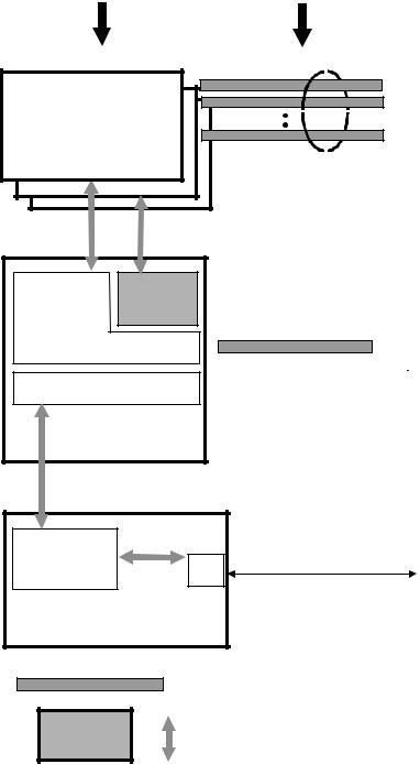
The basic flow and interrelationships of the USB communications model are shown in Figure 10-1
Host |
Interconnect |
Device |
Client
USB System
USB Bus
Interface
Function
USB Device
USB Bus
Interface
Actual communications flow
Logical communications flow
Figure 10-1. Interlayer Communications Model
The host and the device are divided into the distinct layers depicted in Figure 10-1. Vertical arrows indicate the actual communication on the host. The corresponding interfaces on the device are implementation-specific. All communications between the host and device ultimately occur on the physical USB wire. However, there are logical host-device interfaces between each horizontal layer. These communications, between client software resident on the host and the function provided by the device, are typified by a contract based on the needs of the application currently using the device and the capabilities provided by the device.
This client-function interaction creates the requirements for all of the underlying layers and their interfaces.
207
Universal Serial Bus Specification Revision 1.1
This chapter describes this model from the point of view of the host and its layers. Figure 10-2 describes, based on the overall view introduced in Chapter 5, the host’s view of its communication with the device.
Host
Client
manages interfaces
Interconnect
Pipe Bundle
to an interface
IRPs |
Configuration |
|
USB Driver |
Host |
|
Software |
|
|
|
|
|
HC Driver |
|
Default Pipe |
|
|
|
|
|
to Endpoint Zero |
USB System |
|
|
manages pipes |
|
|
HW-Defined |
|
|
Host |
|
|
Controller |
HC- |
SIE |
|
Defined |
USB Wire |
USB Bus |
|
|
|
|
|
Interface |
|
|
|
|
Pipe: Represents connection |
|
|
abstraction between two horizontal |
|
|
layers |
Optional |
|
|
Component |
|
Interprocess Communication |
Figure 10-2. Host Communications
208
Universal Serial Bus Specification Revision 1.1
There is only one host for each USB. The major layers of a host consist of the following:
USB bus interface
USB System
Client.
The USB bus interface handles interactions for the electrical and protocol layers (refer to Chapter 7 and Chapter 8). From the interconnect point of view, a similar USB bus interface is provided by both the USB device and the host, as exemplified by the Serial Interface Engine (SIE). On the host, however, the USB bus interface has additional responsibilities due to the unique role of the host on the USB and is implemented as the Host Controller. The Host Controller has an integrated root hub providing attachment points to the USB wire.
The USB System uses the Host Controller to manage data transfers between the host and USB devices. The interface between the USB System and the Host Controller is dependent on the hardware definition of the Host Controller. The USB System, in concert with the Host Controller, performs the translation between the client’s view of data transfers and the USB transactions appearing on the interconnect. This includes the addition of any USB feature support such as protocol wrappers. The USB System is also responsible for managing USB resources, such as bandwidth and bus power, so that client access to the USB is possible.
The USB System has three basic components:
Host Controller Driver
USB Driver
Host Software.
The Host Controller Driver (HCD) exists to more easily map the various Host Controller implementations into the USB System, such that a client can interact with its device without knowing to which Host Controller the device is connected. The USB Driver (USBD) provides the basic host interface (USBDI) for clients to USB devices. The interface between the HCD and the USBD is known as the Host Controller Driver Interface (HCDI). This interface is never available directly to clients and thus is not defined by the USB Specification. A particular HCDI is, however, defined by each operating system that supports various Host Controller implementations.
The USBD provides data transfer mechanisms in the form of I/O Request Packets (IRPs), which consist of a request to transport data across a specific pipe. In addition to providing data transfer mechanisms, the USBD is responsible for presenting to its clients an abstraction of a USB device that can be manipulated for configuration and state management. As part of this abstraction, the USBD owns the default pipe (see Chapter 5 and Chapter 9) through which all USB devices are accessed for the purposes of standard USB control. This default pipe represents a logical communication between the USBD and the abstraction of a USB device as shown in Figure 10-2.
In some operating systems, additional non-USB System Software is available that provides configuration and loading mechanisms to device drivers. In such operating systems, the device driver shall use the provided interfaces instead of directly accessing the USBDI mechanisms.
The client layer describes all the software entities that are responsible for directly interacting with USB devices. When each device is attached to the system, these clients might interact directly with the peripheral hardware. The shared characteristics of the USB place USB System Software between the client and its device; that is, a client cannot directly access the device’s hardware.
209
Universal Serial Bus Specification Revision 1.1
Overall, the host layers provide the following capabilities:
Detecting the attachment and removal of USB devices
Managing USB standard control flow between the host and USB devices
Managing data flow between the host and USB devices
Collecting status and activity statistics
Controlling the electrical interface between the Host Controller and USB devices, including the provision of a limited amount of power.
The following sections describe these responsibilities and the requirements placed on the USBDI in greater detail. The actual interfaces used for a specific combination of host platform and operating system are described in the appropriate operating system environment guide.
All hubs (see Chapter 11) report internal status changes and their port change status via the status change pipe. This includes a notification of when a USB device is attached to or removed from one of their ports. A USBD client generically known as the hub driver receives these notifications as owner of the hub’s Status Change pipe. For device attachments, the hub driver then initiates the device configuration process. In some systems, this hub driver is a part of the host software provided by the operating system for managing devices.
10.1.2 Control Mechanisms
Control information may be passed between the host and a USB device using in-band or out-of-band signaling. In-band signaling mixes control information with data in a pipe outside the awareness of the host. Out-of-band signaling places control information in a separate pipe.
There is a message pipe called the default pipe for each attached USB device. This logical association between a host and a USB device is used for USB standard control flow such as device enumeration and configuration. The default pipe provides a standard interface to all USB devices. The default pipe may also be used for device-specific communications, as mediated by the USBD, which owns the default pipes of all of the USB devices.
A particular USB device may allow the use of additional message pipes to transfer device-specific control information. These pipes use the same communications protocol as the default pipe, but the information transferred is specific to the USB device and is not standardized by the USB Specification.
The USBD supports the sharing of the default pipe, which it owns and uses, with its clients. It also provides access to any other control pipes associated with the device.
10.1.3 Data Flow
The Host Controller is responsible for transferring streams of data between the host and USB devices. These data transfers are treated as a continuous stream of bytes. The USB supports four basic types of data transfers:
Control transfers
Isochronous transfers
Interrupt transfers
Bulk transfers.
For additional information on transfer types, refer to Chapter 5.
Each device presents one or more interfaces that a client may use to communicate with the device. Each interface is composed of zero or more pipes that individually transfer data between the client and a particular endpoint on the device. The USBD establishes interfaces and pipes at the explicit request of the Host Software. The Host Controller provides service based on parameters provided by the Host Software when the configuration request is made.
210