

- •Chapter 1
- •1.1 Motivation
- •1.2 Objective of the Specification
- •1.3 Scope of the Document
- •1.4 Document Organization
- •Chapter 2
- •Chapter 3
- •3.1 Goals for the Universal Serial Bus
- •3.2 Taxonomy of Application Space
- •3.3 Feature List
- •Chapter 4
- •4.1 USB System Description
- •4.1.1 Bus Topology
- •4.2 Physical Interface
- •4.2.1 Electrical
- •4.2.2 Mechanical
- •4.3 Power
- •4.3.1 Power Distribution
- •4.3.2 Power Management
- •4.4 Bus Protocol
- •4.5 Robustness
- •4.5.1 Error Detection
- •4.5.2 Error Handling
- •4.6 System Configuration
- •4.6.1 Attachment of USB Devices
- •4.6.2 Removal of USB Devices
- •4.6.3 Bus Enumeration
- •4.7 Data Flow Types
- •4.7.1 Control Transfers
- •4.7.2 Bulk Transfers
- •4.7.3 Interrupt Transfers
- •4.7.4 Isochronous Transfers
- •4.7.5 Allocating USB Bandwidth
- •4.8 USB Devices
- •4.8.1 Device Characterizations
- •4.8.2 Device Descriptions
- •4.9 USB Host: Hardware and Software
- •4.10 Architectural Extensions
- •Chapter 5
- •5.1 Implementer Viewpoints
- •5.2 Bus Topology
- •5.2.1 USB Host
- •5.2.2 USB Devices
- •5.2.3 Physical Bus Topology
- •5.2.4 Logical Bus Topology
- •5.2.5 Client Software-to-function Relationship
- •5.3 USB Communication Flow
- •5.3.1 Device Endpoints
- •5.3.2 Pipes
- •5.4 Transfer Types
- •5.5 Control Transfers
- •5.5.1 Control Transfer Data Format
- •5.5.2 Control Transfer Direction
- •5.5.3 Control Transfer Packet Size Constraints
- •5.5.4 Control Transfer Bus Access Constraints
- •5.5.5 Control Transfer Data Sequences
- •5.6 Isochronous Transfers
- •5.6.1 Isochronous Transfer Data Format
- •5.6.2 Isochronous Transfer Direction
- •5.6.3 Isochronous Transfer Packet Size Constraints
- •5.6.4 Isochronous Transfer Bus Access Constraints
- •5.6.5 Isochronous Transfer Data Sequences
- •5.7 Interrupt Transfers
- •5.7.1 Interrupt Transfer Data Format
- •5.7.2 Interrupt Transfer Direction
- •5.7.3 Interrupt Transfer Packet Size Constraints
- •5.7.4 Interrupt Transfer Bus Access Constraints
- •5.7.5 Interrupt Transfer Data Sequences
- •5.8 Bulk Transfers
- •5.8.1 Bulk Transfer Data Format
- •5.8.2 Bulk Transfer Direction
- •5.8.3 Bulk Transfer Packet Size Constraints
- •5.8.4 Bulk Transfer Bus Access Constraints
- •5.8.5 Bulk Transfer Data Sequences
- •5.9 Bus Access for Transfers
- •5.9.1 Transfer Management
- •5.9.2 Transaction Tracking
- •5.9.3 Calculating Bus Transaction Times
- •5.9.4 Calculating Buffer Sizes in Functions and Software
- •5.9.5 Bus Bandwidth Reclamation
- •5.10 Special Considerations for Isochronous Transfers
- •5.10.1 Example Non-USB Isochronous Application
- •5.10.2 USB Clock Model
- •5.10.3 Clock Synchronization
- •5.10.4 Isochronous Devices
- •5.10.5 Data Prebuffering
- •5.10.6 SOF Tracking
- •5.10.7 Error Handling
- •5.10.8 Buffering for Rate Matching
- •Chapter 6
- •6.1 Architectural Overview
- •6.3 Cable
- •6.4 Cable Assembly
- •6.4.1 Detachable Cable Assemblies
- •6.4.3 Low-speed Captive Cable Assemblies
- •6.4.4 Prohibited Cable Assemblies
- •6.5.1 USB Icon Location
- •6.5.2 USB Connector Termination Data
- •6.5.3 Series “A” and Series “B” Receptacles
- •6.5.4 Series “A” and Series “B” Plugs
- •6.6.1 Description
- •6.6.2 Construction
- •6.6.3 Electrical Characteristics
- •6.6.4 Cable Environmental Characteristics
- •6.6.5 Listing
- •6.7 Electrical, Mechanical and Environmental Compliance Standards
- •6.7.1 Applicable Documents
- •6.8 USB Grounding
- •Chapter 7
- •7.1 Signaling
- •7.1.1 USB Driver Characteristics
- •7.1.2 Data Signal Rise and Fall
- •7.1.3 Cable Skew
- •7.1.4 Receiver Characteristics
- •7.1.5 Device Speed Identification
- •7.1.6 Input Characteristics
- •7.1.7 Signaling Levels
- •7.1.8 Data Encoding/Decoding
- •7.1.9 Bit Stuffing
- •7.1.10 Sync Pattern
- •7.1.11 Data Signaling Rate
- •7.1.12 Frame Interval and Frame Interval Adjustment
- •7.1.13 Data Source Signaling
- •7.1.14 Hub Signaling Timings
- •7.1.15 Receiver Data Jitter
- •7.1.16 Cable Delay
- •7.1.17 Cable Attenuation
- •7.1.18 Bus Turn-around Time and Inter-packet Delay
- •7.1.19 Maximum End-to-end Signal Delay
- •7.2 Power Distribution
- •7.2.1 Classes of Devices
- •7.2.2 Voltage Drop Budget
- •7.2.3 Power Control During Suspend/Resume
- •7.2.4 Dynamic Attach and Detach
- •7.3 Physical Layer
- •7.3.1 Regulatory Requirements
- •7.3.2 Bus Timing/Electrical Characteristics
- •7.3.3 Timing Waveforms
- •Chapter 8
- •8.1 Bit Ordering
- •8.2 SYNC Field
- •8.3 Packet Field Formats
- •8.3.1 Packet Identifier Field
- •8.3.2 Address Fields
- •8.3.3 Frame Number Field
- •8.3.4 Data Field
- •8.3.5 Cyclic Redundancy Checks
- •8.4 Packet Formats
- •8.4.1 Token Packets
- •8.4.2 Start-of-Frame Packets
- •8.4.3 Data Packets
- •8.4.4 Handshake Packets
- •8.4.5 Handshake Responses
- •8.5 Transaction Formats
- •8.5.1 Bulk Transactions
- •8.5.2 Control Transfers
- •8.5.3 Interrupt Transactions
- •8.5.4 Isochronous Transactions
- •8.6 Data Toggle Synchronization and Retry
- •8.6.1 Initialization via SETUP Token
- •8.6.2 Successful Data Transactions
- •8.6.3 Data Corrupted or Not Accepted
- •8.6.4 Corrupted ACK Handshake
- •8.6.5 Low-speed Transactions
- •8.7 Error Detection and Recovery
- •8.7.1 Packet Error Categories
- •8.7.2 Bus Turn-around Timing
- •8.7.3 False EOPs
- •8.7.4 Babble and Loss of Activity Recovery
- •Chapter 9
- •9.1 USB Device States
- •9.1.1 Visible Device States
- •9.1.2 Bus Enumeration
- •9.2 Generic USB Device Operations
- •9.2.1 Dynamic Attachment and Removal
- •9.2.2 Address Assignment
- •9.2.3 Configuration
- •9.2.4 Data Transfer
- •9.2.5 Power Management
- •9.2.6 Request Processing
- •9.2.7 Request Error
- •9.3 USB Device Requests
- •9.3.1 bmRequestType
- •9.3.2 bRequest
- •9.3.3 wValue
- •9.3.4 wIndex
- •9.3.5 wLength
- •9.4 Standard Device Requests
- •9.4.1 Clear Feature
- •9.4.2 Get Configuration
- •9.4.3 Get Descriptor
- •9.4.4 Get Interface
- •9.4.5 Get Status
- •9.4.6 Set Address
- •9.4.7 Set Configuration
- •9.4.8 Set Descriptor
- •9.4.9 Set Feature
- •9.4.10 Set Interface
- •9.4.11 Synch Frame
- •9.5 Descriptors
- •9.6 Standard USB Descriptor Definitions
- •9.6.1 Device
- •9.6.2 Configuration
- •9.6.3 Interface
- •9.6.4 Endpoint
- •9.6.5 String
- •9.7 Device Class Definitions
- •9.7.1 Descriptors
- •9.7.2 Interface(s) and Endpoint Usage
- •9.7.3 Requests
- •Chapter 10
- •10.1 Overview of the USB Host
- •10.1.1 Overview
- •10.1.2 Control Mechanisms
- •10.1.3 Data Flow
- •10.1.4 Collecting Status and Activity Statistics
- •10.1.5 Electrical Interface Considerations
- •10.2 Host Controller Requirements
- •10.2.1 State Handling
- •10.2.2 Serializer/Deserializer
- •10.2.3 Frame Generation
- •10.2.4 Data Processing
- •10.2.5 Protocol Engine
- •10.2.6 Transmission Error Handling
- •10.2.7 Remote Wakeup
- •10.2.8 Root Hub
- •10.2.9 Host System Interface
- •10.3 Overview of Software Mechanisms
- •10.3.1 Device Configuration
- •10.3.2 Resource Management
- •10.3.3 Data Transfers
- •10.3.4 Common Data Definitions
- •10.4 Host Controller Driver
- •10.5 Universal Serial Bus Driver
- •10.5.1 USBD Overview
- •10.5.2 USBD Command Mechanism Requirements
- •10.5.3 USBD Pipe Mechanisms
- •10.5.4 Managing the USB via the USBD Mechanisms
- •10.5.5 Passing USB Preboot Control to the Operating System
- •10.6 Operating System Environment Guides
- •Chapter 11
- •11.1 Overview
- •11.1.1 Hub Architecture
- •11.1.2 Hub Connectivity
- •11.2 Hub Frame Timer
- •11.2.1 Frame Timer Synchronization
- •11.2.2 EOF1 and EOF2 Timing Points
- •11.3 Host Behavior at End-of-Frame
- •11.3.1 Latest Host Packet
- •11.3.2 Packet Nullification
- •11.3.3 Transaction Completion Prediction
- •11.4 Internal Port
- •11.4.1 Inactive
- •11.4.2 Suspend Delay
- •11.4.3 Full Suspend (Fsus)
- •11.4.4 Generate Resume (GResume)
- •11.5 Downstream Ports
- •11.5.1 Downstream Port State Descriptions
- •11.6 Upstream Port
- •11.6.1 Receiver
- •11.6.2 Transmitter
- •11.7 Hub Repeater
- •11.7.1 Wait for Start of Packet from Upstream Port (WFSOPFU)
- •11.7.2 Wait for End of Packet from Upstream Port (WFEOPFU)
- •11.7.3 Wait for Start of Packet (WFSOP)
- •11.7.4 Wait for End of Packet (WFEOP)
- •11.8 Bus State Evaluation
- •11.8.1 Port Error
- •11.8.2 Speed Detection
- •11.8.3 Collision
- •11.9 Suspend and Resume
- •11.10 Hub Reset Behavior
- •11.10.1 Hub Receiving Reset on Upstream Port
- •11.11 Hub Port Power Control
- •11.11.1 Multiple Gangs
- •11.12 Hub I/O Buffer Requirements
- •11.12.1 Pull-up and Pull-down Resistors
- •11.12.2 Edge Rate Control
- •11.13 Hub Controller
- •11.13.1 Endpoint Organization
- •11.13.2 Hub Information Architecture and Operation
- •11.13.3 Port Change Information Processing
- •11.13.4 Hub and Port Status Change Bitmap
- •11.13.5 Over-current Reporting and Recovery
- •11.14 Hub Configuration
- •11.15 Descriptors
- •11.15.1 Standard Descriptors
- •11.15.2 Class-specific Descriptors
- •11.16 Requests
- •11.16.1 Standard Requests
- •11.16.2 Class-specific Requests
- •Index
Universal Serial Bus Specification Revision 1.1
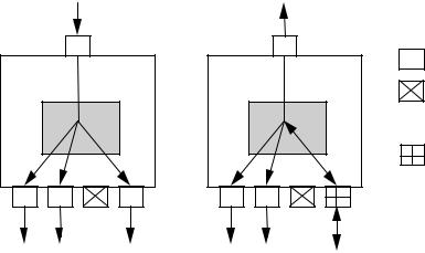
11.1.2.2 Resume Connectivity
Hubs exhibit different connectivity behaviors for upstreamand downstream-directed resume signaling. A hub that is suspended reflects resume signaling from its upstream port to all of its enabled downstream ports. Figure 11-3 illustrates hub upstream and downstream resume connectivity.
Upstream |
Port |
Downstream
Ports
Upstream
Port
Enabled Port
Disabled or
Suspended
Port
Enabled or
Suspended
Port
Downstream Connectivity
Source of resume signaling
Upstream Connectivity
Figure 11-3. Resume Connectivity
If a hub is suspended and detects resume signaling from a selectively suspended or an enabled downstream port, the hub reflects that signaling upstream and to all of its enabled downstream ports, including the port that initiated the resume sequence. Resume signaling is not reflected to disabled or suspended ports. A detailed discussion of resume connectivity appears in Section 11.9.
11.1.2.3 Hub Fault Recovery Mechanisms
Hubs are the essential USB component for establishing connectivity between the host and other devices. It is vital that any connectivity faults, especially those that might result in a deadlock, be detected and prevented from occurring. Hubs need to handle connectivity faults only when they are in the repeater mode.
Hubs must also be able to detect and recover from lost or corrupted packets that are addressed to the Hub Controller. Because the Hub Controller is, in fact, another USB device, it must adhere to the same timeout rules as other USB devices, as described in Chapter 8.
11.2 Hub Frame Timer
Each hub has a frame timer whose timing is derived from the hub’s local clock and is synchronized to the host frame period by the host-generated Start-of-Frame (SOF). The frame timer provides timing references that are used to allow the hub to detect a babbling device and prevent the hub from being disabled by the upstream hub. The hub frame timer must track the host frame period and be capable of remaining synchronized with the host even if two consecutive SOF tokens are missed by the hub.
232
Universal Serial Bus Specification Revision 1.1
The frame timer must lock to the host’s frame timing for worst case tolerances and offsets between the host and hub. The offsets have to accommodate the hub oscillator tolerance ( 500ppm) and accuracy
( 2500ppm) as well as the host’s allowed frame tolerance of 500ppm. The range of the hub frame timer is:
12,000 * 1 (hub accuracy + hub tolerance + host tolerance)
The host tolerance is allowed to be 500ppm, meaning that a frame time is between 0.9995ms and 1.0005ms, absolute. If the hub’s oscillator is at the limits of its accuracy and tolerance, it can be running at between 11,964,000Hz and 12,036,000Hz. If the host is generating an SOF every 1.0005ms and the hub is running at 12,036,000Hz, then the hub’s frame timer will count 12,042 times between each SOF. If the host is generating an SOF every 0.9995ms and the hub is running at 11,964,000Hz, then the hub’s frame timer will count 11,958 times between each SOF. If the hub accuracy and tolerance are both zero, the hub frame timer range is 6 bit times.
11.2.1 Frame Timer Synchronization
A hub’s frame timer is clocked by the hub’s clock source and is synchronized to SOF packets that are derived from the host’s frame timer. After a reset or resume, the hub’s frame timer is not synchronized. Whenever the hub receives two consecutive SOF packets, its frame timer should be synchronized. Synchronized is synonymous with lock(ed). A example for a method of constructing a timer that properly synchronizes is as follows.
The hub maintains three timer values: frame timer (down counter), current frame (up counter), and next frame (register). After a reset or resume, a flag is set to indicate that the frame timer is not synchronized.
When the first SOF token is detected, the current frame timer resets and starts counting once per hub bit time. On the next SOF, if the timer has not rolled over, the value in the current frame timer is loaded into the next frame register and into the frame timer. The current frame timer is reset to zero and continues to count and the flag is set to indicate that the frame timer is locked. If the current frame timer has rolled over (exceeded 12,043 – a test at 16,383 is adequate), then an SOF was missed and the frame timer and next frame values are not loaded and the flag indicating that the timer is not synchronized remains set.
Whenever the frame timer counts down to zero, the current value of the next frame register is loaded into the frame timer. When an SOF is detected, and the current frame timer has not rolled over, the value of the current frame timer is loaded into the frame timer and the next frame registers. The current frame timer is then reset to zero and continues to count. If the current frame timer has rolled over, then the value in the next frame register is loaded into the frame timer. This process can cause the frame timer to be updated twice in a single frame: once when the frame timer reaches zero and once when the SOF is detected.
The synchronization circuit described above depends on successfully decoding an SOF packet identifier (PID). This means that the frame timer will be synchronized to a time that is at least 16 bit times into the frame. Each implementation will take some time to react to the SOF decode and set the appropriate timer/counter values. (This reaction time is implementation-dependent but is assumed to be less than four full-speed bit times.) Subsequent sections describe the actions that are controlled by the frame timer. These actions are defined at the EOF1, EOF2, and EOF points, which should nominally be the same points in time throughout the bus. EOF1 and EOF2 are defined in later sections. These sections assume that the hub’s frame timer will count to zero at the end of the frame (EOF). The circuitry described above will have the frame timer counting to zero 16-20 bit times after the start of a frame (or end of previous frame). The timings and bit offsets in the later sections should be advanced to account for this offset (add 16-20 bit times to the EOF1 and EOF2 points.)
The frame timer provides a indication to the hub Repeater state machine to indicate that the frame timer has synchronized to SOF and that the frame timer is capable of generating the EOF1 and EOF2 timing points. This signal is important after a global resume because of the possibility that a device may have been detached and a different speed device attached while the host was generating a long resume (several seconds) and the disconnect cannot be detected. A different speed device will bias D+ and D- to appear
233
Universal Serial Bus Specification Revision 1.1
like a K on the hub which would then be treated as an SOP and, unless inhibited, this SOP would propagate though the resumed hubs. Since the hubs would not have seen any SOF’s at this point, the hubs would not be synchronized and, thus, unable to generate the EOF1 and EOF2 timing points. The only recovery from this would be for the host to reset and re-enumerate the section of the bus containing the changed device. This scenario is prevented by inhibiting any downstream port from establishing connectivity until the hub is locked after a resume.
11.2.2 EOF1 and EOF2 Timing Points
The EOF1 and EOF2 are timing points that are derived from the hub’s frame timer. These timing points are used to ensure that devices and hubs do not interfere with the proper transmission of the SOF packet from the host. These timing points have meaning only when the frame timer has been synchronized to the SOF.
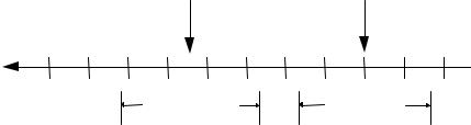
The host and hub frame markers, while all synchronized to the host’s SOF, are subject to certain skews that dictate the placement of the EOF points. Figure 11-4 illustrates critical End-of-Frame (EOF) timing points. Table 11-1 summarizes the host and hub EOF timing points.
|
|
EOF1 |
|
EOF2 |
|
Bit times |
|
|
|
|
SOF |
|
|
|
|
|
|
50 |
40 |
30 |
20 |
10 |
0 |
|
|
EOF1 range |
|
EOF2 range |
|
Figure 11-4. EOF Timing Points
At the EOF2 point, any port that has upstream connectivity will be disabled as a babbler. Hubs prevent becoming disabled by sending an End-of-Packet (EOP) to the upstream hub before that hub reaches its EOF2 point (i.e., at EOF1).
Note: a hub is permitted to send the EOP if upstream connectivity is not established at EOF1 time. A hub must send the EOP if connectivity is established from any downstream port at the EOF1 point.
The EOF2 point is defined to occur at least one bit time before the first bit of the SYNC for an SOP. The period allowed for an EOP is four full-speed bit times (the upstream port on a hub is always full-speed.)
Although the hub is synchronized to the SOF, timing skew can accumulate between the host and a hub or between hubs. This timing skew represents the difference between different frame timers on different hubs and the host. The total accumulated skew can be as large as 9 bit times. This is composed of 1 bit times per frame of quantization error and 1 bit per frame of wander. The quantization error occurs when the hub times the interval between SOFs and arrives at a value that is off by a fraction of a bit time but, due to quantization, is rounded to a full bit. Frame wander occurs when the host's frame timer is adjusted by the USB System Software so that the value sampled by the hub in a previous frame differs from the frame interval being used by the host. These values accumulate over multiple frames because SOF packets can be lost and the hub cannot resynchronize its frame timer. This specification allows for the loss of two consecutive SOFs. During this interval the quantization error accumulates to 3 bit times and the wander accumulates to 1 2 3 = 6 for a total of 9 bit times of accumulated skew in three frames. This skew timing affects the placement of the EOF1 and EOF2 points as follows.
Note: although the USB System Software is not allowed to cause the frame interval to change more than one bit time every six frames, the hub skew timing assumes that the frame interval can change one bit time per frame. This cannot be reduced because it would create interoperability problems with hubs designed to previous versions of this specification.
234