

- •Chapter 1
- •1.1 Motivation
- •1.2 Objective of the Specification
- •1.3 Scope of the Document
- •1.4 Document Organization
- •Chapter 2
- •Chapter 3
- •3.1 Goals for the Universal Serial Bus
- •3.2 Taxonomy of Application Space
- •3.3 Feature List
- •Chapter 4
- •4.1 USB System Description
- •4.1.1 Bus Topology
- •4.2 Physical Interface
- •4.2.1 Electrical
- •4.2.2 Mechanical
- •4.3 Power
- •4.3.1 Power Distribution
- •4.3.2 Power Management
- •4.4 Bus Protocol
- •4.5 Robustness
- •4.5.1 Error Detection
- •4.5.2 Error Handling
- •4.6 System Configuration
- •4.6.1 Attachment of USB Devices
- •4.6.2 Removal of USB Devices
- •4.6.3 Bus Enumeration
- •4.7 Data Flow Types
- •4.7.1 Control Transfers
- •4.7.2 Bulk Transfers
- •4.7.3 Interrupt Transfers
- •4.7.4 Isochronous Transfers
- •4.7.5 Allocating USB Bandwidth
- •4.8 USB Devices
- •4.8.1 Device Characterizations
- •4.8.2 Device Descriptions
- •4.9 USB Host: Hardware and Software
- •4.10 Architectural Extensions
- •Chapter 5
- •5.1 Implementer Viewpoints
- •5.2 Bus Topology
- •5.2.1 USB Host
- •5.2.2 USB Devices
- •5.2.3 Physical Bus Topology
- •5.2.4 Logical Bus Topology
- •5.2.5 Client Software-to-function Relationship
- •5.3 USB Communication Flow
- •5.3.1 Device Endpoints
- •5.3.2 Pipes
- •5.4 Transfer Types
- •5.5 Control Transfers
- •5.5.1 Control Transfer Data Format
- •5.5.2 Control Transfer Direction
- •5.5.3 Control Transfer Packet Size Constraints
- •5.5.4 Control Transfer Bus Access Constraints
- •5.5.5 Control Transfer Data Sequences
- •5.6 Isochronous Transfers
- •5.6.1 Isochronous Transfer Data Format
- •5.6.2 Isochronous Transfer Direction
- •5.6.3 Isochronous Transfer Packet Size Constraints
- •5.6.4 Isochronous Transfer Bus Access Constraints
- •5.6.5 Isochronous Transfer Data Sequences
- •5.7 Interrupt Transfers
- •5.7.1 Interrupt Transfer Data Format
- •5.7.2 Interrupt Transfer Direction
- •5.7.3 Interrupt Transfer Packet Size Constraints
- •5.7.4 Interrupt Transfer Bus Access Constraints
- •5.7.5 Interrupt Transfer Data Sequences
- •5.8 Bulk Transfers
- •5.8.1 Bulk Transfer Data Format
- •5.8.2 Bulk Transfer Direction
- •5.8.3 Bulk Transfer Packet Size Constraints
- •5.8.4 Bulk Transfer Bus Access Constraints
- •5.8.5 Bulk Transfer Data Sequences
- •5.9 Bus Access for Transfers
- •5.9.1 Transfer Management
- •5.9.2 Transaction Tracking
- •5.9.3 Calculating Bus Transaction Times
- •5.9.4 Calculating Buffer Sizes in Functions and Software
- •5.9.5 Bus Bandwidth Reclamation
- •5.10 Special Considerations for Isochronous Transfers
- •5.10.1 Example Non-USB Isochronous Application
- •5.10.2 USB Clock Model
- •5.10.3 Clock Synchronization
- •5.10.4 Isochronous Devices
- •5.10.5 Data Prebuffering
- •5.10.6 SOF Tracking
- •5.10.7 Error Handling
- •5.10.8 Buffering for Rate Matching
- •Chapter 6
- •6.1 Architectural Overview
- •6.3 Cable
- •6.4 Cable Assembly
- •6.4.1 Detachable Cable Assemblies
- •6.4.3 Low-speed Captive Cable Assemblies
- •6.4.4 Prohibited Cable Assemblies
- •6.5.1 USB Icon Location
- •6.5.2 USB Connector Termination Data
- •6.5.3 Series “A” and Series “B” Receptacles
- •6.5.4 Series “A” and Series “B” Plugs
- •6.6.1 Description
- •6.6.2 Construction
- •6.6.3 Electrical Characteristics
- •6.6.4 Cable Environmental Characteristics
- •6.6.5 Listing
- •6.7 Electrical, Mechanical and Environmental Compliance Standards
- •6.7.1 Applicable Documents
- •6.8 USB Grounding
- •Chapter 7
- •7.1 Signaling
- •7.1.1 USB Driver Characteristics
- •7.1.2 Data Signal Rise and Fall
- •7.1.3 Cable Skew
- •7.1.4 Receiver Characteristics
- •7.1.5 Device Speed Identification
- •7.1.6 Input Characteristics
- •7.1.7 Signaling Levels
- •7.1.8 Data Encoding/Decoding
- •7.1.9 Bit Stuffing
- •7.1.10 Sync Pattern
- •7.1.11 Data Signaling Rate
- •7.1.12 Frame Interval and Frame Interval Adjustment
- •7.1.13 Data Source Signaling
- •7.1.14 Hub Signaling Timings
- •7.1.15 Receiver Data Jitter
- •7.1.16 Cable Delay
- •7.1.17 Cable Attenuation
- •7.1.18 Bus Turn-around Time and Inter-packet Delay
- •7.1.19 Maximum End-to-end Signal Delay
- •7.2 Power Distribution
- •7.2.1 Classes of Devices
- •7.2.2 Voltage Drop Budget
- •7.2.3 Power Control During Suspend/Resume
- •7.2.4 Dynamic Attach and Detach
- •7.3 Physical Layer
- •7.3.1 Regulatory Requirements
- •7.3.2 Bus Timing/Electrical Characteristics
- •7.3.3 Timing Waveforms
- •Chapter 8
- •8.1 Bit Ordering
- •8.2 SYNC Field
- •8.3 Packet Field Formats
- •8.3.1 Packet Identifier Field
- •8.3.2 Address Fields
- •8.3.3 Frame Number Field
- •8.3.4 Data Field
- •8.3.5 Cyclic Redundancy Checks
- •8.4 Packet Formats
- •8.4.1 Token Packets
- •8.4.2 Start-of-Frame Packets
- •8.4.3 Data Packets
- •8.4.4 Handshake Packets
- •8.4.5 Handshake Responses
- •8.5 Transaction Formats
- •8.5.1 Bulk Transactions
- •8.5.2 Control Transfers
- •8.5.3 Interrupt Transactions
- •8.5.4 Isochronous Transactions
- •8.6 Data Toggle Synchronization and Retry
- •8.6.1 Initialization via SETUP Token
- •8.6.2 Successful Data Transactions
- •8.6.3 Data Corrupted or Not Accepted
- •8.6.4 Corrupted ACK Handshake
- •8.6.5 Low-speed Transactions
- •8.7 Error Detection and Recovery
- •8.7.1 Packet Error Categories
- •8.7.2 Bus Turn-around Timing
- •8.7.3 False EOPs
- •8.7.4 Babble and Loss of Activity Recovery
- •Chapter 9
- •9.1 USB Device States
- •9.1.1 Visible Device States
- •9.1.2 Bus Enumeration
- •9.2 Generic USB Device Operations
- •9.2.1 Dynamic Attachment and Removal
- •9.2.2 Address Assignment
- •9.2.3 Configuration
- •9.2.4 Data Transfer
- •9.2.5 Power Management
- •9.2.6 Request Processing
- •9.2.7 Request Error
- •9.3 USB Device Requests
- •9.3.1 bmRequestType
- •9.3.2 bRequest
- •9.3.3 wValue
- •9.3.4 wIndex
- •9.3.5 wLength
- •9.4 Standard Device Requests
- •9.4.1 Clear Feature
- •9.4.2 Get Configuration
- •9.4.3 Get Descriptor
- •9.4.4 Get Interface
- •9.4.5 Get Status
- •9.4.6 Set Address
- •9.4.7 Set Configuration
- •9.4.8 Set Descriptor
- •9.4.9 Set Feature
- •9.4.10 Set Interface
- •9.4.11 Synch Frame
- •9.5 Descriptors
- •9.6 Standard USB Descriptor Definitions
- •9.6.1 Device
- •9.6.2 Configuration
- •9.6.3 Interface
- •9.6.4 Endpoint
- •9.6.5 String
- •9.7 Device Class Definitions
- •9.7.1 Descriptors
- •9.7.2 Interface(s) and Endpoint Usage
- •9.7.3 Requests
- •Chapter 10
- •10.1 Overview of the USB Host
- •10.1.1 Overview
- •10.1.2 Control Mechanisms
- •10.1.3 Data Flow
- •10.1.4 Collecting Status and Activity Statistics
- •10.1.5 Electrical Interface Considerations
- •10.2 Host Controller Requirements
- •10.2.1 State Handling
- •10.2.2 Serializer/Deserializer
- •10.2.3 Frame Generation
- •10.2.4 Data Processing
- •10.2.5 Protocol Engine
- •10.2.6 Transmission Error Handling
- •10.2.7 Remote Wakeup
- •10.2.8 Root Hub
- •10.2.9 Host System Interface
- •10.3 Overview of Software Mechanisms
- •10.3.1 Device Configuration
- •10.3.2 Resource Management
- •10.3.3 Data Transfers
- •10.3.4 Common Data Definitions
- •10.4 Host Controller Driver
- •10.5 Universal Serial Bus Driver
- •10.5.1 USBD Overview
- •10.5.2 USBD Command Mechanism Requirements
- •10.5.3 USBD Pipe Mechanisms
- •10.5.4 Managing the USB via the USBD Mechanisms
- •10.5.5 Passing USB Preboot Control to the Operating System
- •10.6 Operating System Environment Guides
- •Chapter 11
- •11.1 Overview
- •11.1.1 Hub Architecture
- •11.1.2 Hub Connectivity
- •11.2 Hub Frame Timer
- •11.2.1 Frame Timer Synchronization
- •11.2.2 EOF1 and EOF2 Timing Points
- •11.3 Host Behavior at End-of-Frame
- •11.3.1 Latest Host Packet
- •11.3.2 Packet Nullification
- •11.3.3 Transaction Completion Prediction
- •11.4 Internal Port
- •11.4.1 Inactive
- •11.4.2 Suspend Delay
- •11.4.3 Full Suspend (Fsus)
- •11.4.4 Generate Resume (GResume)
- •11.5 Downstream Ports
- •11.5.1 Downstream Port State Descriptions
- •11.6 Upstream Port
- •11.6.1 Receiver
- •11.6.2 Transmitter
- •11.7 Hub Repeater
- •11.7.1 Wait for Start of Packet from Upstream Port (WFSOPFU)
- •11.7.2 Wait for End of Packet from Upstream Port (WFEOPFU)
- •11.7.3 Wait for Start of Packet (WFSOP)
- •11.7.4 Wait for End of Packet (WFEOP)
- •11.8 Bus State Evaluation
- •11.8.1 Port Error
- •11.8.2 Speed Detection
- •11.8.3 Collision
- •11.9 Suspend and Resume
- •11.10 Hub Reset Behavior
- •11.10.1 Hub Receiving Reset on Upstream Port
- •11.11 Hub Port Power Control
- •11.11.1 Multiple Gangs
- •11.12 Hub I/O Buffer Requirements
- •11.12.1 Pull-up and Pull-down Resistors
- •11.12.2 Edge Rate Control
- •11.13 Hub Controller
- •11.13.1 Endpoint Organization
- •11.13.2 Hub Information Architecture and Operation
- •11.13.3 Port Change Information Processing
- •11.13.4 Hub and Port Status Change Bitmap
- •11.13.5 Over-current Reporting and Recovery
- •11.14 Hub Configuration
- •11.15 Descriptors
- •11.15.1 Standard Descriptors
- •11.15.2 Class-specific Descriptors
- •11.16 Requests
- •11.16.1 Standard Requests
- •11.16.2 Class-specific Requests
- •Index
Universal Serial Bus Specification Revision 1.1
11.6 Upstream Port
The upstream port has four components: transmitter, transmitter state machine, receiver and receiver state machine. The transmitter and its state machine are the Transmitter, while the receiver and its state machine are the Receiver. Both the transmitter and receiver have differential and single-ended components. The differential transmitter and receiver can send/receive 'J' or 'K' to/from the bus while the single-ended components are used to send/receive SE0, suspend, and resume signaling. In this section, when it is necessary to differentiate the signals sent/received by the differential component of the transmitter/receiver from those of the single-ended components, DJ and DK will be used to denote the differential signal and SJ, SK and SE0 will be used for the single-ended signals.
It is assumed that the differential transmitter and receiver are turned off during suspend to minimize power consumption. The single-ended components are left on at all times, as they will take minimal power.
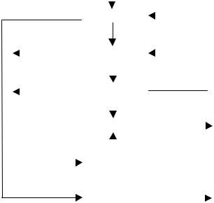
11.6.1 Receiver
The receiver state machine is responsible for monitoring the signaling state of the upstream connection to detect long-term signaling events such as bus reset, resume, and suspend. Figure 11-7 illustrates the state transition diagram. Table 11-4 defines the signals and events referenced in Figure 11-7.
Tx_active
J |
State Machine Exports: |
Rx_Bus_Reset(Bus_Reset)
ReceivingJ
Rx_Suspend(Suspend)
Rx_Resume(Resume)
 EOI
EOI
Suspend
K
ReceivingK
# = Logical OR
Tx_resume # K
EOI
Resume
SE0
ReceivingSE0
EOI
POR
Bus_Reset
Figure 11-7. Upstream Port Receiver State Machine
244
Universal Serial Bus Specification Revision 1.1
Table 11-4. Upstream Hub Port Receiver Signal/Event Definitions
Signal/Event |
Event/Signal |
Description |
Name |
Source |
|
|
|
|
Tx_active |
Transmitter |
Transmitter in the Active state |
|
|
|
J |
Internal |
Receiving a 'J' (IDLE) on the upstream port |
|
|
|
EOI |
Internal |
End of timed interval |
|
|
|
K |
Internal |
Receiving a 'K' on the upstream port |
|
|
|
Tx_resume |
Transmitter |
Transmitter is in the Sresume state |
|
|
|
SE0 |
Internal |
Receiving an SE0 on the upstream port |
|
|
|
POR |
Implementation- |
Power_On_Reset |
|
dependent |
|
|
|
|
11.6.1.1 ReceivingJ
This state is entered from any state except the Suspend state if the receiver detects an SJ (or Idle) condition on the bus or while the Transmitter is in the Active state.
This is a timed state with an interval of 3ms. The timer is reset each time this state is entered.
The timer only advances if the Transmitter is in the Inactive state.
11.6.1.2 Suspend
This state is entered if the 3ms timer expires in the ReceivingJ state. When the Receiver enters this state, the Hub Controller starts a 2ms timer. If that timer expires while the Receiver is still in this state, then the Hub Controller is suspended. When the Hub Controller is suspended, it may generate resume signaling.
11.6.1.3 ReceivingK
This state is entered from any state except the Resume state when the receiver detects an SK condition on the bus and the Hub Repeater is in the WFSOP or WFSOPFU state. This is a timed state with a duration of 2.5 s to 100 s. The timer is reset each time this state starts.
11.6.1.4 Resume
This state is entered from the ReceivingK state when the timer expires.
This state is also entered from the Suspend state while the Transmitter is in the Sresume state or if there is a transition to the K state on the upstream port.
If the hub enters this state when its timing reference is not available, the hub may remain in this state until the hub’s timing reference becomes stable. If this state is being held pending stabilization of the hub’s clock, the Receiver should provide a K to the repeater for propagation to the downstream ports. When clocks are stable, the Receiver should repeat the incoming signals.
Note: constraints on hub behavior after reset require that the hub be able to start clocks and get them stable in less than 10ms.
245
Universal Serial Bus Specification Revision 1.1
11.6.1.5 ReceivingSE0
This state is entered from any state except Bus_Reset when the receiver detects an SE0 condition and the Hub Repeater is in the WFSOP or WFSOPFU state. This is a timed state. The minimum interval for this state is 2.5 s. The maximum depends on the hub but this interval must timeout early enough such that if the width of the SE0 on the upstream port is only 10ms, the Receiver will enter the Bus_Reset state with sufficient time remaining in the 10ms interval for the hub to complete its reset processing. Furthermore, if the hub is suspended when the Receiver enters this state, the hub must be able to start its clocks, time this interval, and complete its reset processing within 10ms. It is preferred that this interval be as long as possible given the constraints listed here. This will provide for the maximum immunity to noise on the upstream port and reduce the probability that the device will reset in the presence of noise before the upstream hub disables the port.
The timer is reset each time this state starts.
11.6.1.6 Bus_Reset
This state is entered from the ReceivingSE0 state when the timer expires. As long as the port continues to receive SE0, the Receiver will remain in this state.
This state is also entered while power-on-reset (POR) is being generated by the hub’s local circuitry. The state machine cannot exit this state while POR is active.
11.6.2 Transmitter
This state machine is used to monitor the upstream port while the Hub Repeater has connectivity in the upstream direction. The purpose of this monitoring activity is to prevent propagation of erroneous indications in the upstream direction. In particular, this machine prevents babble and disconnect events on the downstream ports of this hub from propagating and causing this hub to be disabled or disconnected by the hub to which it is attached. Figure 11-8 is the transmitter state transition diagram. Table 11-5 defines the signals and events referenced in Figure 11-8.
|
|
|
|
Rx_Bus_Reset |
|
|
|
|
|
||
|
|
|
|
|
|
|
|
|
|
|
State Machine Exports: |
|
|
|
|
|
|
|
|
|
|
|
|
|
|
|
|
Inactive |
|
|
|
|
|||
|
|
|
|
|
|
|
|
||||
|
|
|
|
|
|
|
|
|
|
|
|
|
|
|
|
|
|
Rptr_WFEOP & |
|
|
Tx_Active(Active) |
||
|
EOF1 |
|
|
|
!Rx_Suspend |
|
|
Tx_Resume(Sresume) |
|||
|
|
Active |
|
|
|
|
|
||||
|
|
|
|
|
|
|
|
|
|||
|
|
|
|
|
|
|
|
|
|
|
|
|
SE0sent |
|
|
|
|
|
|
|
|||
|
EOF1 |
|
|
|
|
|
K |
|
|
|
|
|
RepeatingSE0 |
|
|
# = Logical OR |
|||||||
|
|
|
|
|
|
|
|
||||
|
|
|
|
|
|
|
|
|
|
|
|
|
EOI # J |
|
|
|
|
||||||
|
|
|
|
EOI |
|
|
& = Logical AND |
||||
|
|
|
|
||||||||
|
|
|
|
|
|
|
|
|
|
||
|
|
|
|
SendJ |
|
||||||
|
|
|
|
|
|
|
|
||||
|
|
|
|
|
|
|
|
! = Logical NOT |
|||
|
|
|
|
|
|
|
|
|
|
|
|
|
|
|
|
|
|
EOI |
|
|
|||
|
|
|
|
|
|
|
|
|
|
|
|
|
|
|
|
|
|
|
|
|
|
|
|
|
|
|
|
GEOPTU |
|
|
|
|
|
||
Rx_Suspend & |
|
|
|
|
|
|
|||||
|
|
|
|
|
|
|
|
|
|||
|
|
|
|
|
|
|
|
|
|||
Rptr_WFEOP |
|
|
|
|
|
EOI |
|
|
|
||
|
Sresume |
|
|
|
|||||||
|
|
|
|
|
|
|
|
|
|||
|
|
|
|
|
|
|
|
|
|
|
|
Figure 11-8. Upstream Hub Port Transmitter State Machine
246
Universal Serial Bus Specification Revision 1.1
Table 11-5. Upstream Hub Port Transmit Signal/Event Definitions
Signal/Event |
Event/Signal |
Description |
Name |
Source |
|
|
|
|
Rx_Bus_Reset |
Receiver |
Receiver is in the Bus_Reset state |
|
|
|
EOF1 |
Frame Timer |
Hub frame time has reached the EOF1 point or is between |
|
|
EOF1 and the end of the frame |
|
|
|
J |
Internal |
Transmitter transitions to sending a 'J' and transmits a 'J' |
|
|
|
Rptr_WFEOP |
Hub Repeater |
Hub Repeater is in the WFOEP state |
|
|
|
K |
Internal |
Transmitter transmits a 'K' |
|
|
|
SE0sent |
Internal |
At least one bit time of SE0 has been sent through the |
|
|
transmitter |
|
|
|
Rx_Suspend |
Receiver |
Receiver is in Suspend state |
|
|
|
EOI |
Internal |
End of timed interval |
|
|
|
11.6.2.1 Inactive
This state is entered at the end of the SendJ state or while the Receiver is in the Bus_Reset state. This state is also entered at the end of the Sresume state. While the transmitter is in this state, both the differential and single-ended transmit circuits are disabled and placed in their high-impedance state.
11.6.2.2 Active
This state is entered from the Inactive state when the Hub Repeater transitions to the WFEOP state. This state is entered from the RepeatingSE0 state if the first transition after the SE0 is not to the J state. In this state, the data from a downstream port is repeated and transmitted on the upstream port.
11.6.2.3 RepeatingSE0
The port enters this state from the Active state when one bit time of SE0 has been sent on the upstream port. While in this state, the transmitter is still active and downstream signaling is repeated on the port. This is a timed state with a duration of 23 full-speed bit times.
11.6.2.4 SendJ
The port enters this state from the RepeatingSE0 state if either the bit timer reaches 23 or the repeated signaling changes from SE0 to 'J'. This state is also entered at the end of the GEOPTU state. This state lasts for one full-speed bit time. During this state, the hub drives an SJ on the port.
247
Universal Serial Bus Specification Revision 1.1
11.6.2.5 Generate End of Packet Towards Upstream Port (GEOPTU)
The port enters this state from the Active or RepeatingSEO state if the frame timer reaches the EOF1 point.
In this state, the port transmits SE0 for two full-speed bit times.
11.6.2.6 Send Resume (Sresume)
The port enters this state from the Inactive state if the Receiver is in the Suspend state and the Hub Repeater transitions to the WFEOP state. This indicates that a downstream device (or the port to the Hub Controller) has generated resume signaling, causing upstream connectivity to be established.
On entering this state, the hub will restart clocks if they had been turned off during the Suspend state. While in this state, the Transmitter will drive a 'K' on the upstream port. While the Transmitter is in this state, the Receiver is held in the Resume state. While in the Resume state, all downstream ports that are in the Enable state are placed in the Transmit state and the resume on this port is transmitted to those downstream ports.
The port stays in this state for at least 1ms but for no more than 15ms.
248