

Universal Serial Bus Specification Revision 1.1
scheduled transactions have completed. The bus time made available due to less bit stuffing can be reused as discussed in Section 5.9.5.
The Host_Delay term in the equations is Host Controllerand system-dependent and allows for additional time a Host Controller may require due to delays in gaining access to memory or other implementation dependencies. This term is incorporated into an implementation of these equations by using the transfer management functions provided by the HCD interface. These equations are typically implemented by a combination of USBD and HCD software working in cooperation. The results of these calculations are used to determine whether a transfer or pipe creation can be supported in a given USB configuration.
5.9.4 Calculating Buffer Sizes in Functions and Software
Client software and functions both need to provide buffer space for pending data transactions awaiting their turn on the bus. For non-isochronous pipes, this buffer space needs to be just large enough to hold the next data packet. If more than one transaction request is pending for a given endpoint, the buffering for each transaction must be supplied. Methods to calculate the precise absolute minimum buffering a function may require because of specific interactions defined between its client software and the function are outside the scope of the USB Specification.
The Host Controller is expected to be able to support an unlimited number of transactions pending for the bus subject to available system memory for buffer and descriptor space, etc. Host Controllers are allowed to limit how many frames into the future they allow a transaction to be requested.
For isochronous pipes, Section 5.10.4 describes details affecting host side and device side buffering requirements. In general, buffers need to be provided to hold approximately twice the amount of data that can be transferred in 1ms.
5.9.5 Bus Bandwidth Reclamation
The USB bandwidth and bus access are granted based on a calculation of worst case bus transmission time and required latencies. However, due to the constraints placed on different transfer types and the fact that the bit stuffing bus time contribution is calculated as a constant but is data-dependent, there will frequently be bus time remaining in each frame time versus what the frame transmission time was calculated to be. In order to support the most efficient use of the bus bandwidth, control and bulk transfers are candidates to be moved over the bus as bus time becomes available. Exactly how a Host Controller supports this is implementation-dependent. A Host Controller can take into account the transfer types of pending IRPs and implementation-specific knowledge of remaining frame time to reuse reclaimed bandwidth.
5.10 Special Considerations for Isochronous Transfers
Support for isochronous data movement between the host and a device is one of the system capabilities supported by the USB. Delivering isochronous data reliably over the USB requires careful attention to detail. The responsibility for reliable delivery is shared by several USB entities:
The device/function
The bus
The Host Controller
One or more software agents.
Because time is a key part of an isochronous transfer, it is important for USB designers to understand how time is dealt with within the USB by these different entities.
All isochronous devices must report their capabilities in the form of device-specific descriptors. The capabilities should also be provided in a form that the potential customer can use to decide whether the
55
Universal Serial Bus Specification Revision 1.1
device offers a solution to his problem(s). The specific capabilities of a device can justify price differences.
In any communication system, the transmitter and receiver must be synchronized enough to deliver data robustly. In an asynchronous communication system, data can be delivered robustly by allowing the transmitter to detect that the receiver has not received a data item correctly and simply retrying transmission of the data.
In an isochronous communication system, the transmitter and receiver must remain timeand datasynchronized to deliver data robustly. The USB does not support transmission retry of isochronous data so that minimal bandwidth can be allocated to isochronous transfers and time synchronization is not lost due to a retry delay. However, it is critical that a USB isochronous transmitter/receiver pair still remain synchronized both in normal data transmission cases and in cases where errors occur on the bus.
In many systems that deal with isochronous data, a single global clock is used to which all entities in the system synchronize. An example of such a system is the PSTN (Public Switched Telephone Network). Given that a broad variety of devices with different natural frequencies may be attached to the USB, no single clock can provide all the features required to satisfy the synchronization requirements of all devices and software while still supporting the cost targets of mass-market PC products. The USB defines a clock model that allows a broad range of devices to coexist on the bus and have reasonable cost implementations.
This section presents options or features that can be used by isochronous endpoints to minimize behavior differences between a non-USB implemented function and a USB version of the function. An example is included to illustrate the similarities and differences between the non-USB and USB versions of a function.
The remainder of the section presents the following key concepts:
USB Clock Model: What clocks are present in a USB system that have impact on isochronous data transfers
USB Frame Clock-to-function Clock Synchronization Options: How the USB frame clock can relate to a function clock
SOF Tracking: Responsibilities and opportunities of isochronous endpoints with respect to the SOF token and USB frames
Data Prebuffering: Requirements for accumulating data before generation, transmission, and consumption
Error Handling: Isochronous-specific details for error handling
Buffering for Rate Matching: Equations that can be used to calculate buffer space required for isochronous endpoints.
5.10.1 Example Non-USB Isochronous Application
The example used is a reasonably generalized example. Other simpler or more complex cases are possible and the relevant USB features identified can be used or not as appropriate.
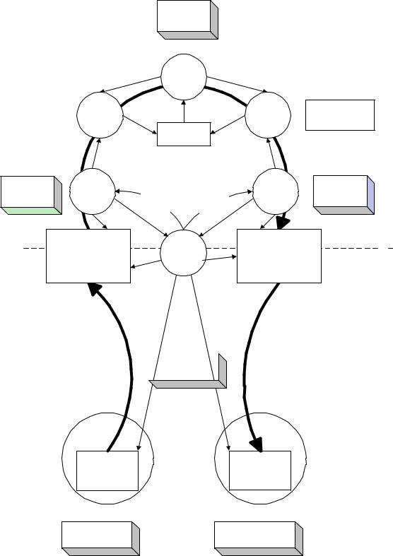
The example consists of an 8kHz mono microphone connected through a mixer driver that sends the input data stream to 44kHz stereo speakers. The mixer expects the data to be received and transmitted at some sample rate and encoding. A rate matcher driver on input and output converts the sample rate and encoding from the natural rate and encoding of the device to the rate and encoding expected by the mixer. Figure 5-13 illustrates this example.
56
Universal Serial Bus Specification Revision 1.1
Each DD has independent service rate
Mixer Device
Driver
|
|
1 speaker DD |
Rate |
Rate |
service period |
Matcher |
Matcher |
(n sample) |
|
Master Clock |
slop buffer |
|
|
20ms service |
Microphone |
Transfer |
Transfer |
Speaker |
20ms service |
|
period |
Device Driver |
Device Driver |
period |
|||
Complete |
||||||
|
|
Complete |
|
|
||
|
|
Interrupt |
|
|
||
|
|
Interrupt |
|
|
||
|
|
|
|
|
||
|
2x160 Byte Buffer |
D M A |
|
2x3528 Byte Buffer |
Software |
|
|
|
Hardware |
||||
|
(2 Services, |
controller |
|
(2 Services, |
||
|
|
|
||||
|
160 samples per service) |
|
|
882 samples per service) |
|
Traditional Bus
(e.g. PCI, ISA, ...)
Single sample
transfers
1 sample at a time |
|
|
|
1 sample at a time |
|
8MHz Bus Clock |
|
||
|
|
|
|
|
|
|
|
|
|
|
|
|
|
|
Mono |
|
CD Stereo |
Microphone |
|
Speakers |
2x1 Byte Buffer |
2x4 |
Byte Buffer |
(2 Samples) |
(2 |
Samples) |
8kHz Sample Clock (1 byte/sample)
44.1KHz Sample Clock
(4 bytes/sample)
Figure 5-13. Non-USB Isochronous Example
57
Universal Serial Bus Specification Revision 1.1
A master clock (which can be provided by software driven from the real time clock) in the PC is used to awaken the mixer to ask the input source for input data and to provide output data to the output sink. In this example, assume it awakens every 20ms. The microphone and speakers each have their own sample clocks that are unsynchronized with respect to each other or the master mixer clock. The microphone produces data at its natural rate (one-byte samples, 8,000 times a second) and the speakers consume data at their natural rate (four-byte samples, 44,100 times a second). The three clocks in the system can drift and jitter with respect to each other. Each rate matcher may also be running at a different natural rate than either the mixer driver, the input source/driver, or output sink/driver.
The rate matchers also monitor the long-term data rate of their device compared to the master mixer clock and interpolate an additional sample or merge two samples to adjust the data rate of their device to the data rate of the mixer. This adjustment may be required every couple of seconds, but typically occurs infrequently. The rate matchers provide some additional buffering to carry through a rate match.
Note: Some other application might not be able to tolerate sample adjustment and would need some other means of accommodating master clock-to-device clock drift or else would require some means of synchronizing the clocks to ensure that no drift could occur.
The mixer always expects to receive exactly a service period of data (20ms service period) from its input device and produce exactly a service period of data for its output device. The mixer can be delayed up to less than a service period if data or space is not available from its input/output device. The mixer assumes that such delays do not accumulate.
The input and output devices and their drivers expect to be able to put/get data in response to a hardware interrupt from the DMA controller when their transducer has processed one service period of data. They expect to get/put exactly one service period of data. The input device produces 160 bytes (ten samples) every service period of 20ms. The output device consumes 3,528 bytes (882 samples) every 20ms service period. The DMA controller can move a single sample between the device and the host buffer at a rate much faster than the sample rate of either device.
The input and output device drivers provide two service periods of system buffering. One buffer is always being processed by the DMA controller. The other buffer is guaranteed to be ready before the current buffer is exhausted. When the current buffer is emptied, the hardware interrupt awakens the device driver and it calls the rate matcher to give it the buffer. The device driver requests a new IRP with the buffer before the current buffer is exhausted.
The devices can provide two samples of data buffering to ensure that they always have a sample to process for the next sample period while the system is reacting to the previous/next sample.
The service periods of the drivers are chosen to survive interrupt latency variabilities that may be present in the operating system environment. Different operating system environments will require different service periods for reliable operation. The service periods are also selected to place a minimum interrupt load on the system, because there may be other software in the system that requires processing time.
58