

Universal Serial Bus Specification Revision 1.1
Chapter 5
USB Data Flow Model
This chapter presents information about how data is moved across the USB. The information in this chapter affects all implementers. The information presented is at a level above the signaling and protocol definitions of the system. Consult Chapter 7 and Chapter 8 for more details about their respective parts of the USB system. This chapter provides framework information that is further expanded in Chapters 9 through 11. All implementers should read this chapter so they understand the key concepts of the USB.
5.1 Implementer Viewpoints
The USB provides communication services between a host and attached USB devices. However, the simple view an end user sees of attaching one or more USB devices to a host, as in Figure 5-1, is in fact a little more complicated to implement than is indicated by the figure. Different views of the system are required to explain specific USB requirements from the perspective of different implementers. Several important concepts and features must be supported to provide the end user with the reliable operation demanded from today’s personal computers. The USB is presented in a layered fashion to ease explanation and allow implementers of particular USB products to focus on the details related to their product.
USB Host |
|
USB Device |
|
||
|
|
|
Figure 5-1. Simple USB Host/Device View
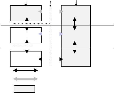
Figure 5-2 shows a deeper overview of the USB, identifying the different layers of the system that will be described in more detail in the remainder of the specification. In particular, there are four focus implementation areas:
USB Physical Device: A piece of hardware on the end of a USB cable that performs some useful end user function.
Client Software: Software that executes on the host, corresponding to a USB device. This client software is typically supplied with the operating system or provided along with the USB device.
USB System Software: Software that supports the USB in a particular operating system. The USB System Software is typically supplied with the operating system, independently of particular USB devices or client software.
USB Host Controller (Host Side Bus Interface): The hardware and software that allows USB devices to be attached to a host.
There are shared rights and responsibilities between the four USB system components. The remainder of this specification describes the details required to support robust, reliable communication flows between a function and its client.
25
Universal Serial Bus Specification Revision 1.1
Host |
Interconnect Physical Device |
|
|||
|
|
|
|
|
|
Client SW |
|
|
|
Function |
Function Layer |
|
|
|
|||
|
|
|
|||
|
|
|
|
|
|
|
|
|
|
|
|
|
|
|
|
|
|
|
|
|
|
|
|
|
|
|
|
|
|
|
USB System |
|
|
|
|
USB Logical |
USB Device |
||||
|
|
|
|
|
|||||||
|
|
|
|
|
|||||||
|
SW |
|
|
|
|
Device |
|||||
|
|
|
|
|
Layer |
||||||
|
|
|
|
|
|
|
|
|
|
|
|
|
|
|
|
|
|
|
|
|
|
|
USB Bus |
|
|
|
|
|
|
|
|
|
|
|
|
|
|
|
|
|
|
|
|
|
|
|
|
|
|
|
|
|
|
|
|
|
|
|
|
|
|
|
|
|
|
|
|
|
|
|
|
|
USB Host |
|
|
|
|
USB Bus |
|||||
|
|
|
|
|
Interface Layer |
||||||
|
Controller |
|
|
|
|
Interface |
|||||
|
|
|
|
|
|
||||||
|
|
|
|
|
|
|
|
|
|
|
|
|
|
|
|
|
|
|
|
|
|
|
|
Actual communications flow
Logical communications flow
Implementation Focus Area
Figure 5-2. USB Implementation Areas
As shown in Figure 5-2, the simple connection of a host to a device requires interaction between a number of layers and entities. The USB Bus Interface layer provides physical/signaling/packet connectivity between the host and a device. The USB Device Layer is the view the USB System Software has for performing generic USB operations with a device. The Function Layer provides additional capabilities to the host via an appropriate matched client software layer. The USB Device and Function layers each have a view of logical communication within their layer that actually uses the USB Bus Interface Layer to accomplish data transfer.
The physical view of USB communication as described in Chapters 6, 7, and 8 is related to the logical communication view presented in Chapters 9 and 10. This chapter describes those key concepts that affect USB implementers and should be read by all before proceeding to the remainder of the specification to find those details most relevant to their product.
To describe and manage USB communication, the following concepts are important:
Bus Topology: Section 5.2 presents the primary physical and logical components of the USB and how they interrelate.
Communication Flow Models: Sections 5.3 through 5.8 describe how communication flows between the host and devices through the USB and defines the four USB transfer types.
Bus Access Management: Section 5.9 describes how bus access is managed within the host to support a broad range of communication flows by USB devices.
Special Consideration for Isochronous Transfers: Section 5.10 presents features of the USB specific to devices requiring isochronous data transfers. Device implementers for non-isochronous devices do not need to read Section 5.10.
26