

s90mec7
.pdfMAN B&W |
5.05 |
|
|
|
Page of 1 |
Engine Outline, Galleries and Pipe Connections
Engine Outline
The total length of the engine at the crankshaft level may vary depending on the equipment to be fitted on the fore end of the engine, such as adjustable counterweights, tuning wheel, moment compensators or PTO, which are shown as alternatives in Section 5.06
Engine Masses and Centre of Gravity
The partial and total engine masses appear from section 19.04, ‘Dispatch Pattern’, to which the masses of water and oil in the engine, Section 5.08, are to be added. The centre of gravity is shown in Section 5.07, in both cases including the water and oil in the engine, but without moment compensators or PTO.
Gallery Outline
Section 5.06 show the gallery outline for engines rated at nominal MCR (L1).
Engine Pipe Connections
The positions of the external pipe connections on the engine are stated in Section 5.09, and the corresponding lists of counterflanges for pipes and turbocharger in Section 5.10.
The flange connection on the turbocharger gas outlet is rectangular, but a transition piece to a circular form can be supplied as an option: 4 60 601.
MAN B&W MC/MC C, ME-B/ME/ME C/ME GI engines
MAN Diesel |
198 47 15 8.3 |
|
MAN B&W Diesel A/S |
5.06 |
|
|
Page 1 of 3
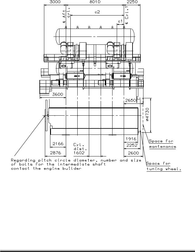
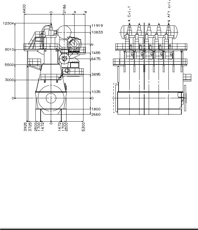
Engine and Gallery Outline
TC type |
a |
b |
c1 |
c2 |
d |
|
|
|
|
|
|
NA70/T09 |
3,830 |
8,870 |
983 |
7,391 |
5,600 |
|
|
|
|
|
|
TPL80 |
3,836 |
8,520 |
922 |
7,330 |
5,410 |
|
|
|
|
|
|
TPL85 |
3,776 |
8,710 |
1,121 |
7,529 |
5,600 |
|
|
|
|
|
|
MET83SD/SE |
3,851 |
8,652 |
1,148 |
7,556 |
5,600 |
|
|
|
|
|
|
178 51 71-5.0
Fig. 5.06.01: Engine outline 6S90ME-C with two turbochargers
S90ME-C |
198 47 22-9.0 |
MAN B&W Diesel A/S |
5.06 |
|
|
Page 2 of 3
178 51 71-5.0
Fig. 5.06.02: Engine outline 6S90ME-C with two turbochargers
S90ME-C |
198 47 22-9.0 |
MAN B&W Diesel A/S |
5.06 |
|
|
Page 3 of 3
178 51 72-7.0
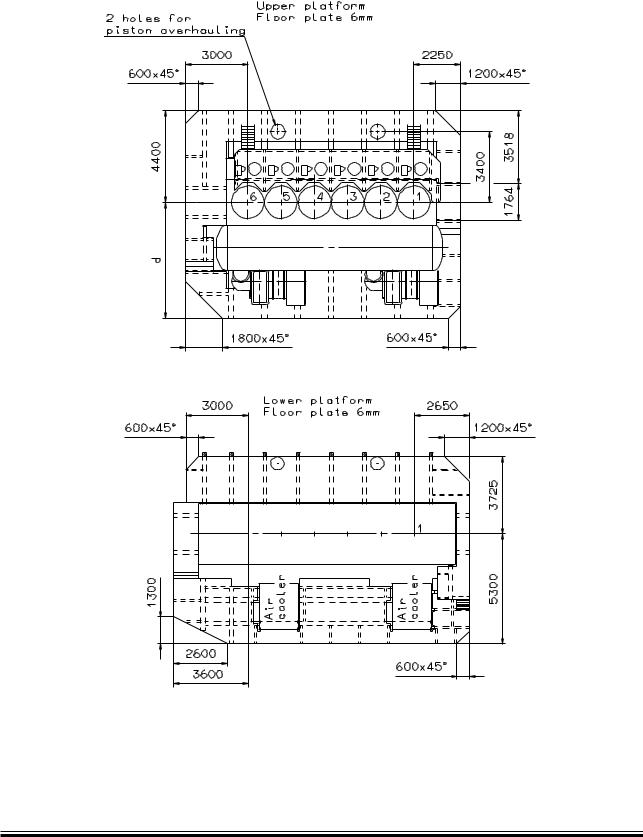
Fig. 5.06.03: Gallery outline 6S90ME-C with two turbochargers
S90ME-C |
198 47 22-9.0 |
MAN B&W Diesel A/S |
5.07 |
|
|
Page 1 of 1
Centre of Gravity
X
Centre of cylinder 1
Y |
Centre of |
|
gravity |
Center of crankshaft
Z
178 32 14-9.0 |
178 27 04-5.0 |
For engines with one turbocharger
No. of cylinders |
6 |
7 |
8 |
9 |
|
|
|
|
|
Distance X mm |
4,770 |
5,590 |
** |
** |
|
|
|
|
|
Distance Y mm |
4,275 |
4,350 |
** |
** |
|
|
|
|
|
Distance Z mm * |
200 |
200 |
** |
** |
|
|
|
|
|
All dimensions are approximate
*) Depends on turbocharger and scavenge air cooler make, type and location.
**) Available on request
Fig. 5.07.01: Data for centre of gravity
S90ME-C |
198 47 02-6.0 |

MAN B&W Diesel A/S |
|
|
|
|
5.08 |
|
|
|
|
|
|
|
|
|
|
|
|
|
|
Page 1 of 1 |
Mass of Water and Oil |
|
|
|
|
|
|
|
|
|
|
|
|
|
|
|
|
Mass of water and oil in engine in service |
|
||
|
|
|
|
|
|
|
|
|
Mass of water |
|
|
Mass of oil |
|
|
|
|
|
|
|
|
No. of |
Jacket cooling |
Scavenge air |
* Total |
Engine |
** Oil pan |
Total |
cylinders |
water |
cooling water |
|
system |
|
|
|
kg |
kg |
kg |
kg |
kg |
kg |
|
|
|
|
|
|
|
6 |
2,300 |
1,500 |
3,800 |
2,300 |
1,850 |
4,150 |
|
|
|
|
|
|
|
7 |
2,700 |
1,850 |
4,550 |
2,700 |
1,700 |
4,400 |
|
|
|
|
|
|
|
8 |
|
|
Data available on request |
|
|
|
|
|
|
|
|
|
|
9 |
|
|
Data available on request |
|
|
|
|
|
|
|
|
|
|
* The stated values are only valid for horizontal mounted engine, without inclination.
** The stated values are only valid for horizontal mounted engine, without inclination, with vertical oil outlets
Fig. 5.08.01: Water and oil in engine
S90MC-C/ME-C |
198 45 69-6.0 |

MAN B&W |
5.09 |
|
|
|
Page of 1 |
Engine Pipe Connections
This section is available on request
MAN Diesel |
198 47 60-0.0 |
|

MAN B&W Diesel A/S |
5.10 |
|
|
Page 1 of 3
Counterflanges
Refe- |
Cyl. |
|
|
|
|
|
|
Flange |
|
Bolts |
|
|
|
|
|
|||
rence |
No. |
|
|
Dia. |
|
PCD |
Thickn. |
Dia. |
|
No. |
Description |
|||||||
A |
6-7 |
325 |
|
275 |
58 |
M24 |
|
12 |
|
|
Starting air inlet |
|||||||
|
|
|
|
|
|
|
|
|
|
|
|
|
|
|
|
|
|
|
B |
6-7 |
|
|
|
Coupling for 20 mm pipe |
|
|
|
|
|
Control air inlet |
|||||||
|
|
|
|
|
|
|
|
|
|
|
|
|
|
|
||||
D |
|
|
|
|
|
|
|
See Figures |
|
|
|
|
|
Exhaust gas outlet |
||||
|
|
|
|
|
|
|
|
|
|
|
|
|
|
|||||
E |
6-7 |
|
|
|
|
|
Nom. diameter 100 mm |
|
|
|
|
|
Venting of lub. oil discharge pipe for turbochargers |
|||||
|
|
|
|
|
|
|
|
|
|
|
|
|
|
|
|
|
|
|
F |
6-7 |
185 |
|
150 |
28 |
M20 |
|
8 |
|
|
Fuel oil outlet |
|||||||
|
|
|
|
|
|
|
|
|
|
|
|
|||||||
K |
6-7 |
320 |
|
280 |
20 |
M20 |
|
8 |
|
|
Fresh cooling water inlet |
|||||||
|
|
|
|
|
|
|
|
|
|
|
|
|||||||
L |
6-7 |
320 |
|
280 |
20 |
M20 |
|
8 |
|
|
Fresh cooling water outlet |
|||||||
|
|
|
|
|
|
|
|
|
|
|
|
|||||||
M |
6-7 |
95 |
|
75 |
10 |
M10 |
|
4 |
|
|
Fresh cooling water deaeration |
|||||||
|
|
|
|
|
|
|
|
|
|
|
|
|||||||
N |
6-7 |
385 |
|
345 |
22 |
M20 |
|
12 |
|
|
Cooling water inlet to air cooler (Central cooling water) |
|||||||
|
|
|
|
|
|
|
|
|
|
|
|
|||||||
P |
6-7 |
385 |
|
345 |
22 |
M20 |
|
12 |
|
|
Cooling water outlet from air cooler (Central cooling water) |
|||||||
|
|
|
|
|
|
|
|
|
|
|
||||||||
N |
6 |
385 |
|
345 |
22 |
M20 |
|
12 |
|
Cooling water inlet to air cooler (Seawater) |
||||||||
|
|
|
|
|
|
|
|
|
|
|
|
|
|
|
|
|
||
7 |
430 |
|
390 |
22 |
M22 |
|
12 |
|
||||||||||
|
|
|
|
|
||||||||||||||
|
|
|
|
|
|
|
|
|
|
|
||||||||
P |
6 |
385 |
|
345 |
22 |
M20 |
|
12 |
|
Cooling water outlet from air cooler (Seawater) |
||||||||
|
|
|
|
|
|
|
|
|
|
|
|
|
|
|
|
|
||
7 |
430 |
|
390 |
22 |
M22 |
|
12 |
|
||||||||||
|
|
|
|
|
||||||||||||||
|
|
|
|
|
|
|
|
|
|
|
|
|
|
|
|
|
||
S |
6-7 |
|
|
|
See special drawing of oil outlet |
|
System oil outlet to bottom tank |
|||||||||||
|
|
|
|
|
|
|
|
|
|
|
|
|
|
|
|
|
|
|
X |
6-7 |
185 |
|
150 |
28 |
M20 |
|
8 |
|
|
Fuel oil inlet |
|||||||
|
|
|
|
|
|
|
|
|
|
|
|
|||||||
RU |
6-7 |
480 |
|
435 |
24 |
M22 |
|
12 |
|
|
System oil inlet |
|||||||
|
|
|
|
|
|
|
|
|
|
|
|
|||||||
AB |
TPL80 |
200 |
|
165 |
16 |
M16 |
|
8 |
|
|
|
|||||||
|
|
|
|
|
|
|
|
|
|
|
|
|
|
|
|
|
|
|
NA70 |
265 |
|
230 |
18 |
M16 |
|
8 |
|
|
|
||||||||
2x |
|
|
|
|
Lubricating oil outlet from turbocharger |
|||||||||||||
|
|
|
|
|
|
|
|
|
|
|
|
|
|
|
|
|
||
TPL85 |
235 |
|
200 |
16 |
M16 |
|
8 |
|
|
|||||||||
TC |
|
|
|
|
|
|||||||||||||
|
|
|
|
|
|
|
|
|
|
|
|
|
|
|
|
|
|
|
MET83 |
320 |
|
280 |
20 |
M20 |
|
8 |
|
|
|
||||||||
|
|
|
|
|
|
|||||||||||||
|
|
|
|
|
|
|
|
|
|
|
|
|||||||
AC1 |
6-7 |
115 |
|
90 |
12 |
M12 |
|
4 |
|
|
Cylinder oil from service tank |
|||||||
|
|
|
|
|
|
|
|
|
|
|
|
|
|
|
|
|
|
|
AC |
6-7 |
|
|
|
Coupling for 30 mm pipe |
|
|
|
|
|
Lubricating oil inlet to cylinder lubricators |
|||||||
|
|
|
|
|
|
|
|
|
|
|
|
|
|
|
|
|
|
|
AD |
6-7 |
115 |
|
90 |
12 |
M12 |
|
4 |
|
|
Fuel oil return from umbrella sealing |
|||||||
|
|
|
|
|
|
|
|
|
|
|
|
|||||||
AE |
6-7 |
115 |
|
90 |
12 |
M12 |
|
4 |
|
|
Drain from bedplate/cleaning turbocharger |
|||||||
|
|
|
|
|
|
|
|
|
|
|
|
|||||||
AF |
6-7 |
115 |
|
90 |
12 |
M12 |
|
4 |
|
|
Fuel oil drain tank |
|||||||
|
|
|
|
|
|
|
|
|
|
|
|
|||||||
AG |
6-7 |
115 |
|
90 |
12 |
M12 |
|
4 |
|
|
Drain oil from piston rod stuffing boxes |
|||||||
|
|
|
|
|
|
|
|
|
|
|
|
|||||||
AH |
6-7 |
115 |
|
90 |
12 |
M12 |
|
4 |
|
|
Fresh cooling water drain |
|||||||
|
|
|
|
|
|
|
|
|
|
|
|
|
|
|
|
|
|
|
AK |
6-7 |
|
|
|
Coupling for 30 mm pipe |
|
|
|
|
|
Inlet cleaning air cooler |
|||||||
|
|
|
|
|
|
|
|
|
|
|
|
|
|
|
|
|
|
|
AL |
6-7 |
130 |
|
105 |
14 |
M12 |
|
4 |
|
|
Outlet air cooler cleaning/water mist catcher |
|||||||
|
|
|
|
|
|
|
|
|
|
|
|
|||||||
AM |
6-7 |
130 |
|
105 |
14 |
M12 |
|
4 |
|
|
Outlet air cooler to chemical cleaning tank |
|||||||
|
|
|
|
|
|
|
|
|
|
|
|
|
|
|
|
|
|
|
AN |
6-7 |
|
|
|
Coupling for 30 mm pipe |
|
|
|
|
|
Water inlet for cleaning of turbocharger |
|||||||
|
|
|
|
|
|
|
|
|
|
|
|
|||||||
AP |
6-7 |
|
|
|
Coupling for 30 mm pipe |
|
|
|
|
|
Air inlet for dry cleaning of turbocharger |
|||||||
|
|
|
|
|
|
|
|
|
|
|
|
|
|
|
|
|
|
|
AR |
6-7 |
180 |
|
145 |
14 |
M16 |
|
4 |
|
|
Oil vapor discharge |
|||||||
|
|
|
|
|
|
|
|
|
|
|
|
|
|
|
|
|
|
|
AS |
6-7 |
|
|
|
Coupling for 30 mm pipe |
|
|
|
|
|
Cooling water drain air cooler |
|||||||
|
|
|
|
|
|
|
|
|
|
|
|
|
|
|
|
|
|
|
AT |
6-7 |
120 |
|
95 |
12 |
M12 |
|
4 |
|
|
Extinguishing of fire in scavenge air box |
|||||||
|
|
|
|
|
|
|
|
|
|
|
|
|
|
|
|
|
|
|
AU |
6-7 |
|
|
|
Coupling for 30 mm pipe |
|
|
|
|
|
Lubricating oil outlet from cylinder lubricators |
|||||||
|
|
|
|
|
|
|
|
|
|
|
|
|
|
|
|
|
|
|
AV |
6-7 |
180 |
|
145 |
14 |
M16 |
|
4 |
|
|
Drain from scavenge air box to closed drain tank |
|||||||
|
|
|
|
|
|
|
|
|
|
|
|
|
|
|
|
|
|
|
178 52 00-4.0
Fig. 5.10.01a: List of counterflanges, option: 4 30 202
S90ME-C |
198 47 52-8.0 |

MAN B&W Diesel A/S |
|
|
|
|
5.10 |
||||||
|
|
|
|
|
|
|
|
|
|
|
|
|
|
|
|
|
|
|
|
|
|
|
Page 2 of 3 |
|
|
|
|
|
|
|
|
|
|
|
|
Refe- |
Cyl. |
|
|
Flange |
|
Bolts |
|
|
|
||
rence |
No. |
Dia. |
PCD |
Thickn. |
Dia. |
|
No. |
Description |
|||
BD |
6-7 |
Coupling for 16 mm pipe |
|
|
Fresh water outlet for heating fuel oil drain pipes |
||||||
|
|
|
|
|
|
||||||
BX |
6-7 |
Coupling for 16 mm pipe |
|
|
Steam inlet for heating fuel oil pipes |
||||||
|
|
|
|
|
|
||||||
BF |
6-7 |
Coupling for 16 mm pipe |
|
|
Steam outlet for heating fuel oil pipes |
||||||
|
|
|
|
|
|
||||||
BV |
6-7 |
Coupling for 16 mm pipe |
|
|
Steam inlet for cleaning drain of scavenge air box |
||||||
|
|
|
|
|
|
||||||
BK |
6-7 |
Coupling for 30 mm pipe |
|
|
Fresh water inlet |
||||||
|
|
|
|
|
|
||||||
BL |
6-7 |
Coupling for 30 mm pipe |
|
|
Fresh water outlet |
||||||
|
|
|
|
|
|
|
|
|
|
|
|
RW |
6-7 |
235 |
200 |
19 |
M16 |
|
8 |
System oil back flushing |
|||
|
|
|
|
|
|
|
|
|
|
|
|
|
|
|
|
|
|
|
|
|
|
|
178 52 00-4.0 |
Fig. 5.10.01b: List of counterflanges, option: 4 30 202
S90ME-C |
198 47 52-8.0 |
MAN B&W Diesel A/S |
5.10 |
|
|
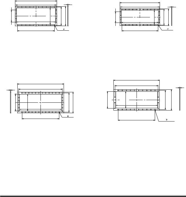
MAN B&W NA70-TO9
|
1,720 |
|
|
|
|
1,660 |
|
|
25 |
|
|
|
|
|
170 = 510 |
690 |
750 |
810 |
|
x |
1,600 |
|
|
|
3 |
|
|
|
|
|
9 x 170 = 1,530 |
28 x |
22 |
|
|
|
ABB TPL85 |
|
|
|
|
1,920 |
|
|
25 |
|
1,812 |
|
|
|
|
|
|
|
x 140 = 700 |
690 |
1,740 |
796 |
870 |
5 |
|
|
|
|
|
|
11 x 140 = 1,540 |
36 x |
30 |
Page 3 of 3
Mitsubishi MET 83/SE/SD
1,650 |
|
|
|
|
1,590 |
|
|
|
25 |
150= 450 |
580 |
640 |
700 |
|
1,530 |
|
|
|
|
3 x |
|
|
|
|
10 x 150 = 1,500 |
|
30 x |
24 |
|
|
|
ABB TPL 80 |
|
|
|
|
1,580 |
|
|
|
|
1,494 |
|
25 |
|
|
|
|
|
150 = 450 |
538 |
1,364 |
668 |
729 |
3 x |
|
|
|
|
|
|
9 x 150 = 1,350 |
28 x |
30 |
|
|
|
178 51 99-2.0
Fig. 5.10.02: List of counterflanges, turbocharger exhaust outlet (yard’s supply)
S90ME-C |
198 47 52-8.0 |