Добавил:
Upload Опубликованный материал нарушает ваши авторские права? Сообщите нам.
Вуз: Предмет: Файл:

s90mec7

.pdf
Скачиваний:
92
Добавлен:
15.02.2015
Размер:
8.14 Mб
Скачать

MAN B&W

14.07


Page of 2

Fire Extinguishing System for Scavenge Air Space

Fire in the scavenge air space can be extinguished by steam, this being the basic solution, or, optionally, by water mist or CO2.

The external system, pipe and flange connections are shown in Fig. 14.07.01 and the piping fitted onto the engine in Fig. 14.07.02.

In the Extent of Delivery, the fire extinguishing system for scavenge air space is selected by the fire extinguishing agent:

basic solution: 4 55 140 Steam

option: 4 55 142 Water mist

option: 4 55 143 CO2

The key specifications of the fire extinguishing agents are:

Steam fire extinguishing for scavenge air space

Steam pressure:

3 10 bar

Steam quantity, approx.:

7.8 kg/cyl.

Water mist fire extinguishing for scavenge air space Freshwater pressure: min. 3.5 bar Freshwater quantity, approx.: 6.3 kg/cyl.

CO2

fire extinguishing for scavenge air space

CO2

test pressure:

150 bar

CO2

quantity, approx.:

15.7 kg/cyl.

"ASICæSOLUTION æ3TEAMæEXTINGUISHING

3TEAMæPRESSURE æ ç æBAR

!4

$.æ MM

.ORMALæPOSITION

OPENæTOæBILGE

/PTION æ#/ æEXTINGUISHING #/ æTESTæPRESSURE æ æBARæ

!4

$.æ MM

/PTION æ7ATERæMISTæEXTINGUISHING

&RESHæWATERæPRESSSURE æMIN æ æBAR

!4

$.æ MM

.ORMALæPOSITION

OPENæTOæBILGE

#/ æBOTTLES

#/ æ

!TæLEASTæTWOæBOTTLESæOUGHTæTOæBEæINSTALLED )NæMOSTæCASES æONEæBOTTLEæSHOULDæBEæSUFFICIENTæ TOæEXTINGUISHæFIREæINæTHREEæCYLILNDERS æWHILEæTWOæ ORæMOREæBOTTLESæWOULDæBEæREQUIREDæTOæEXTINGUISHæ FIREæINæALLæCYLINDERS

4OæPREVENTæTHEæFIREæFROMæSPREADINGæTOæTHEæNEXT CYLINDER S æTHEæBALLçVALVEæOFæTHEæNEIGHBOURING CYLINDER S æSHOULDæBEæOPENEDæINæTHEæEVENTæOF FIREæINæONEæCYLINDER

079 61 02 9.0.0a

The letters refer to list of ‘Counterflanges’

Fig. 14.07.01: Fire extinguishing system for scavenge air space

MAN B&W S90MC-C7/8, S90ME C7/8, K90ME9, K90ME-C6/9

MAN Diesel

198 40 36 4.3


MAN B&W

14.07


Page of 2

#YL æ

4%æææ æææ)æææ!(æææ9

%XHAUSTæSIDE

-ANOEUVERINGæSIDE

%XTINGUISHINGæAGENT

#/ æ3TEAMæORæ&RESHWATER

!4

$RAINæPIPE æBEDPLATE/NLYæFORæSTEAMæORæFRESHWATER

126 40 81-0.6.0a

The letters refer to list of ‘Counterflanges’

Fig. 14.07.02: Fire extinguishing pipes in scavenge air space

MAN B&W S90MC-C7/8, S90ME C7/8, K90ME9, K90ME-C6/9

MAN Diesel

198 40 36 4.3


MAN B&W

Exhaust Gas


15

MAN Diesel

MAN B&W

15.01


Exhaust Gas System

The exhaust gas is led from the cylinders to the exhaust gas receiver where the fluctuating pressures from the cylinders are equalised and from where the gas is led further on to the turbocharger at a constant pressure. See fig. 15.01.01.

Compensators are fitted between the exhaust valve housings and the exhaust gas receiver and between the receiver and the turbocharger. A protective grating is placed between the exhaust gas receiver and the turbocharger. The turbocharger is fitted with a pick up for monitoring and remote indication of the turbocharger speed.

The exhaust gas receiver and the exhaust pipes are provided with insulation, covered by steel plating.

Page of 1

Turbochargerarrangementandcleaningsystems

The turbochargers are located on the exhaust side of the engine.

The engine is designed for the installation of the MAN Diesel turbocharger types TCA (4 59 101), ABB turbocharger type TPL (4 59 102), or MHI turbocharger type MET (4 59 103).

All makes of turbochargers are fitted with an arrangement for water washing of the compressor side, and soft blast cleaning of the turbine side, see Figs. 15.02.02, 15.02.03 and 15.02.04. Washing of the turbine side is only applicable on MAN Diesel and ABB turbochargers.

%XHAUSTæGAS RECEIVER

%XHAUSTæVALVE

4URBOCHARGER

#YLINDERæLINER

3CAVENGEæAIR RECEIVER

3CAVENGEæ

AIRæCOOLER

7ATERæMIST CATCHER

178 07 27 4.1

Fig. 15.01.01: Exhaust gas system on engine

MAN B&W K108ME C6, K98MC/ME6/7, K98MC-C/ME C6/7, S90MC-C/ME C7/8, K90MC-C/ME-C6, K90ME/ME C9, S80MC6, S80MC-C7/8, S80ME C7/8/9, K80MC-C6, K80ME C6/9, S70MC6, S70MC-C/ME C/ME GI7/8, L70MC-C/ME C7/8

MAN Diesel

198 40 47 2.3


MAN B&W

15.02


Page of 3

Exhaust Gas Pipes

4#æææ


æææ)æææ!(æææ!,æææ9(æææ9,


#YL æ


4OæSCAVENGEæAIRæRECEIVER

4)æææ 0)æææ

0)æææ

%XHAUSTæGASæRECEIVER


4URBOCHARGER

4)æææ


4#æææ æææ)æææ!(æææ9(

34æææ æææ)


&LANGEæCONNECTIONæ$


æ !, æ$EVIATIONæALARM #YLINDERæ¢ #

4)æææ

æ

9, æ$EVIATIONæALARM #YLINDERæ¢ #

The letters refer to list of ‘Counterflanges’

The item no. refer to ‘Guidance Values Automation’

121 15 27-9.2.0

Fig. 15.02.01: Exhaust gas pipes

MAN B&W K108ME C6, K98MC/ME6/7, K98MC-C/ME C6/7, S90MC-C/ME C7/8, K90MC-C/ME-C6, K90ME/ME C9, S80MC6, S80MC-C7/8, S80ME C7/8/9, K80MC-C6, K80ME C6/9, S70MC6, S70MC-C/ME C/ME GI7/8, L70MC-C/ME C7/8

MAN Diesel

198 40 70 9.2


MAN B&W

15.02


Page of 3

Cleaning Systems

!.

0)æææ


#OMPRESSORæCLEANING


-!.æ$IESELæ4#!æTURBOCHARGER


4OæBEDPLATEæDRAIN æ!%

121 15 21-8.0.0

Fig. 15.02.02: MAN Diesel TCA turbocharger, water washing of turbine side

MAN B&W MC/MC-C, ME/ME C/ME GI/ME-B engines

MAN Diesel

198 40 71 0.4


MAN B&W

15.02


Page of 3

Cleaning Systems


0)ææææ

!.


7ATERæINLET


)NLETæVALVE


$RAINæCOCK

!""æ40,æ4URBOCHARGER


#OMPRESSORæCLEANING

7ATERæCLEANINGæNOZZLE

4OæBEDPLATEæDRAIN æ!%

121 36 75-1.0.0

Fig. 15.02.03: Water washing of turbine and compressor sides for ABB, TPL turbochargers

0)ææææ

!0

$RAIN

$RYæCLEANINGæTURBINEæSIDE

3CAVENGEæAIRæRECEIVER

121 36 88-3.2.0

Fig. 15.02.04: Soft blast cleaning of turbine side

MAN B&W K108ME C6, K98MC/ME6/7, K98MC-C/ME C6/7, S90MC-C/ME C7/8, K90MC-C/ME-C6, K90ME/ME C9, S80MC6, S80MC-C7/8, S80ME C7/8/9, K80MC-C6, K80ME C6/9

MAN Diesel

198 40 72 2.3


MAN B&W

15.03


Exhaust Gas System for Main Engine

At the specified MCR of the engine, the total back pressure in the exhaust gas system after the turbocharger (as indicated by the static pressure measured in the piping after the turbocharger) must not exceed 350 mm WC (0.035 bar).

In order to have a back pressure margin for the final system, it is recommended at the design stage to initially use a value of about 300 mm WC (0.030 bar).

The actual back pressure in the exhaust gas system at specified MCR depends on the gas velocity, i.e. it is proportional to the square of the exhaust gas velocity, and hence inversely proportional to the pipe diameter to the 4th power. It has by now become normal practice in order to avoid too much pressure loss in the pipings to have an exhaust gas velocity at specified MCR of about 35 m/sec, but not higher than 50 m/sec.

For dimensioning of the external exhaust pipe connections, see the exhaust pipe diameters for 35 m/sec, 40 m/sec, 45 m/sec and 50 m/sec respectively, shown in Table 15.07.02.

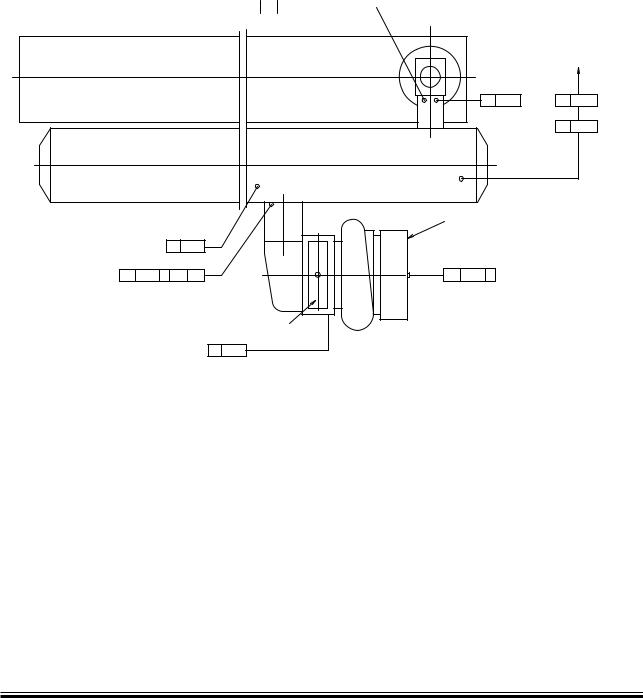
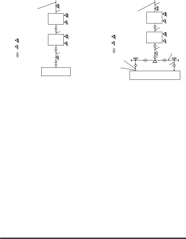
As long as the total back pressure of the exhaust gas system (incorporating all resistance losses from pipes and components) complies with the above mentioned requirements, the pressure losses across each component may be chosen independently, see proposed measuring points (M) in Fig. 15.05.01. The general design guidelines for each component, described below, can be used for guidance purposes at the initial project stage.

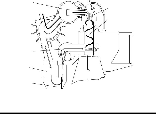
Exhaust gas piping system for main engine

The exhaust gas piping system conveys the gas from the outlet of the turbocharger(s) to the atmosphere.

The exhaust piping is shown schematically in Fig. 15.04.01.

Page of 1

The exhaust system for the main engine comprises:

Exhaust gas pipes

Exhaust gas boiler

Silencer

Spark arrester (if needed)

Expansion joints (compensators)

Pipe bracings.

In connection with dimensioning the exhaust gas piping system, the following parameters must be observed:

Exhaust gas flow rate

Exhaust gas temperature at turbocharger outlet

Maximum pressure drop through exhaust gas system

Maximum noise level at gas outlet to atmosphere

Maximum force from exhaust piping on turbocharger(s)

Sufficient axial and lateral elongation ability of expansion joints

Utilisation of the heat energy of the exhaust gas.

Items that are to be calculated or read from tables are:

Exhaust gas mass flow rate, temperature and maximum back pressure at turbocharger gas outlet

Diameter of exhaust gas pipes

Utilisation of the exhaust gas energy

Attenuation of noise from the exhaust pipe outlet

Pressure drop across the exhaust gas system

Expansion joints.

MAN B&W MC/MC C, ME/ME C/ME GI/ME-B engines

MAN Diesel

198 40 74 6.3


MAN B&W

15.04


Components of the Exhaust Gas System

%XHAUSTæGASæOUTLET

$

TOæTHEæATMOSPHERE


%XHAUSTæGASæ


SILENCER


$

3LIDEæSUPPORT

%XHAUSTæGASæ

BOILER


&IXEDæSUPPORT


$

%XHAUSTæGASæCOMPENSATOR


-AINæENGINEæWITH


TURBOCHARGERæONæAFTæEND

178 42 78 3.2

Fig. 15.04.01a: Exhaust gas system, one turbocharger

Exhaust gas compensator after turbocharger

When dimensioning the compensator (option:

4 60 610) for the expansion joint on the turbocharger gas outlet transition piece (option: 4 60 601) the exhaust gas piece and components, are to be so arranged that the thermal expansions are absorbed by expansion joints. The heat expansion of the pipes and the components is to be calculated based on a temperature increase from 20 °C to 250 °C. The max. expected vertical, transversal and longitudinal heat expansion of the engine measured at the top of the exhaust gas transition piece of the turbocharger outlet are indicated in Fig. 15.06.01 and Table 15.06.02 as DA, DB and DC.

The movements stated are related to the engine seating, for DC, however, to the engine centre. The figures indicate the axial and the lateral movements related to the orientation of the expansion joints.

The expansion joints are to be chosen with an elasticity that limits the forces and the moments of the exhaust gas outlet flange of the turbocharger as stated for each of the turbocharger makers in Table 15.06.04. The orientation of the maximum permissible forces and moments on the gas outlet flange of the turbocharger is shown in Fig. 15.06.03.

Page of 2


$


%XHAUSTæGASæOUTLET


TOæTHEæATMOSPHERE


%XHAUSTæGASæ


SILENCER


$


3LIDEæSUPPORT

%XHAUSTæGASæ


BOILER


&IXEDæSUPPORT

$


%XHAUSTæGASæCOMPENSATOR

$


4RANSITIONæPIECE


4URBOCHARGERæGAS

$


OUTLETæFLANGE


-AINæENGINEæWITHæTURBOCHARGERS


ONæEXHAUSTæSIDE


178 33 46 7.4

Fig. 15.04.01b: Exhaust gas system, two or more TCs

Exhaust gas boiler

Engine plants are usually designed for utilisation of the heat energy of the exhaust gas for steam production or for heating the thermal oil system. The exhaust gas passes an exhaust gas boiler which is usually placed near the engine top or in the funnel.

It should be noted that the exhaust gas temperature and flow rate are influenced by the ambient conditions, for which reason this should be considered when the exhaust gas boiler is planned. At specified MCR, the maximum recommended pressure loss across the exhaust gas boiler is normally 150 mm WC.

This pressure loss depends on the pressure losses in the rest of the system as mentioned above. Therefore, if an exhaust gas silencer/spark arrester is not installed, the acceptable pressure loss across the boiler may be somewhat higher than the max. of 150 mm WC, whereas, if an exhaust gas silencer/spark arrester is installed, it may be necessary to reduce the maximum pressure loss.

The above mentioned pressure loss across the exhaust gas boiler must include the pressure losses from the inlet and outlet transition pieces.

MAN B&W MC/MC C, ME/ME C/ME GI/ME-B engines

MAN Diesel

198 40 75 8.6


Соседние файлы в предмете [НЕСОРТИРОВАННОЕ]