

s90mec7
.pdfMAN B&W Diesel A/S |
|
|
|
|
6.03 |
|||
|
|
|
|
|
|
|
|
|
|
|
|
|
|
|
|
Page 1 of 3 |
|
List of capacities, S90ME-C, High efficiency T/C and seawater cooling system |
||||||||
|
|
|
|
|
|
|
||
|
|
Cyl. |
6 |
7 |
8 |
9 |
||
|
|
|
|
|
|
|
||
|
Nominal MCR at 76.0 r/min |
kW |
29,340 |
34,230 |
39,120 |
44,010 |
||
|
Fuel oil circulating pump |
m3/h |
|
11.5 |
13.5 |
15.4 |
17.3 |
|
|
Fuel oil supply pump |
m3/h |
|
7.2 |
8.4 |
9.6 |
10.8 |
|
|
Jacket cooling pump |
m3/h |
1) |
230 |
270 |
305 |
345 |
|
|
|
|
2) |
250 |
285 |
335 |
370 |
|
Pumps |
|
|
3) |
230 |
270 |
305 |
345 |
|
|
|
4) |
230 |
270 |
305 |
345 |
||
|
|
|
||||||
|
Seawater cooling pump* |
m3/h |
1) |
860 |
1,010 |
1,150 |
1,290 |
|
|
|
|
2) |
870 |
1,020 |
1,170 |
1,310 |
|
|
|
|
3) |
870 |
1,010 |
1,150 |
1,300 |
|
|
|
|
4) |
860 |
1,010 |
1,150 |
1,290 |
|
|
Main lubricating oil pump* |
m3/h |
1) |
550 |
640 |
730 |
820 |
|
|
|
|
2) |
550 |
640 |
740 |
820 |
|
|
|
|
3) |
560 |
640 |
730 |
820 |
|
|
|
|
4) |
550 |
640 |
730 |
820 |
|
|
Scavenge air cooler(s): |
|
|
|
|
|
|
|
|
Heat dissipation approx. |
kW |
|
11,400 |
13,290 |
15,190 |
17,090 |
|
|
Seawater flow |
m3/h |
|
558 |
651 |
744 |
837 |
|
|
Lubricating oil cooler: |
|
|
|
|
|
|
|
|
Heat dissipation approx.* |
kW |
1) |
2,220 |
2,610 |
2,940 |
3,270 |
|
|
|
|
2) |
2,280 |
2,610 |
3,090 |
3,420 |
|
|
|
|
3) |
2,380 |
2,710 |
3,040 |
3,420 |
|
|
|
|
4) |
2,220 |
2,610 |
2,940 |
3,330 |
|
Coolers |
Lubricating oil flow* |
m3/h |
|
|
See above ‘Main lubricating oil pump’ |
|
||
Seawater flow |
m3/h |
1) |
302 |
359 |
406 |
453 |
||
|
||||||||
|
|
|
2) |
312 |
369 |
426 |
473 |
|
|
|
|
3) |
312 |
359 |
406 |
463 |
|
|
|
|
4) |
302 |
359 |
406 |
453 |
|
|
|
|
|
|
|
|
|
|
|
Jacket water cooler: |
|
|
|
|
|
|
|
|
Heat dissipation approx. |
kW |
1) |
3,960 |
4,620 |
5,280 |
5,940 |
|
|
|
|
2) |
4,120 |
4,780 |
5,520 |
6,180 |
|
|
|
|
3) |
3,960 |
4,620 |
5,280 |
5,940 |
|
|
|
|
4) |
3,960 |
4,620 |
5,280 |
5,940 |
|
|
|
|
|
|
|
|
|
|
|
Jacket cooling water flow |
m3/h |
|
|
See above ‘Jacket cooling water’ |
|
||
|
Seawater flow |
m3/h |
|
|
See above ‘Seawater quantity’ |
|
||
|
Fuel oil heater |
kW |
|
300 |
355 |
405 |
455 |
|
|
Exhaust gas amount at 245º C** kg/h |
|
268,800 |
313,600 |
358,400 |
403,200 |
||
|
|
|
|
|
|
|
|
|
|
Air consumption |
kg/s |
|
73.3 |
85.5 |
97.7 |
110.0 |
|
|
|
|
|
|
|
|
|
|
*For main engine arrangements with built-on power take-off (PTO) of an MAN B&W recommended type and/or torsional vibration damper the engine’s capacities must be increased by those stated for the actual system
** The exhaust gas amount and temperature must be adjusted according to the actual plant specification
1) |
Engines with MAN B&W turbochargers, type TCA |
3) |
Engines with ABB turbochargers, type TPL |
2) |
Engines with MAN B&W turbochargers, type NA |
4) |
Engines with Mitsubishi turbochargers |
Fig. 6.03.01: High efficiency turbocharger and seawater cooling system stated at the nominal MCR power (L1) for engines complying with IMO’s NOx emission limitations
S90ME-C |
198 43 43-1.1 |

MAN B&W Diesel A/S |
6.03 |
|
|
|
Page 2 of 3 |
List of capacities, S90ME-C, High efficiency T/C and central water cooling system
|
|
|
Cyl. |
6 |
|
7 |
8 |
|
9 |
|
|
Nominal, |
MCR at 76.0 r/min |
kW |
29,340 |
|
34,230 |
39,120 |
|
44,010 |
|
|
Fuel oil circulating pump |
m3/h |
|
11.5 |
|
13.5 |
15.4 |
|
17.3 |
|
|
Fuel oil supply pump |
m3/h |
|
7.2 |
|
8.4 |
9.6 |
|
10.8 |
|
|
Jacket cooling pump |
m3/h |
1) |
230 |
|
270 |
305 |
|
345 |
|
|
|
|
|
2) |
250 |
|
285 |
335 |
|
370 |
|
|
|
|
3) |
230 |
|
270 |
305 |
|
345 |
|
|
|
|
4) |
230 |
|
270 |
305 |
|
345 |
|
Central cooling pump* |
m3/h |
1) |
670 |
|
790 |
900 |
|
1,010 |
|
Pumps |
|
|
|
2) |
680 |
|
790 |
920 |
|
1,030 |
|
|
|
4) |
670 |
|
790 |
900 |
|
1,010 |
|
|
|
|
|
3) |
680 |
|
790 |
900 |
|
1,010 |
|
Seawater cooling pump* |
m3/h |
1) |
860 |
|
1,010 |
1,150 |
|
1,290 |
|
|
|
|
|
2) |
870 |
|
1,010 |
1,170 |
|
1,310 |
|
|
|
|
3) |
870 |
|
1,010 |
1,150 |
|
1,300 |
|
|
|
|
4) |
860 |
|
1,010 |
1,150 |
|
1,290 |
|
Main lubricating oil pump* |
m3/h |
1) |
550 |
|
640 |
730 |
|
820 |
|
|
|
|
|
2) |
550 |
|
640 |
740 |
|
820 |
|
|
|
|
3) |
560 |
|
640 |
730 |
|
820 |
|
|
|
|
4) |
550 |
|
640 |
730 |
|
820 |
|
Scavenge air cooler(s): |
|
|
|
|
|
|
|
|
|
|
Heat dissipation approx. |
kW |
|
11,310 |
|
13,200 |
15,080 |
|
16,970 |
|
|
Seawater flow |
m3/h |
|
378 |
|
441 |
504 |
|
567 |
|
|
Lubricating oil cooler: |
|
|
|
|
|
|
|
|
|
|
Heat dissipation approx.* |
kW |
1) |
2,220 |
|
2610 |
2,940 |
|
3,270 |
|
|
|
|
|
2) |
2,280 |
|
2610 |
3,090 |
|
3,420 |
|
|
|
|
3) |
2,380 |
|
2710 |
3,040 |
|
3,420 |
|
|
|
|
4) |
2,220 |
|
2610 |
2,940 |
|
3,330 |
|
Lubricating oil flow |
m3/h |
|
|
|
See above ‘Main lubricating oil pump’ |
|
|||
|
Central cooling water flow |
m3/h |
1) |
292 |
|
349 |
396 |
|
443 |
|
|
|
|
|
2) |
302 |
|
349 |
416 |
|
463 |
|
|
|
|
3) |
302 |
|
349 |
396 |
|
443 |
|
|
|
|
4) |
292 |
|
349 |
396 |
|
443 |
Coolers |
Jacket water cooler: |
|
|
|
|
|
|
|
|
|
Heat dissipation approx. |
kW |
1) |
3,960 |
|
4,620 |
5,280 |
|
5,940 |
||
|
|
|
||||||||
|
|
|
|
2) |
4,120 |
|
4,780 |
5,520 |
|
6,180 |
|
|
|
|
3) |
3,960 |
|
4,620 |
5,280 |
|
5,940 |
|
|
|
|
4) |
3,960 |
|
4,620 |
5,280 |
|
5,940 |
|
Jacket cooling water flow |
m3/h |
|
|
|
See above ‘Jacket cooling water’ |
|
|||
|
Central cooling water flow |
m3/h |
|
See above ‘Central cooling water quantity’ for lube oil |
||||||
|
Central cooler: |
|
|
|
|
|
|
|
|
|
|
Heat dissipation approx.* |
kW |
1) |
17,490 |
|
20,430 |
23,300 |
|
26,180 |
|
|
|
|
|
2) |
17,710 |
|
20,590 |
23,690 |
|
26,570 |
|
|
|
|
3) |
17,650 |
|
20,530 |
23,400 |
|
26,330 |
|
|
|
|
4) |
17,490 |
|
20,430 |
23,300 |
|
26,240 |
|
Central cooling water flow |
m3/h |
|
|
|
|
|
|
|
|
|
|
|
|
See above ‘Central |
cooling water pump’ |
|
|
|||
|
Seawater flow |
m3/h |
|
|
|
See above ‘Seawater cooling pump’ |
|
|||
|
Fuel oil heater |
kW |
|
300 |
|
355 |
405 |
|
455 |
|
|
Exhaust gas amount at 245º C** kg/h |
|
268,800 |
|
313,600 |
358,400 |
|
403,200 |
||
|
Air consumption |
kg/s |
|
73.3 |
|
85.5 |
97.7 |
|
110.0 |
|
|
|
|
|
|
|
|
|
|
|
|
Fig. 6.03.02: High efficiency turbocharger and central cooling water system stated at the nominal MCR power (L1) for engines complying with IMO’s NOx emission limitations
S90ME-C |
198 43 43-1.1 |

MAN B&W Diesel A/S |
6.03 |
|
|
Page 3 of 3
Capacities of starting air receivers and compressors for S90ME-C
Starting air system: 30 bar (gauge)
Cylinder No. |
|
6 |
7 |
8 |
9 |
|
|
|
|
|
|
Reversible engine, 12 starts |
|
|
|
|
|
|
|
|
|
|
|
Receiver volume |
m3 |
2 x 15.0 |
2 x 15.0 |
2 x 15.5 |
2 x 15.5 |
Compressor capacity, total |
Nm3/h |
900 |
900 |
930 |
930 |
Non-reversible engine, 6 starts |
|
|
|
|
|
|
|
|
|
|
|
Receiver volume |
m3 |
2 x 8.0 |
2 x 8.0 |
2 x 8.0 |
2 x 8.0 |
Compressor capacity, total |
Nm3/h |
480 |
480 |
480 |
480 |
|
|
|
|
|
|
178 45 67-7.1
Fig.: 6.03.03: Capacities of starting air receivers and compressors for main engine S90ME-C
S90ME-C |
198 43 43-1.1 |
MAN B&W Diesel A/S |
6.04 |
|
|
Auxiliary Machinery Capacities
The dimensioning of heat exchangers (coolers) and pumps for derated engines can be calculated on the basis of the heat dissipation values found by using the following description and diagrams. Those for the nominal MCR (L1), may also be used if wanted.
The nomenclature of the basic engine ratings and coolers, etc. used in this section is shown in Fig. 6.01.01 and 6.01.02.
Cooler heat dissipations
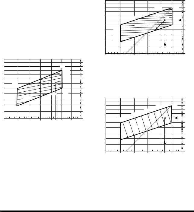
For the specified MCR (M) the following three diagrams in Figs. 6.04.01, 6.04.02 and 6.04.03 show reduction factors for the corresponding heat dissipations for the coolers, relative to the values stated in the ‘List of Capacities’ valid for nominal MCR (L1).
Specified MCR power, % of L1
PM%
|
|
|
|
|
L1 |
|
110% |
|
|
|
|
|
|
|
|
|
|
|
|
|
100% |
|
100% |
|
|
|
|
|
|
|
|
|
|
|
|
|
90% |
|
|
|
|
|
|
M |
80% |
|
90% |
|
L3 |
|
|
|
|
||
|
|
|
|
|
|
||
|
|
|
|
70% |
|
80% |
|
|
|
|
|
|
L2 |
|
|
|
|
Qair% |
|
60% |
|
|
|
|
|
|
|
|
|
70% |
|
|
|
55% |
|
|
|
|
|
|
L4 |
|
|
|
|
|
60% |
|
|
|
|
|
|
|
|
75% |
80% |
85% |
90% |
95% |
100% |
105% |
110% nM% |
|
|
|
Specified MCR engine speed, % of L1 |
||||
178 50 93-6.0
Qair% = 100 x (PM/PL1)1.68 x (nM/nL1) – 0.83 x kO
kO = 1 + 0.27 x (1 – PO/PM)
Fig. 6.04.01: Scavenge air cooler, heat dissipation Qair% in
point M, in % of the L1 value Qair, L1and valid for PO = PM. If matching point O lower than M, an extra correction kO
is used
Page 1 of 12
The percentage power (PM%) and speed (nM%) of L1 e: PM% = PM/PL1 x 100%
nM% = nM/nL1 x 100%
for specified MCR (M) of the derated engine is used as input in the above-mentioned diagrams, giving the % heat dissipation figures relative to those in the ‘List of Capacities’,
Specified MCR power, % af L1 PM%
|
|
|
|
|
|
110% |
|
|
|
|
98% |
L1 |
100% |
|
|
|
|
|
|
|
|
|
|
94% |
|
|
90% |
|
|
90% |
|
|
M |
|
|
|
|
|
|
||
|
86% |
Qjw% |
|
|
|
80% |
|
|
|
O |
|
||
|
82% |
|
|
|
|
|
|
|
|
|
|
|
|
|
78% |
|
|
|
|
70% |
|
|
|
|
|
|
|
|
74% |
|
|
|
|
|
|
72% |
|
|
|
|
|
|
|
|
|
|
|
60% |
75% |
80% |
85% |
90% |
95% |
100% |
105% nM% |
|
|
|
Specified MCR engine speed, % of L1 |
|||
178 50 94-8.0
Qjw% = e(– 0.0811 x ln (nM%) + 0.8072 x ln (PM%) + 1.2614)
Fig. 6.04.02: Jacket water cooler, heat dissipation Qjw% inpoint M, in % of the L1 value Qjw, L1
Specified MCR power, % af L1 Pm%
|
|
|
|
|
|
110% |
|
|
|
|
96% |
98% L1 |
100% |
|
|
|
|
|
||
|
|
|
|
|
|
|
|
|
|
92% |
94% |
|
|
|
|
90% |
|
|
|
|
|
|
|
|
|
90% |
|
|
|
88% |
|
|
M |
|
|
|
|
|
|
||
|
84% |
86% |
|
|
|
|
|
|
|
|
|
|
|
|
|
Qlub% |
|
|
|
80% |
|
|
|
|
|
|
|
|
|
|
|
|
|
70% |
|
82 |
|
|
|
|
|
|
|
|
|
|
|
60% |
75% |
80% |
85% |
90% |
95% |
100% |
105% nM% |
|
|
|
Specified MCR engine speed, % of L1 |
|||
178 50 96-1.0
Qlub% = 67.3009 x ln (nM%) + 7.6304 x ln (PM%) - 245.0714
Fig. 6.04.03: Lubricating oil cooler, heat dissipation Qlub% in point M, in % of the L1 value Qlub, L1
S90ME-C |
198 43 71-7.2 |

MAN B&W Diesel A/S |
6.04 |
|
|
The derated cooler capacities may then be found by means of following equations:
Qair, M |
= Qair, L1 |
x (Qair% / 100) |
Qjw, M |
= Qjw, L1 |
x (Qjw% / 100) |
Qlub, M |
= Qlub, L1 |
x (Qlub% / 100) |
and for a central cooling water system the central cooler heat dissipation is:
Qcent,M = Qair,M + Qjw,M + Qlub,M
Pump capacities
The pump capacities given in the ‘List of Capacities’ refer to engines rated at nominal MCR (L1). For lower rated engines, only a marginal saving in the pump capacities is obtainable.
To ensure proper lubrication, the lubricating oil pump must remain unchanged.
Also, the fuel oil circulating and supply pumps should remain unchanged.
In order to ensure reliable starting, the starting air compressors and the starting air receivers must also remain unchanged.
The jacket cooling water pump capacity is relatively low. Practically no saving is possible, and it is therefore unchanged.
Seawater cooling system
The derated seawater pump capacity is equal to the sum of the below found derated seawater flow capacities through the scavenge air and lube oil coolers, as these are connected in parallel.
The seawater flow capacity for each of the scavenge air, lube oil and jacket water coolers can be reduced proportionally to the reduced heat dissipations found in Figs. 6.04.01, 6.04.02 and 6.04.03, respectively i.e. as follows:
Vsw,air,M |
= |
Vsw,air,L1 |
x (Qair% / 100) |
Vsw,lub,M |
= |
Vsw,lub.L1 |
x Qlub% / 100) |
Vsw,jw,M |
= |
Vsw,lub,M |
|
However, regarding the scavenge air cooler(s), the engine maker has to approve this reduction in order
Page 2 of 12
to avoid too low a water velocity in the scavenge air cooler pipes.
As the jacket water cooler is connected in series with the lube oil cooler, the seawater flow capacity for the latter is used also for the jacket water cooler.
Central cooling water system
If a central cooler is used, the above still applies, but the central cooling water capacities are used instead of the above seawater capacities. The seawater flow capacity for the central cooler can be reduced in proportion to the reduction of the total cooler heat dissipation, i.e. as follows:
Vcw,air,M |
= Vcw,air,L |
x (Qair% / 100) |
|
1 |
|
Vcw,lub,M |
= Vcw,lub,L |
x (Qlub% / 100) |
|
1 |
|
Vcw,jw,M |
= Vcw,lub,M |
|
Vcw,cent,M |
= Vcw,air,M + Vcw,lub,M |
|
Vsw,cent,M |
= Vsw,cent,L1 x Qcent,M / Qcent,L1 |
|
Pump pressures
Irrespective of the capacities selected as per the above guidelines, the below-mentioned pump heads at the mentioned maximum working temperatures for each system shall be kept:
|
Pump |
Max. working |
|
head bar |
temp. °C |
|
|
|
Fuel oil supply pump |
4 |
100 |
|
|
|
Fuel oil circulating pump |
6 |
150 |
|
|
|
Lubricating oil pump |
4.6 |
70 |
|
|
|
Seawater pump |
2.5 |
50 |
|
|
|
Central cooling water pump |
2.5 |
80 |
|
|
|
Jacket water pump |
3.0 |
100 |
|
|
|
Flow velocities
For external pipe connections, we prescribe the following maximum velocities:
Marine diesel oil ......................................... |
1.0 m/s |
Heavy fuel oil .............................................. |
0.6 m/s |
Lubricating oil ............................................. |
1.8 m/s |
Cooling water ............................................. |
3.0 m/s |
S90ME-C, K90ME-C, S80ME-C |
198 43 81-3.1 |

MAN B&W Diesel A/S |
6.04 |
|
|
Page 3 of 12
Calculation of List of Capacities for Derated Engine
Example 1:
Pump and cooler capacities for a derated 6S90ME-C with high efficiency MAN B&W turbocharger, type TCA with fixed pitch propeller and central cooling water system.
Nominal MCR, (L1) PL1: 29,340 kW (100.0%) and 76.0 r/min (100.0%)
Specified MCR, (M) PM: 24,939 kW (85.0%) and 73.7 r/min (97.0%)
Matching point, (O) PO: 22,445 kW (76.5%) and 71.2 r/min (93.7%), PO = 90.0% of PM
The method of calculating the reduced capacities for point M (nM% = 97.0 and PM% = 85.0) is shown below.
The values valid for the nominal rated engine are found in the ‘List of Capacities’, Figs. 6.03.01 and 6.03.02, and are listed together with the result in the figure on the next page.
Heat dissipation of scavenge air cooler
Fig. 6.04.01 which approximate indicates a Qair% = 78.1% heat dissipation, and corrected for matching point O lower than M, by applying correcting factor kO, equal 78.1 x (1 + 0.27 x (1 – 0.900)) = 80.2% i.e.:
Qair,M =Qair,L1 x Qair% / 100
Qair,M = 11,310 x 0.802 = 9,071 kW
Heat dissipation of jacket water cooler
Fig. 6.04.02 indicates a Qjw% = 87.9% heat dissipation; i.e.:
Qjw,M = Qjw,L1 x Qjw% / 100
Qjw,M = 3,960 x 0.879 = 3,481 kW
Heat dissipation of lube oil cooler
Fig. 6.04.03 indicates a Qlub% = 96.7% heat dissipation; i.e.:
Qjw,M = Qjw,L1 x Qjw% / 100
Qlub,M = 2,220 x 0.967 = 2,147 kW
Central water cooler
Qcent,M = Qair,M + Qjw,M + Qlub, M
Qcent,M = 9,071 + 3,481 + 2,147 = 14,698 kW
Scavenge air coolers:
Vcw,air,M = Vcw,air,L1 x Qair% / 100
Vcw,air,M = 378 x 0.802 = 303 m3/h
Cooling water flow through lubricating oil cooler:
Vcw,lub,M = Vcw,lub,L1x Qlub% / 100
Vcw,lub,M = 292 x 0.967 = 282 m3/h
Cooling water flow through central cooler (Central cooling water pump):
Vcw,cent,M = Vcw,air,M + Vcw,lub,M
Vcw,cent,M = 303 + 282 = 586 m3/h
Cooling water flow through jacket water cooler (as for lube oil cooler):
Vcw,jw,M = Vcw,lub,M
Vcw,jw,M = 282 m3/h
Seawater pump for central cooler
As the seawater pump capacity and the central cooler heat dissipation for the nominal rated engine found in the ‘List of Capacities’ are 860 m3/h and 17,490 kW the derated seawater pump flow equals:
Seawater pump:
Vsw,cent,M = Vsw,cent,L1 xQcent,M/Qcent,L1
Vsw,cent,M = 860 x 14,698 / 17,490 = 723 m3/h
S90ME-C |
198 43 90-8.1 |

MAN B&W Diesel A/S |
|
|
6.04 |
|
|
|
|
|
|
|
Page 4 of 12 |
|
|
|
|
|
|
Nominal rated engine (L1) |
Example 1 |
|
|
high efficiency |
Specified MCR (M) |
|
|
turbochargers (TCA) |
|
|
|
|
|
Shaft power at MCR |
|
29,340 kW |
24,939 kW |
Engine speed at MCR |
|
at 76.0 r/min |
at 73.7 r/min |
Power of matching point %MCR |
|
100% |
90% |
|
|
|
|
Pumps: |
m3/h |
11.5 |
11.5 |
Fuel oil circulating pump |
|||
Fuel oil supply pump |
m3/h |
7.2 |
7.2 |
Jacket cooling water pump |
m3/h |
230 |
230 |
Central cooling water pump |
m3/h |
670 |
586 |
Seawater pump |
m3/h |
860 |
723 |
Lubricating oil pump |
m3/h |
550 |
550 |
|
|
|
|
Coolers: |
|
|
|
Scavenge air cooler |
|
|
|
Heat dissipation |
kW |
11,310 |
9,071 |
Central water quantity |
m3/h |
378 |
303 |
Lub. oil cooler |
|
|
|
Heat dissipation |
kW |
2,220 |
2,147 |
Lubricating oil quantity |
m3/h |
550 |
550 |
Central water quantity |
m3/h |
292 |
282 |
Jacket water cooler |
|
|
|
Heat dissipation |
kW |
3,960 |
3,481 |
Jacket cooling water quantity |
m3/h |
230 |
230 |
Central water quantity |
m3/h |
292 |
282 |
Central cooler |
|
|
|
Heat dissipation |
kW |
17,490 |
14,698 |
Central water quantity |
m3/h |
670 |
586 |
Seawater quantity |
m3/h |
860 |
723 |
|
|
|
|
Fuel oil heater: |
kW |
300 |
300 |
|
|
|
|
Gases at ISO ambient conditions* |
|
|
|
Exhaust gas amount |
kg/h |
268,800 |
224,961 |
Exhaust gas temperature |
°C |
245 |
238.2 |
Air consumption |
kg/sec. |
73.3 |
61.4 |
|
|
|
|
Starting air system: 30 bar (gauge) |
|
|
|
|
|
|
|
Reversible engine |
|
|
|
Receiver volume (12 starts) |
m3 |
2 x 15.0 |
2 x 15.0 |
Compressor capacity, total |
m3/h |
900 |
900 |
Non´reversible engine |
|
2 x 8.0 |
2 x 8.0 |
Receiver volume (6 starts) |
m3 |
||
Compressor capacity, total |
m3/h |
480 |
480 |
|
|
|
|
Exhaust gas tolerances: temperature –/+ 15 °C and amount +/– 5% |
|
||
|
|
|
|
The air consumption and exhaust gas figures are expected and refer to 100% specified MCR, ISO ambient reference conditions and the exhaust gas back pressure 300 mm WC
The exhaust gas temperatures refer to after turbocharger * Calculated in example 3, in this chapter
Example 1 – Capacities of derated 6S90ME-C with high efficiency MAN B&W turbocharger type TCA and central cooling water system.
S90ME-C |
198 43 90-8.1 |
MAN B&W |
6.04 |
|
|
|
Page of 12 |
Freshwater Generator
If a freshwater generator is installed and is utilising the heat in the jacket water cooling system, it should be noted that the actual available heat in the jacket cooling water system is lower than indicated by the heat dissipation figures valid for nominal MCR (L1) given in the List of Capacities. This is because the latter figures are used for dimensioning the jacket water cooler and hence incorporate a safety margin which can be needed when the engine is operating under conditions such as, e.g. overload. Normally, this margin is 10% at nominal MCR.
Calculation Method
For a derated diesel engine, i.e. an engine having a specified MCR (M) and/or a matching point (O) different from L1, the relative jacket water heat dissipation for point M and O may be found, as previously described, by means of Fig. 6.04.02.
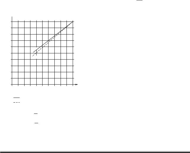
Part load correction factor for jacket cooling water heat dissipation
kp  1.0
1.0
0.9
0.8
0.7
0.6
FPP
0.
CPP
0.4
0.3
0.2
0.1
0
0 10 20 30 40 0 60 70 80 90 100% Engine load, % of matching power (O)
FPP : Fixed pitch propeller
CPP : Controllable pitch propeller, constant speed
178 06 64 3.2
FPP : kp = 0.742 x PPS + 0.258
O
CPP : kp = 0.822 x PPS + 0.178
O
Fig. 6.04.04: Correction factor ‘kp’ for jacket cooling water heat dissipation at part load, relative to heat dissipation at matching power
At part load operation, lower than matching power, the actual jacket water heat dissipation will be reduced according to the curves for fixed pitch propeller (FPP) or for constant speed, controllable pitch propeller (CPP), respectively, in Fig. 6.04.04.
With reference to the above, the heat actually available for a derated diesel engine may then be found as follows:
1.Engine power between matching and specified power.
For powers between specified MCR (M) and matching power (O), the diagram Fig. 6.04.02 is to be used, i.e. giving the percentage cor-
rection factor ‘Qjw%’ and hence for matching power PO:
Q
Qjw,O = Qjw,L1 x 100jw% x 0.9 (0.88) [1]
2.Engine power lower than matching power.
For powers lower than the matching power,
the value Qjw,O found for point O by means of the above equation [1] is to be multiplied by
the correction factor kp found in Fig. 6.04.04 and hence
|
Qjw = Qjw,O x kp 15%/0% |
[2] |
where |
|
|
Qjw |
= jacket water heat dissipation |
|
Qjw,L1= jacket water heat dissipation at nominal |
|
|
|
MCR (L1) |
|
Qjw% |
= percentage correction factor from |
|
|
Fig. 6.04.02 |
|
Qjw,O |
= jacket water heat dissipation at matching |
|
|
power (O), found by means of equation |
[1] |
kp |
= part load correction factor from Fig. 6.04.04 |
|
0.9 |
= factor for safety margin of cooler, tropical |
|
|
ambient conditions |
|
The heat dissipation is assumed to be more or less independent of the ambient temperature conditions, yet the safety margin/ambient condition factor of about 0.88 instead of 0.90 will be more accurate for ambient conditions corresponding to ISO temperatures or lower. The heat dissipation tolerance from15% to 0% stated above is based on experience.
MAN B&W ME/ME C/ME GI engines
MAN Diesel |
198 43 01 2.2 |
|
MAN B&W |
6.04 |
|
|
Page |
of 12 |
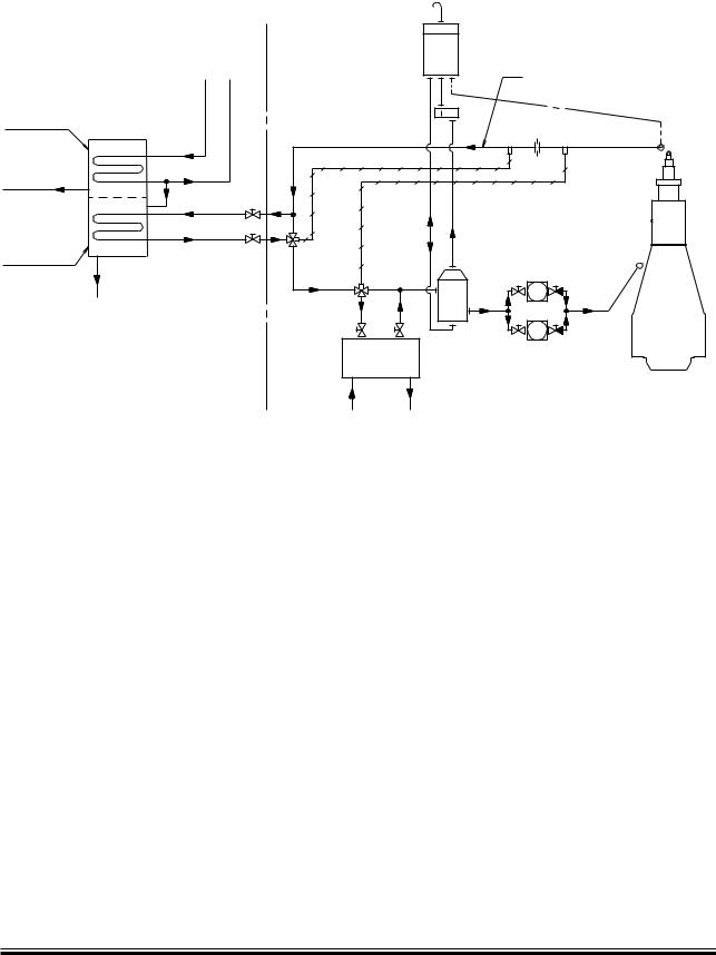
&RESHWATERæGENERATORæSYSTEM |
|
3EAWATER |
|
)N |
/UT |
#ONDENSATOR |
|
0RODUCEDæ |
|
FRESHWATER |
|
%VAPORATOR |
|
"RINEæOUT |
|
|
*ACKETæCOOLINGæWATERæSYSTEM |
|
|
|
|
%XPANSIONæTANK |
|
|
|
|
|
*ACKETæCOOLING |
|
|
|
|
WATERæCIRCUIT |
|
|
|
MIN |
MAX |
|
|
|
4JW |
4JW |
, |
- |
|
|
|||
" |
|
|
+ |
|
|
|
|
|
|
! |
|
|
|
|
|
$EAERATINGæTANK |
|
|
|
*ACKETæWATER |
*ACKETæWATERæPUMPS |
|
|
|
COOLER |
|
|
|
|
#OOLINGæ |
|
|
-AINæENGINE |
|
|
|
|
|
|
WATER |
|
|
|
|
Valve A: ensures that Tjw < 85° C
Valve B: ensures that Tjw > 85 – 5° C = 80° C
Valve B and the corresponding by pass may be omitted if, for example, the freshwater generator is equipped with an automatic start/stop function for too low jacket cooling water temperature
If necessary, all the actually available jacket cooling water heat may be utilised provided that a special temperature control system ensures that the jacket cooling water temperature at the outlet from the engine does not fall below a certain level
178 23 70 0.0
Fig. 6.04.05: Freshwater generators. Jacket cooling water heat recovery flow diagram
Jacket Cooling Water Temperature Control
When using a normal freshwater generator of the single effect vacuum evaporator type, the freshwater production may, for guidance, be estimated as 0.03 t/24h per 1 kW heat, i.e.:
Mfw = 0.03 x Qjw t/24h 15%/0% |
[3] |
where |
|
Mfw is the freshwater production in tons per 24 hours
and
Qjw is to be stated in kW
If necessary, all the actually available jacket cooling water heat may be used provided that a special temperature control system ensures that the jacket cooling water temperature at the outlet from the engine does not fall below a certain level. Such a temperature control system may consist, e.g., of a special by pass pipe installed in the jacket cooling water system, see Fig. 6.04.05, or a special built in temperature control in the freshwater generator, e.g., an automatic start/stop function, or similar.
If such a special temperature control is not applied, we recommend limiting the heat utilised to maximum 50% of the heat actually available at specified MCR, and only using the freshwater generator at engine loads above 50%. Considering the cooler margin of 10% and the minus tolerance of 15%, this heat corresponds to 50 x(1.00 0.15)x0.9 = 38%
of the jacket water cooler capacity Qjw,M used for dimensioning of the jacket water cooler.
MAN B&W ME/ME C/ME GI engines
MAN Diesel |
198 43 01 2.2 |
|

MAN B&W Diesel A/S |
6.04 |
|
|
Page 7 of 12
Calculation of Freshwater Production for Derated Engine
Example 2:
Freshwater production from a derated 6S90ME-C with high efficiency MAN B&W turbocharger of TCA type and with fixed pitch propeller.
Based on the engine ratings below, this example will show how to calculate the expected available jacket cooling water heat removed from the diesel engine, together with the corresponding freshwater production from a freshwater generator.
The calculation is made for the service rating (S) of the diesel engine being 80% of the specified MCR.
Nominal MCR, (L1) PL1: 29,340 kW (100.0%) and 76.0 r/min (100.0%)
Specified MCR, (M) PM: 24,939 kW (85.0%) and 73.7 r/min (97.0%)
Matching point, (O) PO: 22,445 kW (76.5%) and 71.2 r/min (93.7%) PO = 90.0 of PM
Service rating, (S) PS: 19,951 kW and 68.4 r/min (PS = 80.0% of PM and PS = 88.9% of PO
Ambient reference conditions: 20° C air and 18° C cooling water.
The expected available jacket cooling water heat at service rating is found as follows:
Qjw,L1 = 3,960 kW from List of Capacities
Qjw% = 81.0% using 76.5% power and 93.7% speed for O in Fig. 6.04.02
By means of equation [1], and using factor 0.88 for actual ambient condition the heat dissipation in the matching point (O) is found:
Q |
= Q |
x |
Qjw% |
x 0.88 |
|||
jw,O |
|
jw,L1 |
100 |
|
|
|
|
|
= 3,960 x |
|
81.0 |
|
x 0.88 = 2,823 kW |
||
|
100 |
|
|||||
|
|
|
|
|
|||
By means of equation [2], the heat dissipation in the service point (S) i.e. for 88.9% of matching power, is found:
kp |
= 0.918 using 88.9% in Fig. 6.05.04 |
Qjw |
= Qjw,O x kp = 2,823 x 0.918 = 2,592 kW |
|
-15%/0% |
For the service point the corresponding expected obtainable freshwater production from a freshwater generator of the single´effect vacuum evaporator type is then found from equation [3]:
Mfw = 0.03 x Qjw = 0.03 x 2,592 = 77.8 t/24h -15%/0%
S90ME-C |
198 44 07-9.1 |