

s90mec7
.pdfMAN B&W |
4.01 |
|
|
Electricity Production
Introduction
Next to power for propulsion, electricity production is the largest fuel consumer on board. The electricity is produced by using one or more of the following types of machinery, either running alone or in parrallel:
•Auxiliary diesel generating sets
•Main engine driven generators
•Exhaust gasor steam driven turbo generator utilising exhaust gas waste heat (Thermo Efficiency System)
•Emergency diesel generating sets.
The machinery installed should be selected on the basis of an economic evaluation of first cost, operating costs, and the demand for man-hours for maintenance.
In the following, technical information is given regarding main engine driven generators (PTO), different configurations with exhaust gas and steam driven turbo generators, and the auxiliary diesel generating sets produced by MAN Diesel.
Power Take Off
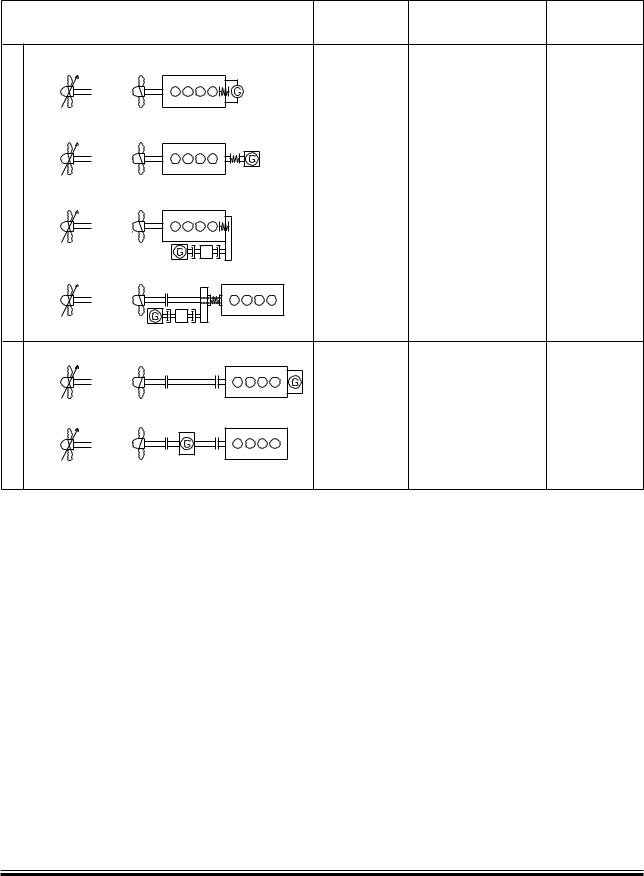
With a generator coupled to a Power Take Off (PTO) from the main engine, electrical power can be produced based on the main engine’s low SFOC and the use of heavy fuel oil. Several standardised PTO systems are available, see Fig. 4.01.01 and the designations in Fig. 4.01.02:
•PTO/RCF
(Power Take Off/Renk Constant Frequency):
Generator giving constant frequency, based on mechanical hydraulical speed control.
•PTO/CFE
(Power Take Off/Constant Frequency Electrical):
Generator giving constant frequency, based on electrical frequency control.
Page of 6
The DMG/CFE (Direct Mounted Generator/Constant Frequency Electrical) and the SMG/CFE (Shaft Mounted Generator/Constant Frequency Electrical) are special designs within the PTO/CFE group in which the generator is coupled directly to the main engine crankshaft and the intermediate shaft, respectively, without a gear. The electrical output of the generator is controlled by electrical frequency control.
Within each PTO system, several designs are available, depending on the positioning of the gear:
•BW I:
Gear with a vertical generator mounted onto the fore end of the diesel engine, without any connections to the ship structure.
•BW II:
A free standing gear mounted on the tank top and connected to the fore end of the diesel engine, with a vertical or horizontal generator.
•BW III:
A crankshaft gear mounted onto the fore end of the diesel engine, with a side mounted generator without any connections to the ship structure.
•BW IV:
A free standing step up gear connected to the intermediate shaft, with a horizontal generator.
The most popular of the gear based alternatives are the BW III/RCF type for plants with a fixed pitch propeller (FPP). The BW III/RCF requires no separate seating in the ship and only little attention from the shipyard with respect to alignment.
MAN B&W K108ME-C6, K98MC/MC-C/ME/ME-C6/7, S90MC-C/ME/ME-C7/8, K90ME/ME-C9, K90MC-C/ME-C6, S80MC6, S80MC-C7/8, S80ME-C7/8/9, K80ME-C9, K80MC-C/ME-C6
MAN Diesel |
198 41 55-0.2 |
|
MAN B&W |
4.01 |
|
|
æ æ æ
!LTERNATIVE¬TYPES¬AND¬LAYOUTS¬OF¬SHAFT¬GENERATORS¬
æ |
Aæ |
Bæ |
æ |
æ |
æ |
æ |
Aæ |
Bæ |
04/2#& |
|
|
æ |
Aæ |
Bæ |
æ |
Aæ |
Bæ |
æ |
Aæ |
Bæ |
04/#&% |
|
|
æ |
Aæ |
Bæ |
|
|
Page of 6 |
æ |
æ |
4OTAL |
$ESIGN¬ |
3EATING¬ |
¬EFFICIENCY¬ |
"7æ) 2#&æ |
/NæENGINEæ |
ç |
æVERTICALæGENERATOR
"7æ)) 2#&æ |
/NæTANKæTOPæ |
ç |
"7æ))) 2#&æ |
/NæENGINEæ |
ç |
"7æ)6 2#&æ |
/NæTANKæTOPæ |
ç |
$-' #&%æ |
/NæENGINEæ |
ç |
3-' #&%æ |
/NæTANKæTOPæ |
ç |
178 57 12-1.0
Fig. 4.01.01: Types of PTO
MAN B&W K108ME-C6, K98MC/MC-C/ME/ME-C6/7, S90MC-C/ME/ME-C7/8, K90ME/ME-C9, K90MC-C/ME-C6, S80MC6, S80MC-C7/8, S80ME-C7/8/9, K80ME-C9, K80MC-C/ME-C6
MAN Diesel |
198 41 55-0.2 |
|
MAN B&W |
4.01 |
|
|
|
Page of 6 |
Designation of PTO
For further information, please refer to our publication titled:
Shaft Generators for MC and ME engines
The publication is available at: www.mandiesel.com under ‘Quicklinks’ → ‘Technical Papers’
178 06 49 0.0
Power take off:
BW III S90ME C7/RCF 700 60
50: 50 Hz
60: 60 Hz
kW on generator terminals
RCF: Renk constant frequency unit
CFE: Electrically frequency controlled unit
Mark version
Engine type on which it is applied
Layout of PTO: See Fig. 4.01.01
Make: MAN Diesel
178 39 55 6.0
Fig. 4.01.02: Example of designation of PTO
MAN B&W K108ME-C6, K98ME/ME-C6/7, S90ME/ME-C7/8, K90ME/ME-C9, K90ME-C6, S80ME-C7/8/9, K80ME-C9, K80ME-C6
MAN Diesel |
198 42 86 7.3 |
|
MAN B&W |
4.01 |
|
|
|
Page of 6 |
PTO/RCF
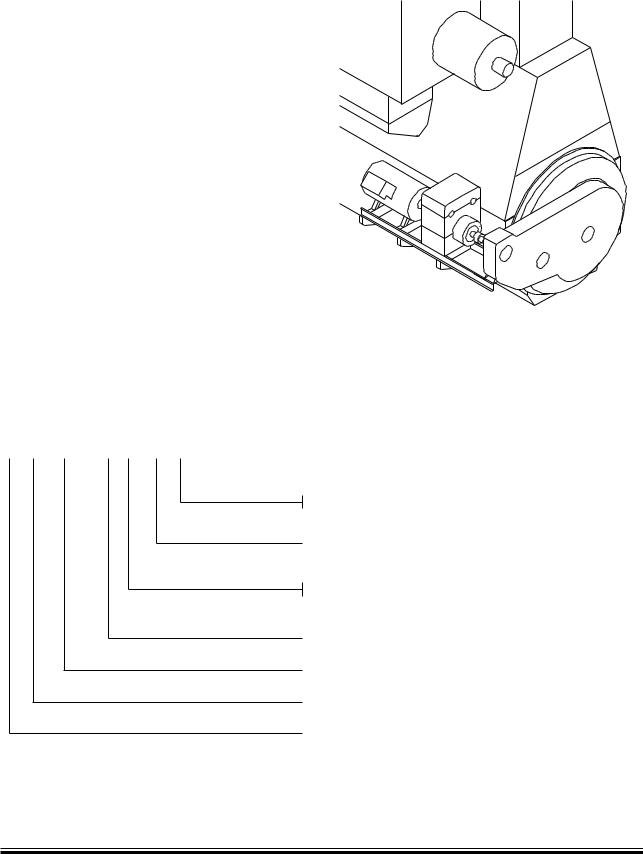
Side mounted generator, BWIII/RCF (Fig. 4.01.01, Alternative 3)
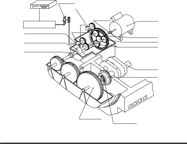
The PTO/RCF generator systems have been developed in close cooperation with the German gear manufacturer RENK. A complete package solution is offered, comprising a flexible coupling, a step up gear, an epicyclic, variable ratio gear with built in clutch, hydraulic pump and motor, and a standard generator, see Fig. 4.01.03.
For marine engines with controllable pitch propellers running at constant engine speed, the hydraulic system can be dispensed with, i.e. a PTO/GCR design is normally used.
Fig. 4.01.03 shows the principles of the PTO/RCF arrangement. As can be seen, a step up gear box (called crankshaft gear) with three gear wheels
is bolted directly to the frame box of the main engine. The bearings of the three gear wheels are mounted in the gear box so that the weight of the wheels is not carried by the crankshaft. In the frame box, between the crankcase and the gear drive, space is available for tuning wheel, counterweights, axial vibration damper, etc.
The first gear wheel is connected to the crankshaft via a special flexible coupling made in one piece with a tooth coupling driving the crankshaft gear, thus isolating it against torsional and axial vibrations.
By means of a simple arrangement, the shaft in the crankshaft gear carrying the first gear wheel and the female part of the toothed coupling can be moved forward, thus disconnecting the two parts of the toothed coupling.
/PERATINGæPANEL
INæSWITCHBOARD
3ERVOæVALVE
(YDROSTATICæMOTOR |
|
4OOTHED |
|
COUPLING |
'ENERATOR |
2#ONTROLLER |
|
(YDROSTATICæPUMP |
|
|
!NNULUSæRING |
-ULTIDISCæCLUTCH |
3UNæWHEEL |
|
0LANETARYæGEARæWHEEL |
4OOTHEDæCOUPLING |
|
#RANKSHAFT
%LASTICæDAMPINGæCOUPLING
#RANKSHAFTæGEAR
4OOTHEDæCOUPLING
178 23 22 2.1
Fig. 4.01.03: Power take off with RENK constant frequency gear: BW III/RCF, option: 4 85 253
MAN B&W K108ME-C6, K98MC/MC-C/ME/ME-C6/7, S90MC-C/ME-C7/8, K90ME/ME-C9, K90MC-C/ME-C6, S80MC6, S80MC-C7/8, S80ME-C7/8/9, K80ME-C9, K80MC-C/ME-C6, S70MC C/ME-C/ME-GI7/8, L70MC C/ME-C7/8, S70MC6, S65ME-C/ME-GI8, S60MC6, S60MC-C/ME-C/ME-GI7/8, L60MC-C/ME-C7/8, S50MC-C/ME-C7/8, S50MC6, S50ME-B8/9
MAN Diesel |
198 43 00 0.2 |
|

MAN B&W |
4.01 |
|
|
The power from the crankshaft gear is transferred, via a multi disc clutch, to an epicyclic variable ratio gear and the generator. These are mounted on a common bedplate, bolted to brackets integrated with the engine bedplate.
The BWIII/RCF unit is an epicyclic gear with a hydrostatic superposition drive. The hydrostatic input drives the annulus of the epicyclic gear in either direction of rotation, hence continuously varying the gearing ratio to keep the generator speed constant throughout an engine speed variation of 30%. In the standard layout, this is between 100% and 70% of the engine speed at specified MCR, but it can be placed in a lower range if required.
The input power to the gear is divided into two paths – one mechanical and the other hydrostatic
– and the epicyclic differential combines the power of the two paths and transmits the combined power to the output shaft, connected to the generator. The gear is equipped with a hydrostatic motor driven by a pump, and controlled by an electronic control unit. This keeps the generator speed constant during single running as well as when running in parallel with other generators.
The multi disc clutch, integrated into the gear input shaft, permits the engaging and disengaging of the epicyclic gear, and thus the generator, from the main engine during operation.
An electronic control system with a RENK controller ensures that the control signals to the main electrical switchboard are identical to those for the normal auxiliary generator sets. This applies to ships with automatic synchronising and load sharing, as well as to ships with manual switchboard operation.
Internal control circuits and interlocking functions between the epicyclic gear and the electronic control box provide automatic control of the functions necessary for the reliable operation and protection of the BWIII/RCF unit. If any monitored value exceeds the normal operation limits, a warning or an alarm is given depending upon the origin, severity and the extent of deviation from the permissible values. The cause of a warning or an alarm is shown on a digital display.
Page of 6
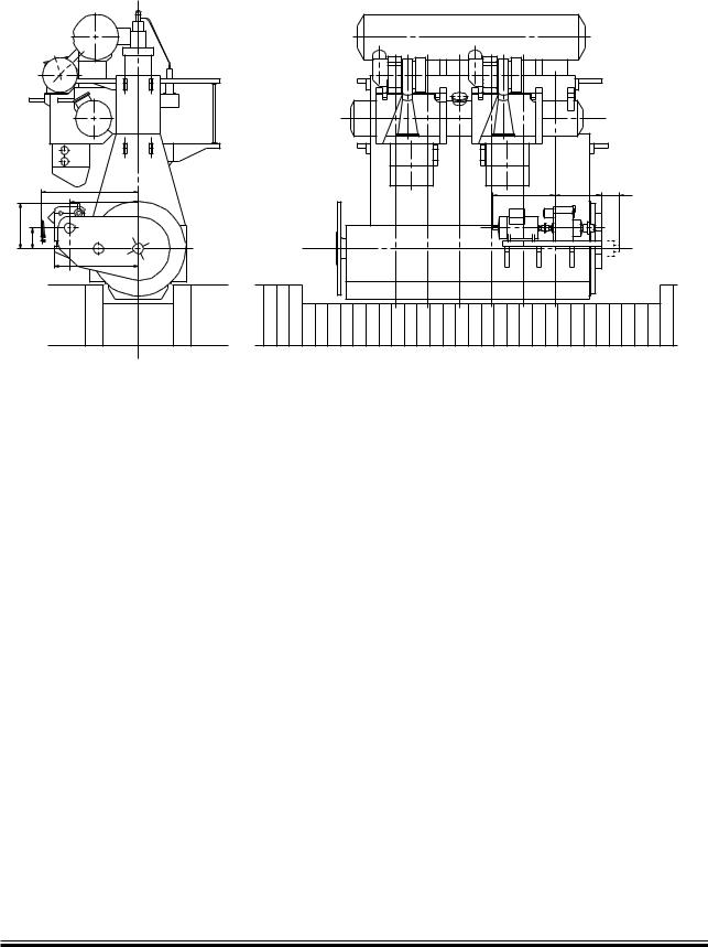
Extent of delivery for BWIII/RCF units
The delivery comprises a complete unit ready to be built on to the main engine. Fig. 4.02.01 shows the required space and the standard electrical output range on the generator terminals.
Standard sizes of the crankshaft gears and the RCF units are designed for:
700, 1200, 1800 and 2600 kW, while the generator sizes of make A. van Kaick are:
Type |
|
440 V |
60 Hz |
380 V |
50 Hz |
|
1800 |
r/min |
1500 |
r/min |
|
DSG |
|
||||
|
kVA |
kW |
kVA |
kW |
|
|
|
||||
|
|
|
|
|
|
62 |
M2 4 |
707 |
566 |
627 |
501 |
62 |
L1 4 |
855 |
684 |
761 |
609 |
62 |
L2 4 |
1,056 |
845 |
940 |
752 |
74 |
M1 4 |
1,271 |
1,017 |
1,137 |
909 |
74 |
M2 4 |
1,432 |
1,146 |
1,280 |
1,024 |
74 |
L1 4 |
1,651 |
1,321 |
1,468 |
1,174 |
74 |
L2 4 |
1,924 |
1,539 |
1,709 |
1,368 |
86 |
K1 4 |
1,942 |
1,554 |
1,844 |
1,475 |
86 |
M1 4 |
2,345 |
1,876 |
2,148 |
1,718 |
86 |
L2 4 |
2,792 |
2,234 |
2,542 |
2,033 |
99 |
K1 4 |
3,222 |
2,578 |
2,989 |
2,391 |
|
|
|
|
|
178 34 89 3.1 |
In the event that a larger generator is required, please contact MAN Diesel.
If a main engine speed other than the nominal is required as a basis for the PTO operation, it must be taken into consideration when determining the ratio of the crankshaft gear. However, it has no influence on the space required for the gears and the generator.
The PTO can be operated as a motor (PTI) as well as a generator by making some minor modifications.
MAN B&W K108ME-C6, K98MC/MC-C/ME/ME-C6/7, S90MC-C/ME-C7/8, K90ME/ME-C9, K90MC-C/ME-C6, S80MC6, S80MC-C7/8, S80ME-C7/8/9, K80ME-C9, K80MC-C/ME-C6, S70MC C/ME-C/ME-GI7/8, L70MC C/ME-C7/8, S70MC6, S65ME-C/ME-GI8, S60MC6, S60MC-C/ME-C/ME-GI7/8, L60MC-C/ME-C7/8, S50MC-C/ME-C7/8, S50MC6, S50ME-B8/9
MAN Diesel |
198 43 00 0.2 |
|

MAN B&W |
4.01 |
|
|
Yard deliveries are:
1.Cooling water pipes to the built on lubricating oil cooling system, including the valves.
2.Electrical power supply to the lubricating oil stand by pump built on to the RCF unit.
3.Wiring between the generator and the operator control panel in the switchboard.
4.An external permanent lubricating oil filling up connection can be established in connection with the RCF unit. The system is shown in Fig. 4.03.03 ‘Lubricating oil system for RCF gear’. The dosage tank and the pertaining piping are to be delivered by the yard. The size of the dosage tank is stated in the table for RCF gear in ‘Necessary capacities for PTO/RCF’ (Fig. 4.03.02).
The necessary preparations to be made on the engine are specified in Figs. 4.03.01a and 4.03.01b.
Page of 6
Additional capacities required for BWIII/RCF
The capacities stated in the ‘List of capacities’ for the main engine in question are to be increased by the additional capacities for the crankshaft gear and the RCF gear stated in Fig. 4.03.02.
MAN B&W K108ME-C6, K98MC/MC-C/ME/ME-C6/7, S90MC-C/ME-C7/8, K90ME/ME-C9, K90MC-C/ME-C6, S80MC6, S80MC-C7/8, S80ME-C7/8/9, K80ME-C9, K80MC-C/ME-C6, S70MC C/ME-C/ME-GI7/8, L70MC C/ME-C7/8, S70MC6, S65ME-C/ME-GI8, S60MC6, S60MC-C/ME-C/ME-GI7/8, L60MC-C/ME-C7/8, S50MC-C/ME-C7/8, S50MC6, S50ME-B8/9
MAN Diesel |
198 43 00 0.2 |
|
MAN B&W |
4.02 |
|
|
|
Page of 1 |
$ |
! |
& |
" |
# |
( |
' |
3 |
178 36 29-6.1
|
|
|
kW generator |
|
|
|
|
|
|
|
|
|
700 kW |
1200 kW |
|
1800 kW |
2600 kW |
|
|
|
|
|
|
A |
3,342 |
3,342 |
|
3,482 |
3,482 |
|
|
|
|
|
|
B |
623 |
623 |
|
623 |
623 |
|
|
|
|
|
|
C |
4,002 |
4,002 |
|
4,282 |
4,282 |
|
|
|
|
|
|
D |
4,294 |
4,294 |
|
4,574 |
4,574 |
|
|
|
|
|
|
F |
1,673 |
1,793 |
|
1,913 |
2,023 |
|
|
|
|
|
|
G |
3,029 |
3,029 |
|
3,389 |
3,389 |
|
|
|
|
|
|
H |
1,449 |
1,951 |
|
2,326 |
3,656 |
|
|
|
|
|
|
S |
430 |
530 |
|
620 |
710 |
|
|
|
|
|
|
|
|
System mass (kg) with generator: |
|
||
|
|
|
|
|
|
|
36,250 |
41,500 |
|
55,100 |
71,550 |
|
|
|
|
|
|
|
|
System mass (kg) without generator: |
|
||
|
|
|
|
|
|
|
34,250 |
38,850 |
|
50,800 |
66,350 |
|
|
|
|
|
|
The stated kW at the generator terminals is available between 70% and 100% of the engine speed at specified MCR
Space requirements have to be investigated case by case on plants with 2600 kW generator.
Dimension H: This is only valid for A. van Kaick generator type DSG, enclosure IP23, frequency = 60 Hz, speed = 1800 r/min
Fig. 4.02.01: Space requirement for side mounted generator PTO/RCF type BWlll S90 C/RCF
MAN B&W S90MC-C/ME-C7/8
MAN Diesel |
198 43 04-8.1 |
MAN B&W |
4.03 |
|
|
|
Page of 6 |
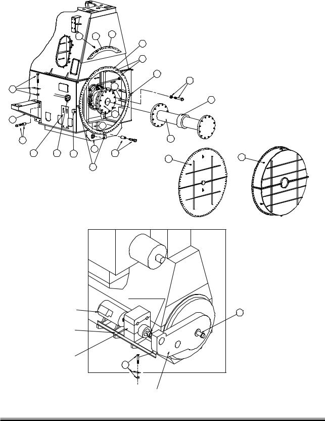
Engine preparations for PTO
|
|
|
|
|
|
|
|
|
|
||
|
|
|
|
|
|
|
|
|
|
|
|
|
|
|
|
|
|
|
|
|
|
|
|
|
|
|
|
|
|
|
|
|
|
|
|
|
|
|
|
|
|
|
|
|
|
|
|
|
|
|
|
|
|
|
|
|
|
|
|
|
|
|
|
|
|
|
|
|
|
|
|
|
|
|
|
|
|
|
|
|
|||
|
|
|
|
|
|
|
|
|
|
|
|
|
|
|
|
|
|
4OOTHEDæCOUPLING |
!LTERNATOR |
|
"EDFRAME |
2#&GEAR |
IFæORDERED |
|
#RANKSHAFTæGEAR |
Fig. 4.03.01a: Engine preparations for PTO
S90MC-C/ME-C7/8, K90ME/ME-C9, K90MC-C/ME-C6, S80MC6, |
MAN Diesel |
MAN B&W K108ME-C6, K98MC/MC-C/ME/ME-C6/7, |
|
S80MC-C7/8, S80ME-C7/8/9, K80ME-C9, K80MC-C/ME-C6, |
|
S70MC C/ME-C/ME-GI7/8, S70MC6, L70MC C/ME-C7/8, |
|
S65ME-C/ME-GI8, S60MC6, S60MC-C/ME-C/ME-GI7/8, |
|
L60MC-C/ME-C7/8, S50MC-C7/8, S50MC6, S50ME-B8/9 |
|
178 57 15-7.0
198 43 15 6.2

MAN B&W |
4.03 |
|
|
|
Page of 6 |
Pos.
1Special face on bedplate and frame box
2Ribs and brackets for supporting the face and machined blocks for alignment of gear or stator housing
3 Machined washers placed on frame box part of face to ensure that it is flush with the face on the bedplate
4Rubber gasket placed on frame box part of face
5 Shim placed on frame box part of face to ensure that it is flush with the face of the bedplate
6Distance tubes and long bolts
7 Threaded hole size, number and size of spring pins and bolts to be made in agreement with PTO maker 8 Flange of crankshaft, normally the standard execution can be used
9Studs and nuts for crankshaft flange
10Free flange end at lubricating oil inlet pipe (incl. blank flange)
11Oil outlet flange welded to bedplate (incl. blank flange)
12Face for brackets
13Brackets
14Studs for mounting the brackets
15Studs, nuts and shims for mounting of RCF /generator unit on the brackets
16Shims, studs and nuts for connection between crankshaft gear and RCF /generator unit
17Engine cover with connecting bolts to bedplate/frame box to be used for shop test without PTO
18Intermediate shaft between crankshaft and PTO
19Oil sealing for intermediate shaft
20Engine cover with hole for intermediate shaft and connecting bolts to bedplate/frame box
21Plug box for electronic measuring instrument for checking condition of axial vibration damper
22Tacho encoder for ME control system or Alpha lubrication system on MC engine
23Tacho trigger ring for ME control system or Alpha lubrication system on MC engine
Pos. no: |
1 |
2 |
3 |
4 |
5 |
6 |
7 |
8 |
9 |
10 |
11 |
12 |
13 |
14 |
15 |
16 |
17 |
18 |
19 |
20 |
21 |
22 |
23 |
|
|
|
|
|
|
|
|
|
|
|
|
|
|
|
|
|
|
|
|
|
|
|
|
BWIII/RCF |
A |
A |
A |
A |
|
B |
|
A |
B |
A |
A |
A |
A |
A |
B |
B |
A |
|
|
|
A |
A |
|
|
|
|
|
|
|
|
|
|
|
|
|
|
|
|
|
|
|
|
|
|
|
|
|
BWIII/CFE |
A |
A |
A |
A |
|
B |
|
A |
B |
A |
A |
A |
A |
A |
B |
B |
A |
|
|
|
A |
A |
|
|
|
|
|
|
|
|
|
|
|
|
|
|
|
|
|
|
|
|
|
|
|
|
|
BWII/RCF |
|
|
|
|
|
|
|
A |
A |
|
|
|
|
|
|
|
|
A |
A |
A |
A |
|
A |
|
|
|
|
|
|
|
|
|
|
|
|
|
|
|
|
|
|
|
|
|
|
|
|
BWII/CFE |
|
|
|
|
|
|
|
A |
A |
|
|
|
|
|
|
|
|
A |
A |
A |
A |
|
A |
|
|
|
|
|
|
|
|
|
|
|
|
|
|
|
|
|
|
|
|
|
|
|
|
BWI/RCF |
A |
A |
A |
A |
|
B |
|
A |
B |
|
|
|
|
|
|
|
A |
|
|
|
A |
|
A |
|
|
|
|
|
|
|
|
|
|
|
|
|
|
|
|
|
|
|
|
|
|
|
|
BWI/CFE |
A |
A |
A |
A |
|
B |
|
A |
B |
A |
A |
|
|
|
|
|
A |
|
|
|
A |
|
A |
|
|
|
|
|
|
|
|
|
|
|
|
|
|
|
|
|
|
|
|
|
|
|
|
DMG/CFE |
A |
A |
|
|
A |
B |
C |
A |
B |
|
|
|
|
|
|
|
A |
|
|
|
A |
|
A |
|
|
|
|
|
|
|
|
|
|
|
|
|
|
|
|
|
|
|
|
|
|
|
|
A:Preparations to be carried out by engine builder
B:Parts supplied by PTO maker
C:See text of pos. no.
178 89 34 2.0
Fig. 4.03.01b: Engine preparations for PTO
MAN B&W K108ME-C6, K98MC/MC-C/ME/ME-C6/7, S90MC-C/ME-C7/8, K90ME/ME-C9, K90MC-C/ME-C6, S80MC6, S80MC-C7/8, S80ME-C7/8/9, K80ME-C9, K80MC-C/ME-C6, S70MC C/ME-C/ME-GI7/8, S70MC6, L70MC C/ME-C7/8, S65ME-C/ME-GI8, S60MC6, S60MC-C/ME-C/ME-GI7/8, L60MC-C/ME-C7/8, S50MC-C7/8, S50MC6, S50ME-B8/9
MAN Diesel |
198 43 15 6.2 |
|
MAN B&W |
4.03 |
|
|
Page |
of 6 |
Crankshaft gear lubricated from the main engine lubricating oil system
The figures are to be added to the main engine capacity list:
Nominal output of generator |
kW |
700 |
1,200 |
1,800 |
2,600 |
|
|
|
|
|
|
Lubricating oil flow |
m3/h |
4.1 |
4.1 |
4.9 |
6.2 |
Heat dissipation |
kW |
12.1 |
20.8 |
31.1 |
45.0 |
|
|
|
|
|
|
RCF gear with separate lubricating oil system: |
|
|
|
|
|
Nominal output of generator |
kW |
700 |
1,200 |
1,800 |
2,600 |
|
|
|
|
|
|
Cooling water quantity |
m3/h |
14.1 |
22.1 |
30.0 |
39.0 |
Heat dissipation |
kW |
55 |
92 |
134 |
180 |
|
|
|
|
|
|
El. power for oil pump |
kW |
11.0 |
15.0 |
18.0 |
21.0 |
|
|
|
|
|
|
Dosage tank capacity |
m3 |
0.40 |
0.51 |
0.69 |
0.95 |
El. power for Renk controller |
|
|
24V DC ± 10%, 8 amp |
|
|
|
|
|
|
|
|
From main engine:
Design lube oil pressure: 2.25 bar
Lube oil pressure at crankshaft gear: min. 1 bar Lube oil working temperature: 50 °C
Lube oil type: SAE 30
Cooling water inlet temperature: 36 °C
Pressure drop across cooler: approximately 0.5 bar Fill pipe for lube oil system store tank (~ø32)
Drain pipe to lube oil system drain tank (~ø40) Electric cable between Renk terminal at gearbox and operator control panel in switchboard: Cable type FMGCG 19 x 2 x 0.5
178 33 85 0.0
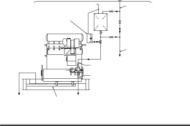
Fig. 4.03.02: Necessary capacities for PTO/RCF, BW III/RCF system
|
Deck |
|
Filling pipe |
The dimensions |
|
of dosage tank |
|
depend on actual |
Engine |
type of gear |
|
|
oil |
Main |
|
engine |
DR |
|
DS |
S |
S |
C/D |
C/D |
From purifier |
To purifier |
|
Lube oil |
||
|
||
bottom tank |
|
Fig. 4.03.03: Lubricating oil system for RCF gear
To main engine
The letters refer to the ‘List of flanges’, which will be extended by the engine builder,
when PTO systems are built on the main engine
178 25 23 5.0
MAN B&W K108ME-C6, K98MC/MC-C/ME/ME-C6/7, S90MC-C/ME-C7/8, K90ME/ME-C9, K90MC-C/ME-C6, S80MC6, S80MC-C7/8, S80ME-C7/8/9, K80ME-C9, K80MC-C/ME-C6, S70MC C/ME-C/ME-GI7/8, S70MC6, L70MC C/ME-C7/8, S65ME-C/ME-GI8, S60MC6, S60MC-C/ME-C/ME-GI7/8, L60MC-C/ME-C7/8, S50MC-C7/8, S50MC6, S50ME-B8/9
MAN Diesel |
198 43 15 6.2 |
|