Добавил:
Upload Опубликованный материал нарушает ваши авторские права? Сообщите нам.
Вуз: Предмет: Файл:

s90mec7

.pdf
Скачиваний:
92
Добавлен:
15.02.2015
Размер:
8.14 Mб
Скачать

MAN B&W

9.02


&ROMæCYLINDERæOILæSERVICE


4OæVENTINGæOFæCYLINDERæ

TANK STORAGEæTANK


OILæSERVICEæTANK

&LANGE æ


&LANGE æ

X æ0#$æ

X æ0#$æ


%. &


%. &


X


FORæMOUNTING


#OUPLINGæBOXæFOR

«


HEATINGæELEMENT


ANDæLEVELæSWITCH

MESHæFILTER


,EVELæSWITCH


4EMPERATURE


INDICATOR

)3


!,


4OæENGINEæ


CONNECTIONæ!#


&LANGEæ


X æ0#$æ


%. &

(EATINGæELEMENTæ æ7


3ETæPOINTæ æ #


"OX æ æL


$RAINæFROMæTRAYæ'æ


Page of 6


178 52 75 8.0

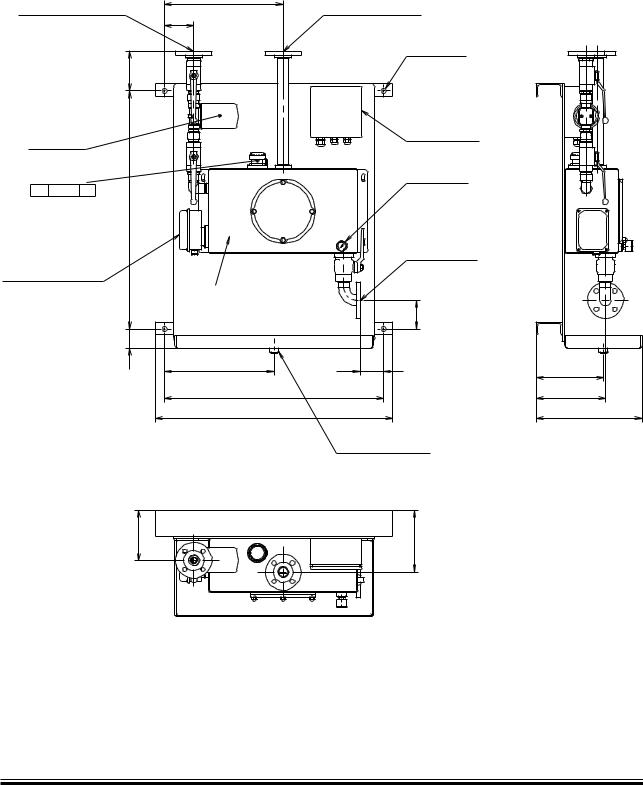
Fig. 9.02.05: Suggestion for small heating box with filter

MAN B&W ME/ME C/ME GI engines

MAN Diesel

198 55 20-9.0


MAN B&W

Piston Rod Stuffing

Box Drain Oil

10

MAN Diesel

MAN B&W

10.01


Page of 1

Stuffing Box Drain Oil System

For engines running on heavy fuel, it is important that the oil drained from the piston rod stuffing boxes is not led directly into the system oil, as the oil drained from the stuffing box is mixed with sludge from the scavenge air space.

The performance of the piston rod stuffing box on the engines has proved to be very efficient, primarily because the hardened piston rod allows a higher scraper ring pressure.

The amount of drain oil from the stuffing boxes is about 5 10 litres/24 hours per cylinder during normal service. In the running in period, it can be higher.

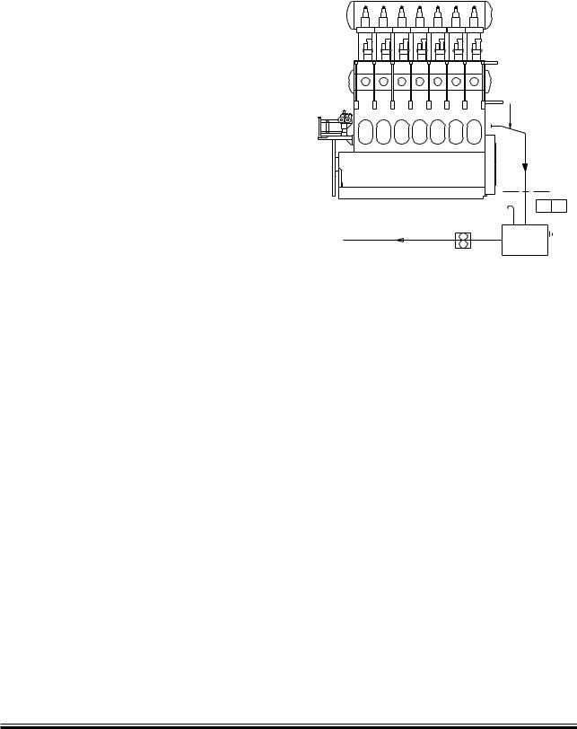
The relatively small amount of drain oil is led to the general oily waste drain tank or is burnt in the incinerator, Fig. 10.01.01.

32 mm nom. bore

AG

LS AH

Oily waste drain tank Drain

tank

198 97 44 8.1

Fig. 10.01.01: Stuffing box drain oil system

MAN B&W MC/MC C, ME/ME-B/ME C/ME GI engines

MAN Diesel

198 39 74 0.4


MAN B&W

Central Cooling

Water System

11

MAN Diesel

MAN B&W

11.01


Central Cooling Water System

The water cooling can be arranged in several configurations, the most common system choice being a Central cooling water system.

Advantages of the central cooling system:

Only one heat exchanger cooled by seawater, and thus, only one exchanger to be overhauled

All other heat exchangers are freshwater cooled and can, therefore, be made of a less expensive material

Few non corrosive pipes to be installed

Reduced maintenance of coolers and components

Increased heat utilisation.

Disadvantages of the central cooling system:

Three sets of cooling water pumps (seawater, central water and jacket water.

Higher first cost.

Page of 1

For information on the alternative Seawater Cooling System, see Chapter 12.

An arrangement common for the main engine and MAN Diesel auxiliary engines is available on request.

For further information about common cooling water system for main engines and auxiliary engines please refer to our publication:

Uni concept Auxiliary Systems for Two stroke Main

The publication is available at www.mandiesel.com under ‘Quicklinks’ → ‘Technical Papers’

MAN B&W MC/MC C, ME/ME-B/ME C/ME GI engines

MAN Diesel

198 46 96 5.3


MAN B&W

11.02


Central Cooling Water System


%XPANSIONæTANK


CENTRALæCOOLINGæWATER


04ææ


ææ!,


4HESEæVALVESæTOæBEæPROVIDED


3EAWATER


4)ææ


4%ææ


ææ)ææ!,

WITHæGRADUATEDæSCALE


OUTLET


2EGARDINGæTHEæLUBRICATINGæOILæCOOLERS


4)

THISæVALVEæSHOULDæBEæADJUSTEDæSOæTHAT


THEæINLETæTEMPERATUREæOFæTHEæCOOLING

4)


4)

,UBRICATINGæ

WATERæISæNOTæBELOWæ æª#


OILæCOOLER


!IRæPOCKETS æIFæANY æINæTHEæPIPEæLINEæ


#ENTRAL


COOLER

4)

BETWEENæTHEæPUMPS æMUSTæBEæVENTEDæ


TOæTHEæEXPANSIONæTANK


0)

4)

0)

4)

3EAWATER

#ENTRALæCOOLING

*ACKETæWATER

PUMPS

WATERæPUMPS

COOLER

0)

4)

3EAWATER INLET

3EAWATER INLET

*ACKETæCOOLINGæWATER

3EAæWATER

&UELæOIL

4HEæLETTERSæREFERæTOæLISTæOFæ@#OUNTERFLANGES æ&IG æ æ

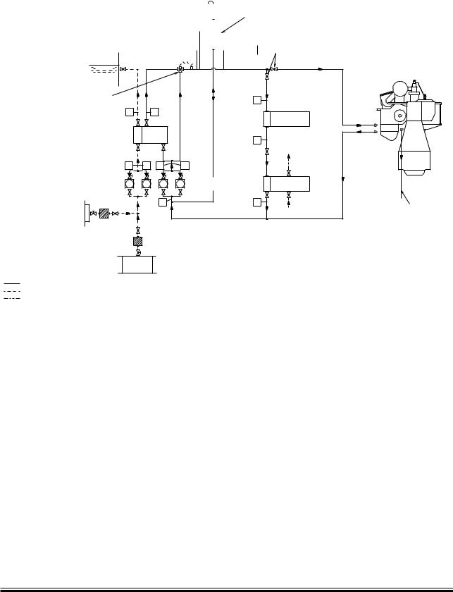
Fig. 11.02.01: Central cooling water system

Page of 1

.

!3

0

-AIN

ENGINE

#OOLINGæWATER

DRAINæAIRæCOOLER

178 52 77 1.1

The central cooling water system is characterised by having only one heat exchanger cooled by seawater, and by the other coolers, including the jacket water cooler, being cooled by central cooling water.

In order to prevent too high a scavenge air temperature, the cooling water design temperature in the central cooling water system is normally 36 °C, corresponding to a maximum seawater temperature of 32 °C.

Our recommendation of keeping the cooling water inlet temperature to the main engine scavenge

air cooler as low as possible also applies to the central cooling system. This means that the temperature control valve in the central cooling water circuit is to be set to minimum 10 °C, whereby the temperature follows the outboard seawater temperature when central cooling water temperature exceeds 10 °C.

For external pipe connections, we prescribe the following maximum water velocities:

Jacket water.................................................

3.0 m/s

Central cooling water...................................

3.0 m/s

Seawater......................................................

3.0 m/s

MAN B&W MC/MC C, ME/ME-B/ME C/ME GI engines

MAN Diesel

198 40 57 9.4


Соседние файлы в предмете [НЕСОРТИРОВАННОЕ]