

s90mec7
.pdfMAN B&W |
4.03 |
|
|
Page |
of 6 |
DMG/CFE Generators
Option: 4 85 259
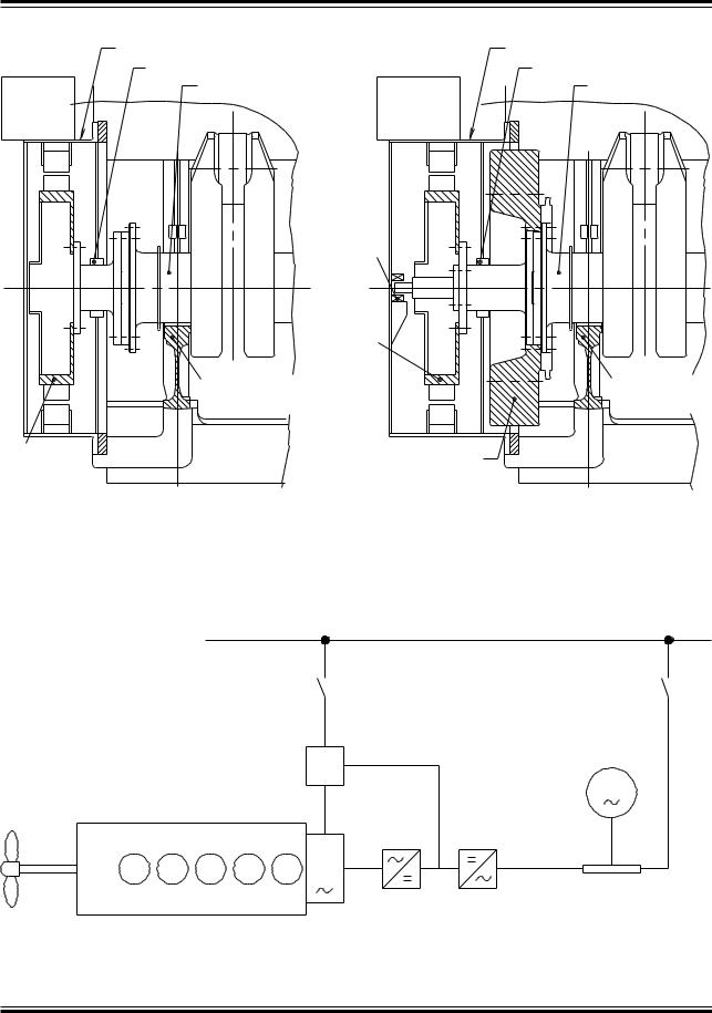
Fig. 4.01.01 alternative 5, shows the DMG/CFE (Direct Mounted Generator/Constant Frequency Electrical) which is a low speed generator with its rotor mounted directly on the crankshaft and its stator bolted on to the frame box as shown in Figs. 4.03.04 and 4.03.05.
The DMG/CFE is separated from the crankcase by a plate and a labyrinth stuffing box.
The DMG/CFE system has been developed in cooperation with the German generator manufacturers Siemens and AEG, but similar types of generator can be supplied by others, e.g. Fuji, Taiyo and Nishishiba in Japan.
For generators in the normal output range, the mass of the rotor can normally be carried by the foremost main bearing without exceeding the permissible bearing load (see Fig. 4.03.05), but this must be checked by the engine manufacturer in each case.
If the permissible load on the foremost main bearing is exceeded, e.g. because a tuning wheel
is needed, this does not preclude the use of a DMG/CFE.
Static frequency converter system |
|
|
|
Cubicles: |
|
|
Distributor |
|
Synchronous |
|
To switchboard |
condenser |
Converter |
|
|
|
|
|
Excitation |
|
|
Control |
|
Cooler
Oil seal cover
Support bearing
Rotor
Stator housing
178 06 73 3.1
Fig. 4.03.04: Standard engine, with direct mounted generator (DMG/CFE)
MAN B&W K108ME-C6, K98MC/MC-C/ME/ME-C6/7, S90MC-C/ME-C7/8, K90ME/ME-C9, K90MC-C/ME-C6, S80MC6, S80MC-C7/8, S80ME-C7/8/9, K80ME-C9, K80MC-C/ME-C6, S70MC C/ME-C/ME-GI7/8, S70MC6, L70MC C/ME-C7/8, S65ME-C/ME-GI8, S60MC6, S60MC-C/ME-C/ME-GI7/8, L60MC-C/ME-C7/8, S50MC-C7/8, S50MC6, S50ME-B8/9
MAN Diesel |
198 43 15 6.2 |
|
MAN B&W |
4.03 |
|
Page of 6 |
Stator shell |
Stator shell |
Stuffing box |
Stuffing box |
Crankshaft |
Crankshaft |
Air cooler |
Air cooler |
Support bearing
|
|
Pole wheel |
|
Main bearing No. |
Main bearing No. |
|
|
|
Pole wheel |
|
Tuning wheel |
|
|
|
Standard engine, with direct |
|
Standard engine, with direct mounted |
mounted generator (DMG/CFE) |
|
generator and tuning wheel |
|
|
178 06 63 7.1 |
Fig. 4.03.05: Standard engine, with direct mounted generator and tuning wheel
Mains, constant frequency
Synchronous
condenser
Excitation converter
G
DMG
Smoothing reactor
Diesel engine |
Static converter |
|
178 56 55 3.1
Fig. 4.03.06: Diagram of DMG/CFE with static converter
MAN B&W K108ME-C6, K98MC/MC-C/ME/ME-C6/7, S90MC-C/ME-C7/8, K90ME/ME-C9, K90MC-C/ME-C6, S80MC6, S80MC-C7/8, S80ME-C7/8/9, K80ME-C9, K80MC-C/ME-C6, S70MC C/ME-C/ME-GI7/8, S70MC6, L70MC C/ME-C7/8, S65ME-C/ME-GI8, S60MC6, S60MC-C/ME-C/ME-GI7/8, L60MC-C/ME-C7/8, S50MC-C7/8, S50MC6, S50ME-B8/9
MAN Diesel |
198 43 15 6.2 |
|

MAN B&W |
4.03 |
|
|
In such a case, the problem is solved by installing a small, elastically supported bearing in front of the stator housing, as shown in Fig. 4.03.05.
As the DMG type is directly connected to the crankshaft, it has a very low rotational speed and, consequently, the electric output current has a low frequency – normally of the order of 15 Hz.
Therefore, it is necessary to use a static frequency converter between the DMG and the main switchboard. The DMG/CFE is, as standard, laid out for operation with full output between 100% and 70% and with reduced output between 70% and 50% of the engine speed at specified MCR.
Static converter
The static frequency converter system (see Fig. 4.03.06) consists of a static part, i.e. thyristors and control equipment, and a rotary electric machine.
The DMG produces a three phase alternating current with a low frequency, which varies in accordance with the main engine speed. This alternating current is rectified and led to a thyristor inverter producing a three phase alternating current with constant frequency.
Since the frequency converter system uses a DC intermediate link, no reactive power can be supplied to the electric mains. To supply this reactive power, a synchronous condenser is used. The synchronous condenser consists of an ordinary synchronous generator coupled to the electric mains.
Extent of delivery for DMG/CFE units
The delivery extent is a generator fully built on to the main engine including the synchronous condenser unit and the static converter cubicles which are to be installed in the engine room.
The DMG/CFE can, with a small modification, be operated both as a generator and as a motor (PTI).
Page of 6
Yard deliveries are:
1.Installation, i.e. seating in the ship for the synchronous condenser unit and for the static converter cubicles
2.Cooling water pipes to the generator if water cooling is applied
3.Cabling.
The necessary preparations to be made on the engine are specified in Figs. 4.03.01a and 4.03.01b.
SMG/CFE Generators
The PTO SMG/CFE (see Fig. 4.01.01 alternative 6) has the same working principle as the PTO DMG/ CFE, but instead of being located on the front end of the engine, the alternator is installed aft of the engine, with the rotor integrated on the intermediate shaft.
In addition to the yard deliveries mentioned for the PTO DMG/CFE, the shipyard must also provide the foundation for the stator housing in the case of the PTO SMG/CFE.
The engine needs no preparation for the installation of this PTO system.
MAN B&W K108ME-C6, K98MC/MC-C/ME/ME-C6/7, S90MC-C/ME-C7/8, K90ME/ME-C9, K90MC-C/ME-C6, S80MC6, S80MC-C7/8, S80ME-C7/8/9, K80ME-C9, K80MC-C/ME-C6, S70MC C/ME-C/ME-GI7/8, S70MC6, L70MC C/ME-C7/8, S65ME-C/ME-GI8, S60MC6, S60MC-C/ME-C/ME-GI7/8, L60MC-C/ME-C7/8, S50MC-C7/8, S50MC6, S50ME-B8/9
MAN Diesel |
198 43 15 6.2 |
|

MAN B&W |
4.04 |
|
|
|
Page of 1 |
PTO/BW GCR
This section is not applicable
MAN Diesel |
198 47 58-9.0 |
|

MAN B&W |
4.05 |
|
|
|
Page of 8 |
Waste Heat Recovery Systems (WHR)
Due to the increasing fuel prices seen from 2004 and onwards many shipowners have shown interest in efficiency improvements of the power systems on board their ships. A modern two-stroke diesel engine has one of the highest thermal efficiencies of today’s power systems, but even this high efficiency can be improved by combining the diesel engine with other power systems.
One of the possibilities for improving the efficiency is to install one or more systems utilising some of the energy in the exhaust gas after the twostroke engine, which in MAN Diesel terms is designated as WHR (Waste Heat Recovery Systems).
WHR can be divided into different types of subsystems, depending on how the system utilises the exhaust gas energy. Choosing the right system for a specific project depends on the electricity demand on board the ship and the acceptable first cost for the complete installation. MAN Diesel uses the following designations for the current systems on the market:
•PTG (Power Turbine Generator):
An exhaust gas driven turbine connected to a generator via a gearbox.
•STG (Steam Turbine Generator):
A steam driven turbine connected to a generator via a gearbox. The steam is produced in a large exhaust gas driven boiler installed on the main engine exhaust gas piping system.
•Combined Turbines:
A combination of the two first systems. The arrangement is often that the power turbine is connected to the steam turbine via a gearbox and the steam turbine is further connected to a large generator, which absorbs the power from both turbines.
The PTG system will produce power equivalent to approx. 4% of the main engine SMCR, when the engine is running at SMCR. For the STG system this value is between 5 and 7% depending on the system installed. When combining the two systems, a power output equivalent to 10% of the main engine’s SMCR is possible, when the engine is running at SMCR.
As the electrical power produced by the system needs to be used on board the ship, specifying the correct size system for a specific project must be considered carefully. In cases where the electrical power consumption on board the ship is low, a smaller system than possible for the engine type may be considered. Another possibility is to install a shaft generator/motor to absorb excess power produced by the WHR. The main engine will then be unloaded, or it will be possible to increase the speed of the ship, without penalising the fuelbill.
Because the energy from WHR is taken from the exhaust gas of the main engine, this power produced can be considered as ”free”. In reality, the main engine SFOC will increase slightly, but the gain in electricity production on board the ship will far surpass this increase in SFOC. As an example, the SFOC of the combined output of both the engine and the system with power and steam turbine can be calculated to be as low as 155 g/kWh (ref. LCV 42,700 kJ/kg).
MAN B&W S90MC-C/ME-C7/8, K90ME9, K90MC-C/ME-C6
MAN Diesel |
198 57 98-9.2 |
|
MAN B&W |
4.05 |
|
|
Page |
of 8 |
Power Turbine Generator (PTG)
The power turbines of today are based on the different turbocharger suppliers’ newest designs of high-efficiency turbochargers, i.e. MAN Diesel’s TCA, ABB’s TPL and Mitsubishi’s MA turbochargers.
The power turbine basically is the turbine side of
anormal high-efficient turbocharger with some modifications to the bearings and the turbine shaft. This is in order to be able to connect it to
agearbox instead of the normal connection to the compressor side. The power turbine will be installed on a separate exhaust gas pipe from the exhaust gas receiver, which bypasses the turbochargers.
The performance of the PTG and the main engine will depend on a careful matching of the engine turbochargers and the power turbine, for which reason the turbocharger/s and the power turbine need to be from the same manufacturer. In Fig. 4.05.01, a simple diagram of the PTG arrangement is shown. The quick-opening and quick-closing valves are used in the event of a blackout of the grid, in which case the exhaust gas will bypass the power turbine.
The newest generation of high-efficiency turbochargers allows bypassing of some of the main engine exhaust gas, thereby creating a new balance of the air flow through the engine. In this way, it is possible to extract power from the power turbine equivalent to 4% of the main engine’s SMCR, when the engine is running at SMCR.
0IPE |
|
-AIN |
%LECTRICALæWIRING |
4OæFUNNEL |
SWITCHBOARD |
|
||
|
'EN 3ET |
|
|
|

 'EN 3ET
|
1UICK |
|
|
CLOSING |
|
|
VALVE |
|
|
|
0OWER |
|
1UICK |
TURBINE |
|
|
|
|
OPENING |
|
|
VALVE |
'EARBOX |
|
|
|
%XHAUSTæGASæRECEIVER |
|
|
"UTTERFLY |
1UICK |
|
VALVE |
|
|
CLOSING |
|
|
|
VALVE |
|
-AINæENGINE
3HAFT
GENERATOR
MOTOR
178 57 09-8.0
Fig. 4.05.01: PTG diagram
MAN B&W S90MC-C/ME-C7/8, K90ME9, K90MC-C/ME-C6
MAN Diesel |
198 57 98-9.2 |
|
MAN B&W |
4.05 |
|
|
Page of 8
æçæ æM |
-AINTENANCEæSPACE |
æçæ æM |
|
2EDUCTIONæGEAR |
|
0OWERæTURBINE |
'ENERATOR |
|
æM |
|
7IDTH æ æçæ æM |
|
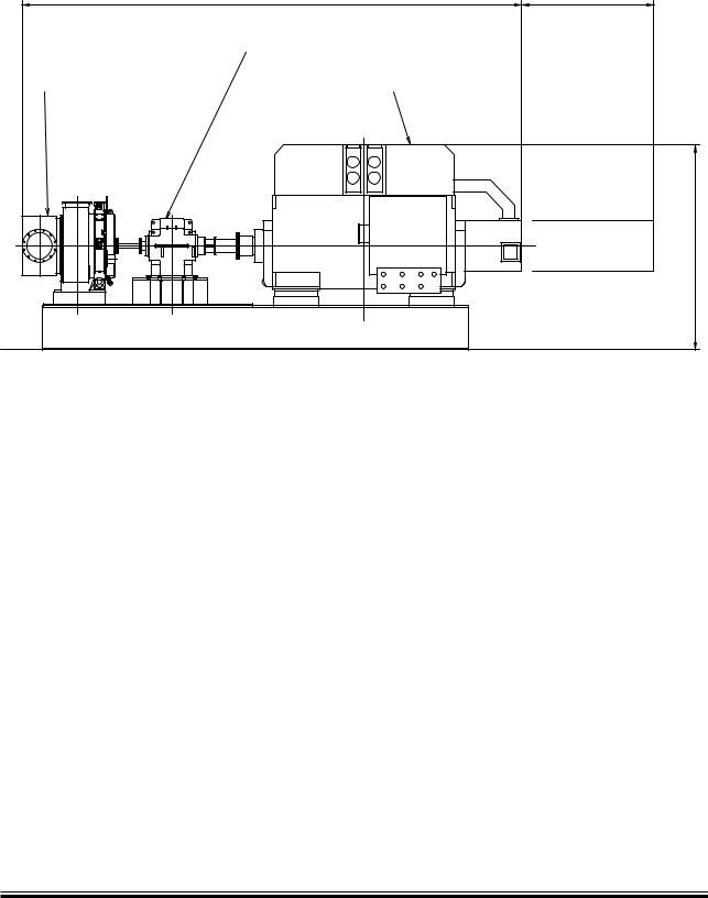
178 56 93-9.0 |
Fig. 4.05.02: The size of a 2,000 kW PTG system depending on the supplier
MAN B&W S90MC-C/ME-C7/8, K90ME9, K90MC-C/ME-C6
MAN Diesel |
198 57 98-9.2 |
|

MAN B&W |
4.05 |
|
|
Page |
of 8 |
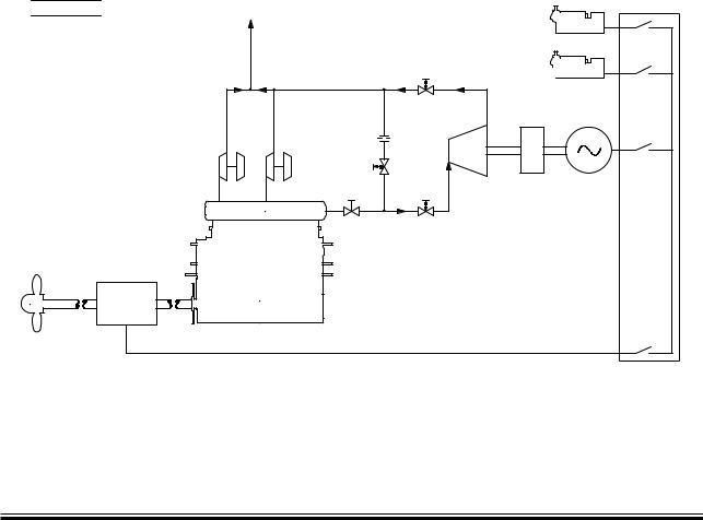
Steam Turbine Generator (STG)
In most cases the exhaust gas pipe system of the main engine is equipped with a boiler system. With this boiler, some of the energy in the exhaust gas is utilised to produce steam for use on board the ship.
If the engine is WHR matched, the exhaust gas temperature will be between 50°C and 65°C higher than on a conventional engine, which makes it possible to install a larger boiler system and, thereby, produce more steam. In short, MAN Diesel designates this system STG. Fig. 4.05.03 shows an example of the arrangement of STG.
For WHR matching the engine, a bypass is installed to increase the temperature of the exhaust gas and improve the boiler output.
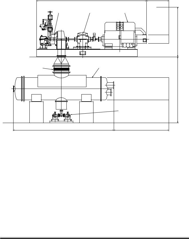
The extra steam produced in the boiler can be utilised in a steam turbine, which can be used to drive a generator for power production on board the ship. An STG system could be arranged as shown in Fig. 4.05.04, where a typical system size is shown with the outline dimensions.
The steam turbine can either be a single or dual pressure turbine, depending on the size of the system. Steam pressure for a single pressure system is 7 to 10 bara, and for the dual pressure system the high-pressure cycle will be 9 to 10 bara and the low-pressure cycle will be 4 to 5 bara.
|
4OæFUNNEL |
|
|
0IPE |
|
|
|
%LECTRICALæWIRING |
|
|
-AINæSWITCHBOARD |
3TEAM |
,0æSTEAM |
|
|
|
|
||
|
|
|
|
|
%CONOMISER |
|
'EN 3ET |
|
(0æSTEAM |
|
'EN 3ET |
|
|
|
'EN 3ET |
|
3TEAMæ |
|
|
|
REGULATINGæ |
|
|
|
VALVE |
3TEAMæ |
|
|
|
TURBINE |
|
|
"UTTERFLY |
|
|
|
6ALVE |
|
'EARBOX |
|
%XHAUSTæGASæRECEIVER |
|
|
|
4OæECONOMISER |
#ONDENSER |
#OOLING |
|
|
|
7ATER |
|
-AINæENGINE |
|
|
3HAFT |
&EEDWATERæ |
|
|
'ENERATOR |
(OTWELL |
|
|
-OTOR |
PUMP |
|
178 56 96-4.0
Fig. 4.05.03: Steam diagram
MAN B&W S90MC-C/ME-C7/8, K90ME9, K90MC-C/ME-C6
MAN Diesel |
198 57 98-9.2 |
|
MAN B&W |
4.05 |
|
|
Page of 8
|
|
-AINTENANCEæSPACE |
|
æçæ æM |
æ æçæ æM |
3TEAMæTURBINE |
2EDUCTIONæGEAR |
'ENERATOR |
|
|
/VERHAULæHEIGHT æMæçæ |
%XPANSIONæJOINT |
#ONDENSER |
|
|
|
æMæçæ |
|
|
#ONDENSATEæPUMP |
|
|
-AINTENANCEæSPACE |
APPROX æ æçæ æM |
|
æçæ M |
|
7IDTH æ æçæ æM |
|
|
|
178 57 00-1.0 |
Fig. 4.05.04: Typical system size for 3.000 kW STG system
MAN B&W S90MC-C/ME-C7/8, K90ME9, K90MC-C/ME-C6
MAN Diesel |
198 57 98-9.2 |
|
MAN B&W |
4.05 |
|
|
Page |
of 8 |
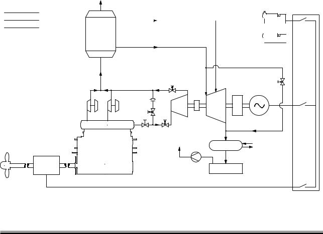
Combined Turbines
Because the installation of the power turbine also will result in an increase of the exhaust gas temperature after the turbochargers, it is possible to install both the power turbine, the larger boiler and steam turbine on the same engine. This way, the energy from the exhaust gas is utilised in the best way possible by today’s components.
When looking at the system with both power and steam turbine, quite often the power turbine and the steam turbine are connected to the same generator. In some cases, it is also possible to have each turbine on a separate generator. This is, however, mostly seen on stationary engines, where the frequency control is simpler because of the large grid to which the generator is coupled.
For marine installations the power turbine is, in most cases, connected to the steam turbine via a gearbox, and the steam turbine is then connected to the generator. It is also possible to have a generator with connections in both ends, and then connect the power turbine in one end and the steam turbine in the other. In both cases control of one generator only is needed.
For dimensions of a typical system see Fig. 4.05.06.
As mentioned, the systems with steam turbines require a larger boiler to be installed. The size of the boiler system will be roughly three to four times the size of an ordinary boiler system, but the actual boiler size has to be calculated from case to case.
0IPE
%LECTRICALæWIRING
3TEAM
3HAFT
GENERATOR
MOTOR
4OæFUNNEL
-AINæSWITCHBOARD


 'EN 3ET ,0æSTEAM

%CONOMISER 


 'EN 3ET

(0æSTEAM
|
3TEAMæ |
1UICKæCLOSINGæVALVE |
REGULATINGæ |
|
VALVE |
1UICK |
0OWERæ |
|
TURBINE 'EARBOX |
||
/PENING |
||
6ALVE |
|
|
%XHAUSTæGASæRECEIVER |
1UICKæ |
|
"UTTERFLYæ |
||
VALVE |
CLOSINGæ |
|
|
VALVE |
|
|
4OæECONOMISER |
|
-AINæENGINE |
|
|
|
&EEDWATERæ |
|
|
PUMP |
3TEAMæ |
|
|
TURBINE |
|
|
'EARBOX |
|
|
#ONDENSER |
#OOLINGæ |
|
WATER |
||
|
||
(OTWELL |
|
178 57 03-7.0
Fig. 4.05.05: Combined turbines diagram
MAN B&W S90MC-C/ME-C7/8, K90ME9, K90MC-C/ME-C6
MAN Diesel |
198 57 98-9.2 |
|