
s90mec7
.pdf
MAN B&W |
5.11 |
|
|
|
Page of 1 |
Engine Seating and Holding Down Bolts
Please note that the latest version of most of the drawings of this section is available for download at www.mandiesel.com under ‘Marine’ → ‘Low Speed’ → ‘Installation Drawings’. First choose engine series, then engine type and select ‘Engine seating’ in the general section of the list of drawings available for download.
Engine Seating and Arrangement of
Holding Down Bolts
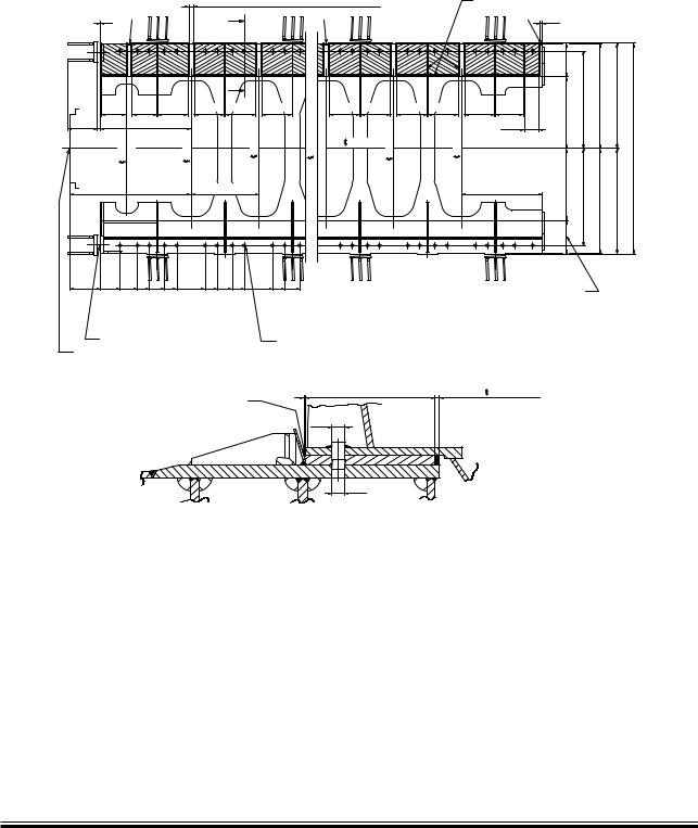
The dimensions of the seating stated in Figs. 5.12.01 and 5.12.02 are for guidance only.
The engine is designed for mounting on epoxy chocks, EoD 4 82 102, in which case the underside of the bedplate’s lower flanges has no taper.
The epoxy types approved by MAN Diesel are:
•‘Chockfast Orange PR 610 TCF’ from ITW Philadelphia Resins Corporation, USA
•‘Durasin’ from Daemmstoff Industrie Korea Ltd
•‘Epocast 36’ from
H.A. Springer - Kiel, Germany.
MAN B&W MC/MC C, ME/ME-C/ME GI/ME B engines
MAN Diesel |
198 41 76 5.6 |
|
MAN B&W |
5.12 |
|
|
Page of 3
Epoxy Chocks Arrangement
|
|
|
|
!LLæHOTæWORKæONæTHEæTANKTOPæMUSTæBEæFINISHEDæBEFOREæTHEæEPOXYæISæCAST |
|
|
|
|
|
|
|
|
|
|||||||
|
|
|
|
)FæMEASURINGæPINSæAREæREQUIRED æWEæRECOMMENDæTHATæTHEYæAREæINSTALLED |
|
|
|
|
|
|
|
|
|
|||||||
|
|
|
|
ATæTHEæPOSITIONSæMARKEDæBYæ |
|
|
|
|
|
|
|
|
|
|
|
|
|
|
||
|
|
|
|
|
æMMæFREEæSPACESæFORæSUPPORTINGæWEDGES |
|
|
|
|
æMMæTHICKæDAMMINGS |
|
|
|
|||||||
|
|
|
|
|
|
|
|
|
|
|
|
|
|
|
|
|||||
|
|
|
|
|
|
! |
|
|
|
|
|
|
|
|
|
|
|
|
|
|
|
|
|
|
|
|
|
|
|
|
|
|
|
|
|
|
|
|
|||
|
|
|
|
|
|
|
|
|
|
|
|
|
|
|
|
|
|
|
|
|
|
|
|
|
|
|
! |
|
|
|
|
|
|
|
|
|
|
|
¢ |
|
|
|
|
|
|
|
|
|
|
|
|
|
|
|
|
|
|
|
|
|||
|
|
|
|
æææ!FTæCYL |
|
æææCYL |
|
æææCYL |
|
|
æææCYL |
|
|
æææCYL |
|
|
|
|
|
|
|
|
æææ4HRUST æBEARING |
|
|
æææ%NGINE |
|
|
|
|
|
|
|
||||||||
|
|
|
|
|
|
|
|
|
|
|
|
|
|
|
|
|
|
|
||
|
|
|
|
|
|
|
|
|
|
|
|
|
|
|
|
|
¢ |
|
|
|
|
|
|
|
|
|
|
|
|
|
|
|
|
|
|
|
|
||||
|
|
|
|
|
|
|
|
|
|
|
|
|
|
|
|
|
|
|
|
|
|
|
æ ¢ |
æ ¢ ¢ |
|
|
|
|
|
|
|
|
|
|
|
4HEæWIDTHæOFæMACHININGæON |
|
|
|||
æ |
æ |
¢ ¢ |
¢ ¢ |
¢ ¢ |
¢ ¢ |
¢ |
|
|
|
|
|
|
THEæUNDERSIDEæOFæBEDPLATE |
|
|
|||||
|
|
|
|
|
|
|
|
|
|
|
|
|||||||||
|
X æOFFæ æHOLES |
|
|
æHOLESæINæTHEæBEDPLATEæANDæ æHOLESæINæTHEæTOPæPLATE |
|
|
|
|
|
|
||||||||||
%NDæFLANGEæOFæTHRUSTæSHAFT |
|
|
|
|
|
|
|
|
|
|
|
|
|
|
|
|
||||
|
|
|
|
|
|
|
|
|
|
!ç! |
|
|
|
|
|
|
|
|
|
|
|
|
|
|
%POXYæWEDGESæTOæBE |
|
|
%FFECTIVEæ |
|
|
|
æTOææææENGINE |
|
|
|
|
|
||||
|
|
|
|
|
|
|
|
|
|
|
|
|
|
|
|
|
|
|||
|
|
|
|
CHISELLEDæAFTER |
|
|
|
|
|
|
|
|
|
|
|
|
|
|
|
|
|
|
|
|
CURINGæTOæENABLE |
|
|
|
|
|
|
|
|
|
|
|
|
|
|
||
|
|
|
|
MOUNTINGæOFæSIDE |
|
|
|
|
|
|
|
|
|
|
|
|
|
|
||
|
|
|
|
CHOCKæLINERS |
|
|
|
|
|
|
|
|
|
|
|
|
|
|
|
|
|
|
|
|
|
|
|
|
|
|
|
|
|
|
|
|
|
|
|
|
|
For details of chocks and bolts see special drawings.
For securing of supporting chocks see special drawing.
This drawing may, subject to the written consent of the actual engine builder concerned, be used as a basis for marking off and drilling the holes for holding down bolts in the top plates, provided that:
178 19 89-1.2
1)The engine builder drills the holes for holding down bolts in the bedplate while observing the toleranced locations indicated on MAN B&W drawings for machining the bedplate
2)The shipyard drills the holes for holding down bolts in the top plates while observing the toleranced locations given on the present drawing
3)The holding down bolts are made in accordance with MAN B&W drawings of these bolts.
Fig. 5.12.01: Arrangement of epoxy chocks and holding down bolts
MAN B&W S90MC-C/ME-C
MAN Diesel |
198 41 79-0.2 |
|
MAN B&W |
5.12 |
|
|
Page of 3
Engine Seating Profile
|
|
|
Section A-A |
|
|
|
|
|
||
4HISæSPACEæTOæBEæKEPTæFREEæFROMæPIPESæETC æALONGæBOTHæSIDES |
|
|
|
|
|
|
||||
OFæTHEæENGINEæINæORDERæTOæFACILITATEæTHEæOVERHAULæWORKæON |
|
|
|
|
|
|
||||
HOLDINGæDOWNæBOLTS æSUPPORTINGæCHOCKSæANDæSIDEæCHOCKS |
|
|
|
|
|
#ENTRELINE |
||||
|
|
|
|
|
|
|
|
|
|
|
|
|
|
|
|
|
|
|
|
|
CRANKSHAF |
|
|
|
|
|
|
|
|
|
|
|
|
|
|
|
|
|
|
|
|
|
|
|
|
|
|
|
|
|
|
|
|
|
|
|
|
|
|
|
|
|
|
|
#ENTRELINEæENGINE |
|
|
|
|
|
|
|
|
|
||
|
|
|
|
|
|
|
|
|
||
$ |
|
|
|
|
|
|
|
|
|
|
" |
|
|
|
|
|
æææ æç |
|
|
|
|
|
|
|
|
|
|
|
|
|
|
|
|
|
|
|
|
|
)FæREQUIREDæBYæCLASSIFICATION |
|
|
|
|
|
|
|
|
SOCIETY æAPPLYæTHISæBRACKET |
|
|
|
|
||
|
|
|
|
|
4HICKNESSæOFæBRACKETæISæTHE |
|
|
|
|
|
|
|
|
|
SAMEæASæTHICKNESSæOFæ |
|
|
||||
|
|
|
|
|
|
|||||
|
|
|
|
FLOORPLATES |
|
|||||
|
|
|
|
|
|
|||||
|
|
|
|
|
|
|
||||
|
" |
|
|
|
|
|
|
|
|
|
|
|
2 |
|
|
|
|
|
|
||
|
|
|
|
|
|
|
|
|
||
|
|
|
|
|
|
|
|
|
|
|
|
|
|
|
|
2 |
|
|
|
|
|
|
|
|
|
|
|
|
|
|
|
|
|
|
|
|
|
|
|
|
|
||
|
|
|
|
|
|
|
|
|
|
|
|
|
|
|
|
|
|
|
|
|
|
|
|
|
|
|
|
|
|
|
|
|
|
|
|
|
|
|
|
|
|
|
|
|
|
|
|
|
|
|
|
|
|
|
4HICKNESSæOFæFLOORPLATESæBETWEENæMAIN |
3LOTSæTOæBEæCUTæINæVERTICAL |
|
|
|
|
|
|
|||
ENGINEæGIRDERSæ æMM |
|
FLOORPLATESæTOæCLEARæNUTS |
|
|
|
|
|
|
||
|
|
WHENæNECESSARY |
|
|
|
|
|
|
|
|
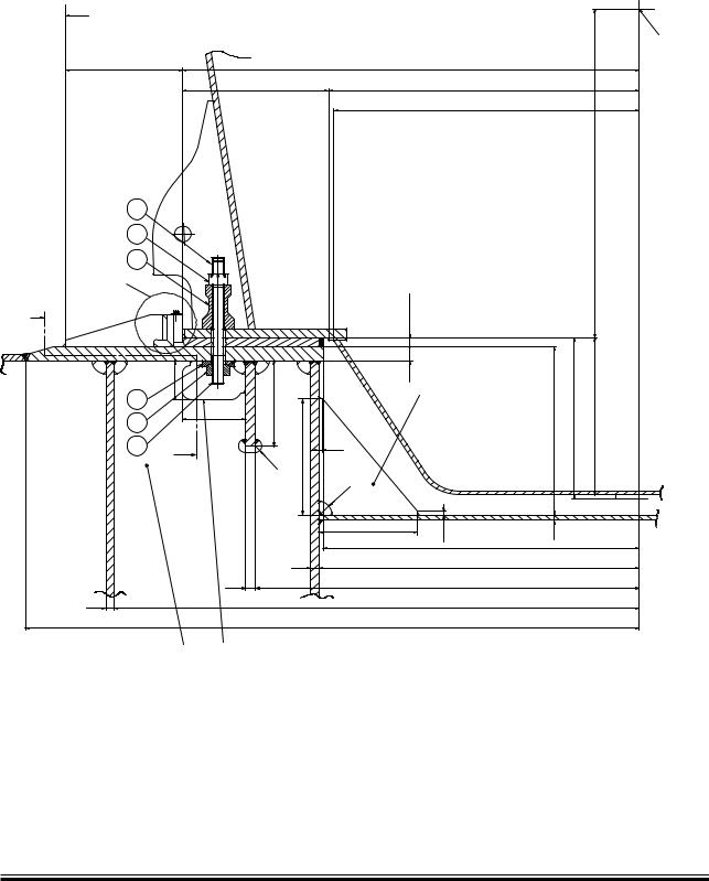
Holding down bolts, option: 4 82 602 include:
1.Protecting cap
2.Spherical nut
3.Spherical washer
4.Distance pipe
5. Round nut |
178 19 85-4.3 |
6.Holding down bolt
Fig.5.12.02a: Profile of engine seating with vertical oil outlet
MAN B&W S90MC-C/ME-C
MAN Diesel |
198 41 93-2.3 |
|
MAN B&W |
5.12 |
|
|
3ECTION¬" " |
#ENTREæOFæ |
MAINæBEARING |
! |
! |
Page of 3
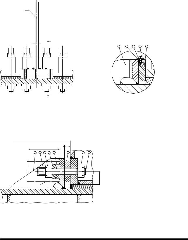
Side chock brackets, option: 4 82 622 includes: 1. Side chock brackets
Side chock liners, option: 4 82 620 includes:
2.Liner for side chock
3.Lock plate
4.Washer
5.Hexagon socket set screw
$ETAIL¬$
178 57 34-8.0
Fig. 5.12.02b: Profile of engine seating, end chocks, option: 4 82 620
|
|
|
|
|
|
|
|
|
|
|
|
4APERæ æ |
|
|
|
|
|
|
|
|
|
|
|
|
|
|
|
|
|
|
|
ABOUTæ |
|
|
|
|
|
|
|
|
|
|
|
|
|
|
|
3PACEæFORæHYDRAULIC |
|
|
|
|
|
|
|
TIGHTENINGæJACK |
|
|
|
|
|
|
|
End chock bolts, option: 4 82 610 includes:
1.Stud for end chock bolt
2.Round nut
3.Round nut
4.Spherical washer
5.Spherical washer
6.Protecting cap
End chock liner, option: 4 82 612 includes: 7. Liner for end chock
End chock brackets, option: 4 82 614 includes: 8. End chock bracket
178 57 30-0.0
Fig. 5.12.02c: Profile of engine seating, end chocks, option: 4 82 610
MAN B&W S90MC-C/ME-C
MAN Diesel |
198 41 93-2.3 |
|

MAN B&W |
5.13 |
|
|
Engine Top Bracing
The so-called guide force moments are caused by the transverse reaction forces acting on the crossheads due to the connecting rod and crankshaft mechanism. When the piston of a cylinder is not exactly in its top or bottom position the gas force from the combustion, transferred through the connecting rod, will have a component acting on the crosshead and the crankshaft perpendicularly to the axis of the cylinder. Its resultant is acting on the guide shoe and together they form a guide force moment.
The moments may excite engine vibrations moving the engine top athwart ships and causing a rocking (excited by H-moment) or twisting (excited by X-moment) movement of the engine. For engines with less than seven cylinders, this guide force moment tends to rock the engine in the transverse direction, and for engines with seven cylinders or more, it tends to twist the engine.
The guide force moments are harmless to the engine except when resonance vibrations occur in the engine/double bottom system. They may, however, cause annoying vibrations in the superstructure and/or engine room, if proper countermeasures are not taken.
As a detailed calculation of this system is normally not available, MAN Diesel recommends that top bracing is installed between the engine’s upper platform brackets and the casing side.
However, the top bracing is not needed in all cases. In some cases the vibration level is lower if the top bracing is not installed. This has normally to be checked by measurements, i.e. with and without top bracing.
If a vibration measurement in the first vessel of a series shows that the vibration level is acceptable without the top bracing, we have no objection to the top bracing being removed and the rest of the series produced without top bracing. It is our experience that especially the 7-cylinder engine will often have a lower vibration level without top bracing.
Page of 2
Without top bracing, the natural frequency of the vibrating system comprising engine, ship’s bottom, and ship’s side is often so low that resonance with the excitation source (the guide force moment) can occur close to the normal speed range, resulting in the risk of vibration.
With top bracing, such a resonance will occur above the normal speed range, as the natural frequencies of the double bottom/main engine system will increase. The impact of vibration is thus lowered.
The top bracing is normally installed on the exhaust side of the engine, but can alternatively be installed on the manoeuvring side. A combination of exhaust side and manoeuvring side installation is also possible.
The top bracing system is installed either as a mechanical top bracing or a hydraulic top bracing. Both systems are described below.
Mechanical top bracing
The mechanical top bracing comprises stiff connections between the engine and the hull.
The top bracing stiffener consists of a double bar tightened with friction shims at each end of the mounting positions. The friction shims allow the top bracing stiffener to move in case of displacements caused by thermal expansion of the engine or different loading conditions of the vessel. Furthermore, the tightening is made with a
well-defined force on the friction shims, using disc springs, to prevent overloading of the system in case of an excessive vibration level.
MAN B&W MC/MC C, ME/ME-B/ME C/ME GI engines
MAN Diesel |
198 46 72 5.7 |
|
MAN B&W |
5.13 |
|
|
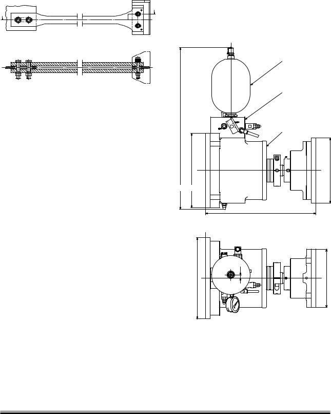
The mechanical top bracing is to be made by the shipyard in accordance with MAN Diesel instructions.
!
! |
!!
178 23 61-6.1
Fig. 5.13.01: Mechanical top bracing stiffener. Option: 4 83 112
Hydraulic top bracing
The hydraulic top bracing is an alternative to the mechanical top bracing used mainly on engines with a cylinder bore of 50 or more. The installation normally features two, four or six independently working top bracing units.
The top bracing unit consists of a single-acting hydraulic cylinder with a hydraulic control unit and an accumulator mounted directly on the cylinder unit.
The top bracing is controlled by an automatic switch in a control panel, which activates the top bracing when the engine is running. It is possible to programme the switch to choose a certain rpm range, at which the top bracing is active. For service purposes, manual control from the control panel is also possible.
When active, the hydraulic cylinder provides a pressure on the engine in proportion to the vibration level. When the distance between the hull and engine increases, oil flows into the cylinder under pressure from the accumulator. When the distance decreases, a non-return valve prevents the oil from flowing back to the accumulator, and the pressure rises. If the pressure reaches a preset maximum value, a relief valve allows the oil to flow back to the accumulator, hereby maintaining the force on the engine below the specified value.
Page of 2
By a different pre-setting of the relief valve, the top bracing is delivered in a low-pressure version (26 bar) or a high-pressure version (40 bar).
The top bracing unit is designed to allow displacements between the hull and engine caused by thermal expansion of the engine or different loading conditions of the vessel.
|
/ILæ!CCUMULATOR |
|
(YDRAULICæ#ONTROLæ5NIT |
|
#YLINDERæ5NIT |
|
|
|
|
|
|
(ULLæSIDE |
%NGINEæSIDE |
|
|
|
|
|
178 57 48-8.0 |
Fig. 5.13.02: Outline of a hydraulic top bracing unit. The unit is installed with the oil accumulator pointing either up or down. Option: 4 83 123
MAN B&W MC/MC C, ME/ME-B/ME C/ME GI engines
MAN Diesel |
198 46 72 5.7 |
|

MAN B&W |
5.14 |
|
|
|
Page of 1 |
Mechanical Top Bracing
This section is available on request
MAN B&W K98MC6/7, K98MC-C6/7, L35MC6, S26MC6, ME/ME-B/ME C/ME GI engines
MAN Diesel |
198 47 64 8.2 |
|

MAN B&W |
5.15 |
|
|
|
Page of 1 |
Hydraulic Top Bracing Arrangement
This section is available on request
MAN Diesel |
198 48 45-20 |
|
MAN B&W |
5.16 |
|
|
Components for Engine Control System
Installation of ECS in the Engine Control Room
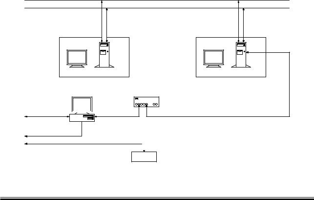
The following items are to be installed in the ECR (Engine Control Room):
•2 pcs EICU (Engine Interface Control Unit) (1 pcs only for ME-B engines)
•1 pcs MOP (Main Operating Panel) Touch display, 15”
PC unit
•1 pcs Track ball for MOP
•1 pcs PMI system
Display, 19”
PC unit
•1 pcs Back up MOP Display, 15” PC unit Keyboard
•1 pcs Printer
•1 pcs Ethernet Hub
Page of 4
The EICU functions as an interface unit to ECR related systems such as AMS (Alarm and Monitoring System), RCS (Remote Control System) and Safety System. On ME-B engines the EICU also controls the HPS.
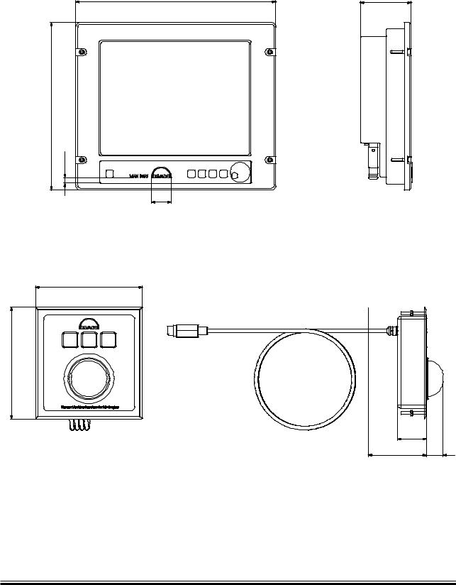
The MOP is the operator’s interface to the ECS. From there the operator can control and see status of the engine and the ECS. The MOP is a PC with a flat touch screen.
The Back up MOP consists of a PC unit with keyboard and display and serves as a back up in case the MOP should break down.
The PMI offline system is equipped with a standard PC. The PMI system serves as a pressure analyse system. See Section 18.02.
Optional items to be mounted in the ECR include the CoCoS EDS which can be purchased separately and applied on the PC for the PMI offline system. See Section 18.03.
%#3æ.ETWORKæ! |
|
%#3æ.ETWORKæ" |
|
-/0æ! |
-/0æ" |
0-) #O#O3æ0#
3HIPæ,!.æ  fæ%THERNET
3ERIALæ!-3æ
fæ%THERNETæ !-3
(5"

 fæ%THERNET
0RINTER
fæ%THERNET
fæ%THERNET æSUPPLYæWITHæ(5" æCABLEæLENGTHæ æMETERæ9ARDæ3UPPLY
178 57 50-3.0
Fig. 5.16.01 Network and PC components for the ME/ME-B Engine Control System
MAN B&W ME/ME-C/ME-GI/ME B engines
MAN Diesel |
198 46 97 7.4 |
|
MAN B&W |
5.16 |
|
|
MOP (Main Operating Panel)
|
|
Track ball
Fig. 5.16.02 MOP and track ball for the ME/ME-B Engine Control System
Page of 4
|
178 57 48-1.0
MAN B&W ME/ME-C/ME-GI/ME B engines
MAN Diesel |
198 46 97 7.4 |
|
