Добавил:
Upload Опубликованный материал нарушает ваши авторские права? Сообщите нам.
Вуз: Предмет: Файл:

s90mec7

.pdf
Скачиваний:
92
Добавлен:
15.02.2015
Размер:
8.14 Mб
Скачать

MAN B&W

6.04


Page of 12

Exhaust Gas Amount and Temperature

Influencing factors

The exhaust gas data to be expected in practice depends, primarily, on the following three factors:

a) The specified MCR point of the engine (point M):

PM

: power in kW at SMCR point

nM

: speed in r/min at SMCR point

and to a certain degree on the matching point O with the percentage power PO% = % of SMCR power:

PO% = (PO/PM) x 100%

b)The ambient conditions, and exhaust gas back pressure:

Tair

: actual ambient air temperature, in °C

pbar

: actual barometric pressure, in mbar

TCW

: actual scavenge air coolant temperature,


in °C

∆pM

: exhaust gas back pressure in mm WC at


specified MCR

c)The continuous service rating of the engine (point S), valid for fixed pitch propeller or controllable pitch propeller (constant engine speed):

PS : continuous service rating of engine, in kW

Calculation Method

To enable the project engineer to estimate the actual exhaust gas data at an arbitrary service rating, the following method of calculation may be used.

The partial calculations based on the above influencing factors have been summarised in equations [4] and [5].

Mexh

: exhaust gas amount in kg/h, to be found


Texh

: exhaust gas temperature in °C, to be found


P


∆m


∆M


∆m


P


Mexh

= ML1 x 

M

x  1 +


M%​ x    1 +


amb%​ x 1 +


s%​ x

S%

kg/h

+/ 5% [4]


PL1


100


100


100

100


Texh = TL1 + ∆TM + ∆TO + ∆Tamb + ∆TS

°C /+15 °C


[5]

where, according to ‘List of capacities’, i.e. referring to ISO ambient conditions and 300 mm WC

back pressure and specified/matched in L1:


ML1: exhaust gas amount in kg/h at nominal MCR (L1)


TL1: exhaust gas temperature after turbocharger in °C at nominal MCR (L1)


Fig. 6.04.06: Summarising equations for exhaust gas amounts and temperatures


The partial calculations based on the influencing factors are described in the following:

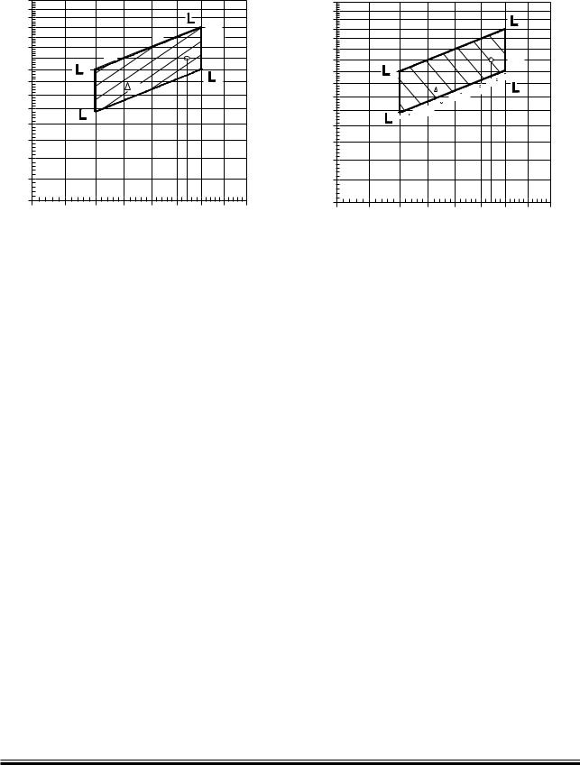
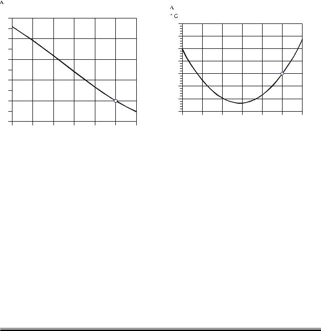
a)Correction for choice of specified MCR point

When choosing a specified MCR point ‘M’ other than the nominal MCR point ‘L1’, the resulting

changes in specific exhaust gas amount and temperature are found by using as input in diagrams the corresponding percentage values (of L1) for specified MCR power PM% and speed nM%:

PM% = PM/PL1 x 100% nM% = nM/nL1 x 100%

MAN B&W ME-B, ME/ME C, ME GI engines

MAN Diesel

198 43 18 1.2


MAN B&W Diesel A/S

6.04


Specified MCR


power, % of L1


PM%


110%


100%


1

0%


1%


-1%

90%


M

-2%


2%


-3%

80%


3


2


mM%


70%


60%


4


50%


40%


70%

75%

80%

85%

90%

95%

100% 105% 110% nM%


Specified MCR engine speed, % of L1

mM% = 14 x ln (PM/PL1) – 24 x ln (nM/nL1)


178 51 10-5.0

Page 9 of 12

Specified MCR power, % of L1

PM%


110%


100%


1


0%

90%


M


-2%


80%

3


-8 C


Tm

-10 C

70%

-12 C


2


-14 C


-16 C


-18 C


-20 C


60%

4


50%


40%

70%

75%

80% 85% 90% 95% 100% 105% 110% nM%

Specified MCR engine speed, % of L1

TM = 15 x ln (PM/PL1) + 45 x ln (nM/nL1)

178 51 14-2.0

Fig. 6.04.07: Change of specific exhaust gas amount, ∆mM% in % of L1 value and independent of PO

mM%

: change of specific exhaust gas amount,


in % of specific gas amount at nominal


MCR (L1), see Fig. 6.04.07.


TM

: change in exhaust gas temperature after


turbocharger relative to the L1 value, in °C,


see Fig. 6.04.08. (PO = PM)


TO

: extra change in exhaust gas temperature


when matching point O lower than 100% M:


PO% = (PO/PM) x 100%.


TO = - 0.3 x (100 - PO%)

[6]

Fig. 6.04.08: Change of exhaust gas temperature, ∆TM in point M, in °C after turbocharger relative to L1 value and valid for PO = PM

b)Correction for actual ambient conditions and back-pressure

For ambient conditions other than ISO 3046/1 1995 (E), and back-pressure other than 300 mm WC at specified MCR point (M), the correction factors stated in the table in Fig. 6.04.09 may be used as a guide, and the corresponding relative change in the exhaust gas data may be found from equations [7] and [8], shown in Fig. 6.04.10.

Parameter

Change

Change of

Change of


exhaust gas

exhaust gas


temperature

amount


Blower inlet temperature

+ 10° C

+ 16.0° C

- 4.1 %

Blower inlet pressure (barometric pressure)

+ 10 mbar

- 0.1° C

+ 0.3 %

Charge air coolant temperature

+ 10° C

+ 1.0° C

+ 1.9 %

(seawater temperature)


Exhaust gas back pressure at the specified MCR point

+ 100 mm WC

+ 5.0° C

-1.1 %


Fig. 6.04.09: Correction of exhaust gas data for ambient conditions and exhaust gas back pressure

S90ME-C

198 44 21-0.1

MAN B&W

6.04


Page 10 of 12


Mamb%

= 0.41 x (Tair 25) + 0.03 x (pbar 1000) + 0.19 x (TCW 25 ) 0.011 x (pM 300) %

[7]

Tamb

= 1.6 x (Tair 25) 0.01 x (pbar 1000) +0.1 x (TCW 25) + 0.05 x (pM 300) °C

[8]

where the following nomenclature is used:


Mamb%

: change in exhaust gas amount, in % of amount at ISO conditions


Tamb

: change in exhaust gas temperature, in °C compared with temperatures at ISO conditions

Fig. 6.04.10: Exhaust gas correction formula for ambient conditions and exhaust gas back pressure

mS%


%


16


14


12


10


8


6


4


2


0


M


-2


-4


50

60

70

80

90

100

110 PS%


Engine load, % specified MCR power


178 24 62 3.0

TS


20


15


10


5


0


M


-5


-10


-15


50

60

70

80

90

100

110

PS%


Engine load, % specified MCR power


178 24 63 5.0

PS% = (PS/PM) x 100%

mS%= 37 x (PS/PM)3 83 x (PS/PM)2 + 31 x (PS/PM) + 15

Fig. 6.04.11: Change of specific exhaust gas amount, ms% in % at part load, and valid for FPP and CPP

c)Correction for engine load

Figs. 6.04.11 and 6.04.12 may be used, as guidance, to determine the relative changes in the specific exhaust gas data when running at part load, compared to the values in the

specified MCR point, i.e. using as input PS% = (PS/PM) x 100%:

PS% = (PS/PM) x 100%

TS = 262 x (PS/PM)2 413 x (PS/PM) + 151

Fig. 6.04.12: Change of exhaust gas temperature, TS in °C at part load, and valid for FPP and CPP

ms% : change in specific exhaust gas amount, in % of specific amount at specified MCR point, see Fig. 6.04.11.

Ts

: change in exhaust gas temperature, in °C,


see Fig. 6.04.12.

MAN B&W MC/MC C, ME/ME-B/ME C/ME GI engines

MAN Diesel

198 43 20 3.3


MAN B&W Diesel A/S

6.04


Page 11 of 12

Calculation of Exhaust Data for Derated Engine

Example 3:

Expected exhaust data for a derated 6S90ME-C with high efficiency turbocharger and with fixed pitch propeller.

Based on the engine ratings below, and by means of an example, this chapter will show how to calculate the expected exhaust gas amount and temperature at service rating, and for a given ambient reference condition different from ISO.

The calculation is made for the service rating (S) being 80%of the specified MCR power of the diesel engine.

Nominal MCR, (L1) PL1: 29,340 kW (100.0%) and 76.0 r/min (100.0%) Specified MCR, (M) PM: 24,939 kW (85.0%) and 73.7 r/min (97.0%)

Matching point, (O) PO: 22,445 kW (76.5%) and 71.2 r/min (93.7%) PO = 90.0 of PM

Service rating, (S) PS: 19,951 kW and 68.4 r/min PS = 80.0% of PM

Reference conditions


Air temperature Tair ........................................

20° C

Scavenge air coolant temperature TCW

......... 18° C

Barometric pressure pbar .....................

1,013 mbar

Exhaust gas back-pressure


at specified MCR pM .......................

300 mm WC

a) Correction for choice of specified MCR point M and matching point O:

P

M%

= 24,939

x 100 = 85.0%


29,340


n


=

73.7

x 100 = 97.0%

M%


76.0


By means of Figs. 6.05.07 and 6.05.08:

∆mM%

= -1.54 %

∆TM

= -3.8° C

As the engine is matched in O lower than 100% M, and PO% = 90.0% of PM

we get by means of equation [6]

∆TO = - 0.3 x (100 - 90.0) = - 3.0° C

b) Correction for ambient conditions and backpressure:

By means of equations [7] and [8]:

∆Mamb% = - 0.41 x (20 - 25) + 0.03 x (1,013 - 1,000)


+ 0.19 x (18 - 25) - 0.011 x (300 - 300) %

∆Mamb% = + 1.11%

∆Tamb

= 1.6 x (20 - 25) - 0.01 x (1,013 - 1,000)


+ 0.1 x (18 - 25) + 0.05 x (300 - 300) °C

∆Tamb

= - 8.8° C

c) Correction for the engine load:

Service rating = 80% of specified MCR power By means of Figs. 6.04.11 and 6.04.12:

∆mS%

= + 5.6%

∆TS

= - 11.7 °C

S90ME-C

198 45 52-7.1

MAN B&W Diesel A/S

6.04


Final calculation

By means of equations [4] and [5], the final result is found taking the exhaust gas flow ML1 and temperature TL1 from the ‘List of Capacities’:

ML1

= 268,800 kg/h


M

exh

= 268,800 x 23,424 x (1 + -1.54

) x


29,280

100


(1 +

1.11


) x (1 + 5.6 ) x

80 = 192,157 kg/h


100


100

100


Mexh

= 192,200 kg/h +/- 5%


The exhaust gas temperature

TL1

= 245° C


Texh

= 245 - 3.8 - 3.0 - 8.8 - 11.7 = 217.7° C

Texh

= 217.7° C -/+15° C


Page 12 of 12

Exhaust gas data at specified MCR (ISO)

At specified MCR (M), the running point may be in equations [4] and [5] considered as a service point where PS% = 100, ms% = 0.0 and Ts = 0.0.

For ISO ambient reference conditions where Mamb% = 0.0 and Tamb = 0.0, the corresponding calculations will be as follows:

M

exh,M

= 268,800 x 24,939

x (1 + -1.54

) x (1 +

0.0

)


29,340

100


100


x (1 + 0.0 ) x 100.0 = 224,961 kg/h 100 100

Mexh,M = 225,000 kg/h +/-5%

Texh,M = 245 - 3.8 - 3.0 + 0 + 0 = 238.2° C

Texh,M = 238° C -/+15° C

The air consumption will be:

224,961 x 0.982 kg/h = 220,912 kg/h <=> 220,912/3,600 kg/s = 61.4 kg/s

S90ME-C

198 45 52-7.1

MAN B&W

Fuel

7

MAN Diesel

MAN B&W

7.01


Pressurised Fuel Oil System

The system is so arranged that both diesel oil and heavy fuel oil can be used, see figure 7.01.01.

From the service tank the fuel is led to an electrically driven supply pump by means of which a pressure of approximately 4 bar can be maintained in the low pressure part of the fuel circulating system, thus avoiding gasification of the fuel in the venting box in the temperature ranges applied.

The venting box is connected to the service tank via an automatic deaerating valve, which will release any gases present, but will retain liquids.

From the low pressure part of the fuel system the fuel oil is led to an electrically driven circulating pump, which pumps the fuel oil through a heater and a full flow filter situated immediately before the inlet to the engine.

The fuel injection is performed by the electronically controlled pressure booster located on the Hydraulic Cylinder Unit (HCU), one per cylinder, which also contains the actuator for the electronic exhaust valve activation.

The Cylinder Control Units (CCU) of the Engine Control System (described in Chapter 16.01) calculate the timing of the fuel injection and the exhaust valve activation.

To ensure ample filling of the HCU, the capacity of the electrically driven circulating pump is higher than the amount of fuel consumed by the diesel engine. Surplus fuel oil is recirculated from the engine through the venting box.

To ensure a constant fuel pressure to the fuel injection pumps during all engine loads, a spring loaded overflow valve is inserted in the fuel oil system on the engine.

The fuel oil pressure measured on the engine (at fuel pump level) should be 7 8 bar, equivalent to a circulating pump pressure of 10 bar.

Page of 3

Fuel considerations

When the engine is stopped, the circulating pump will continue to circulate heated heavy fuel through the fuel oil system on the engine, thereby keeping the fuel pumps heated and the fuel valves deaerated. This automatic circulation of preheated fuel during engine standstill is the background for our recommendation:

Constant operation on heavy fuel

In addition, if this recommendation was not followed, there would be a latent risk of diesel oil and heavy fuels of marginal quality forming incompatible blends during fuel change over or when operating in areas with restrictions on sulpher content in fuel oil due to exhaust gas emission control.

In special circumstances a change over to diesel oil may become necessary – and this can be performed at any time, even when the engine is not running. Such a change over may become necessary if, for instance, the vessel is expected to be inactive for a prolonged period with cold engine e.g. due to:

docking

stop for more than five days

major repairs of the fuel system, etc.

The built on overflow valves, if any, at the supply pumps are to be adjusted to 5 bar, whereas the external bypass valve is adjusted to 4 bar. The pipes between the tanks and the supply pumps shall have minimum 50% larger passage area than the pipe between the supply pump and the circulating pump.

If the fuel oil pipe ‘X’ at inlet to engine is made as a straight line immediately at the end of the engine, it will be necessary to mount an expansion joint. If the connection is made as indicated, with a bend immediately at the end of the engine, no expansion joint is required.

MAN B&W ME/ME-B/ME C/ME GI engines

MAN Diesel

198 42 28 2.6


MAN B&W

7.01


Page of 3

Fuel Oil System

No valve in drain pipe between engine and tank

32 mm Nominal bore

AD F AF

BD X

Aut. deaerating valve

Venting tank

Arr. of main engine fuel oil system. (See Fig. 7.03.01)

Top of fuel oil service tank

If the fuel oil pipe to engine is made as a straight line immediately before the engine, it will be necessary to mount an expansion unit. If the connection is made as indicated, with a bend immediately before the engine, no expansion unit is required.

TE 8005

PT 8002


From centrifuges # )


Deck


Heavy fuel oil


Diesel


oil

service tank


service


D* )

tank


D* )


To HFO settling tank


PI PI

TI

TI


Overflow valve


Adjusted to 4 bar

a)

b)


Fuel oil


drain tank


a)


d* )

overflow tank


To jacket water

Heater


Circulating pumps

Supply pumps


cooling pump


VT

8004


To sludge tank

Full flow filter.

For filter type see engine spec.

#) Approximately the following quantity of fuel oil should be treated in

the centrifuges: 0.23 l/kwh as explained in Section 7.05. The capacity of the centrifuges to be according to manufacturer’s recommendation.

*) D to have min. 50% larger passage area than d.

178 52 19 7.4

Diesel oil

Heavy fuel oil

Heated pipe with insulation

a)Tracing fuel oil lines: Max.150°C

b)Tracing drain lines: By jacket cooling water

The letters refer to the list of ‘Counterflanges’

Fig. 7.01.01: Fuel oil system

MAN B&W ME/ME-B/ME C/ME GI engines

MAN Diesel

198 42 28 2.6


Соседние файлы в предмете [НЕСОРТИРОВАННОЕ]