Electric Motor for Turning Gear
MAN Diesel delivers a turning gear with built-in disc brake, option 40 80 101. Two basic executions are available for power supply frequencies of 60 and 50 Hz respectively. Nominal power and current consumption of the motors are listed below.
Electric motor and brake, voltage............ |
3 x 440 V |
Electric motor and brake, frequency.............. |
60 Hz |
Protection, electric motor / brake........ |
IP 55 / IP 54 |
Insulation class ..................................................... |
F |
|
|
|
|
Number of |
Electric motor |
|
cylinders |
Nominal power, kW |
Normal current, A |
6-9 |
9.0 |
|
14.8 |
Turning gear with electric motor of other protection or insulation classes can be ordered, option 40 80 103. Information about the alternative executions is available on request.
Electric motor and brake, voltage............ |
3 x 380 V |
Electric motor and brake, frequency.............. |
50 Hz |
Protection, electric motor / brake........ |
IP 55 / IP 54 |
Insulation class ..................................................... |
F |
|
|
|
|
Number of |
Electric motor |
|
cylinders |
Nominal power, kW |
Normal current, A |
6-9 |
7.5 |
|
14.8 |
, æ |
|
|
|
|
, æ |
|
|
|
|
, æ |
|
|
|
, æ |
|
|
|
|
|
|
|
ç& æ |
|
|
|
|
|
, æç æ |
|
|
|
|
, æç æ |
|
|
|
ç+ æ |
ç+ æ |
|
|
|
|
, æ |
|
|
|
ç æ |
|
|
|
|
|
& æ |
|
|
|
|
0%æ |
çæ |
5æ |
6æ |
7æ |
0%æ |
|
|
|
|
7 æ |
-æ |
|
|
|
|
|
|
|
6 æ |
æ |
|
|
|
|
|
|
|
5 æ |
|
|
|
æ |
|
æ |
|
& æ |
|
& æ |
|
|
|
|
|
|
|
|
|
|
ç& æ |
|
|
|
|
|
|
|
|
ç3 æ |
|
|
|
|
|
|
|
|
æ |
|
|
|
|
|
|
æ |
|
6æ |
|
|
|
|
|
|
|
|
|
|
|
ç3 æ |
|
ç+ æ |
|
ç+ æ |
|
|
|
|
ç3 æ |
|
|
|
|
|
|
|
|
0%æ |
|
æ |
|
|
|
|
|
|
|
|
ç+ æ |
ç+ æ |
|
|
|
|
|
|
|
|
ç+ æ |
ç+ æ |
|
ç( æ |
|
ç( æ |
|
& æ |
|
|
|
|
|
|
|
|
æ |
æ |
æ |
æ |
æ |
æ |
æ |
æ |
æ |
æ |
|
|
|
|
|
|
|
2UNNINGæ |
|
2UNNINGæ |
|
|
|
|
Xç æ |
Xç æ |
|
FORWARDæ |
|
REVERSEæ |
|
|
|
|
ç æ ç æ |
ç æ ç æ |
|
|
|
|
178 31 30 9.1
Fig. 13.04.01: Electric motor for turning gear, option: 40 80 101
MAN B&W S90MC-C7/8, S90ME-C7/8
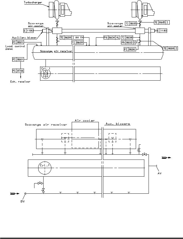
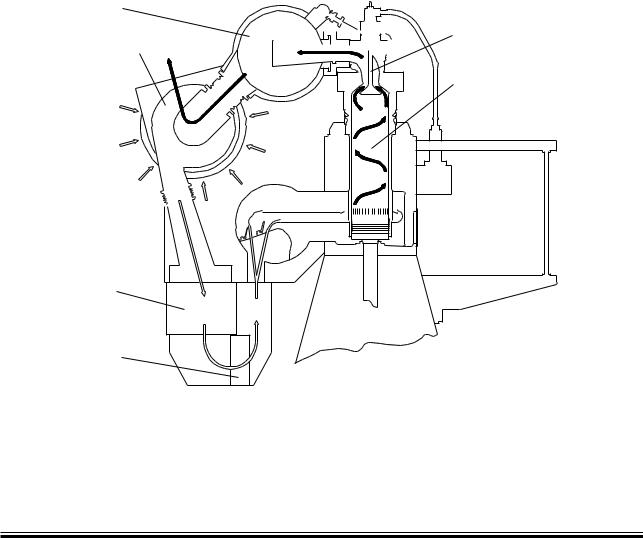
Scavenge air is supplied to the engine by two or more turbochargers, located on the exhaust side of the engine.
The compressor of the turbocharger draws air from the engine room, through an air filter, and the compressed air is cooled by the scavenge air cooler, one per turbocharger. The scavenge air cooler is provided with a water mist catcher, which prevents condensate water from being carried with the air into the scavenge air receiver and to the combustion chamber.
The scavenge air system (see Figs. 14.01.01 and 14.02.01) is an integrated part of the main engine.
The engine power figures and the data in the list of capacities are based on MCR at tropical conditions, i.e. a seawater temperature of 32 °C, or freshwater temperature of 36 °C, and an ambient air inlet temperature of 45 °C.
MAN B&W K108ME C6, K98MC/MC-C6/7, K98ME/ME C6/7, S90MC-C7/8, S90ME C7/8, K90MC-C6, K90ME9, K90ME C6/9, K80ME C9
Auxiliary Blowers
The engine is provided with from two to three electrically driven auxiliary blowers depending on the turbocharger make and number of cylinders. Between the scavenge air cooler and the scavenge air receiver, non return valves are fitted which close automatically when the auxiliary blowers start supplying the scavenge air.
The auxiliary blowers start operating consecutively before the engine is started and will ensure complete scavenging of the cylinders in the starting phase, thus providing the best conditions for a safe start.
During operation of the engine, the auxiliary blowers will start automatically whenever the engine load is reduced to about 30 40%, and will continue operating until the load again exceeds approximately 40 50%.
Emergency running
If one of the auxiliary blowers is out of function, the other auxiliary blower will function in the system, without any manual adjustment of the valves being necessary.
Page of 1
Control of the auxiliary blowers
The auxiliary blowers are fitted onto the main engine. The control system for the auxiliary blowers is integrated in the Engine Control System.
The starters are not included, they can be ordered as an option: 4 55 653.
The data for the scavenge air cooler is specified in the description of the cooling water system chosen.
For further information, please refer to our publication titled:
Influence of Ambient Temperature Conditions
The publication is available at: www.mandiesel.com under ‘Quicklinks’ → ‘Technical Papers’
2UNNINGæWITHæAUXILIARYæBLOWER
2UNNINGæWITHæTURBOCHARGER
178 44 70 5.1
Fig. 14.02.01: Scavenge air system
MAN B&W S90ME C7, K80ME C6
Scavenge Air Pipes
178 50 57 8.0
The item No. refer to ‘Guidance Values Automation’
Fig. 14.03.01: Scavenge air pipes
178 50 59 1.0
The letters refer to ‘List of flanges’
Fig. 14.03.02: Scavenge air space, drain pipes
MAN B&W K108ME C, K98ME/ME C, S90ME C, K90ME/ME C, S80ME C, K80ME C, S70ME C/ME GI, L70ME C, S65ME C/ME GI, S60ME C/ME GI, L60ME C
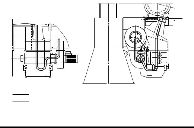
Electric Motor for Auxiliary Blower
The number of auxiliary blowers in a propulsion plant may vary depending on the actual amount of turbochargers as well as space requirements.
For typical engine configurations, the required power of the auxiliary blowers as well as the installed size of the electric motors are listed in Table 14.04.01.
Number of |
Number of auxiliary |
Required power/blower |
Installed power/blower |
cylinders |
blowers |
kW |
kW |
6 |
|
112 |
125 |
7 |
2 |
130 |
155 |
8 |
|
149 |
155 |
9 |
3 |
112 |
125 |
The installed power of the electric motors are based on a voltage supply of 3x440V at 60Hz. The electric motors are delivered with and fitted onto the engine.
Table 14.04.01: Electric motor for auxiliary blower
MAN B&W S90MC-C7, S90ME-C7
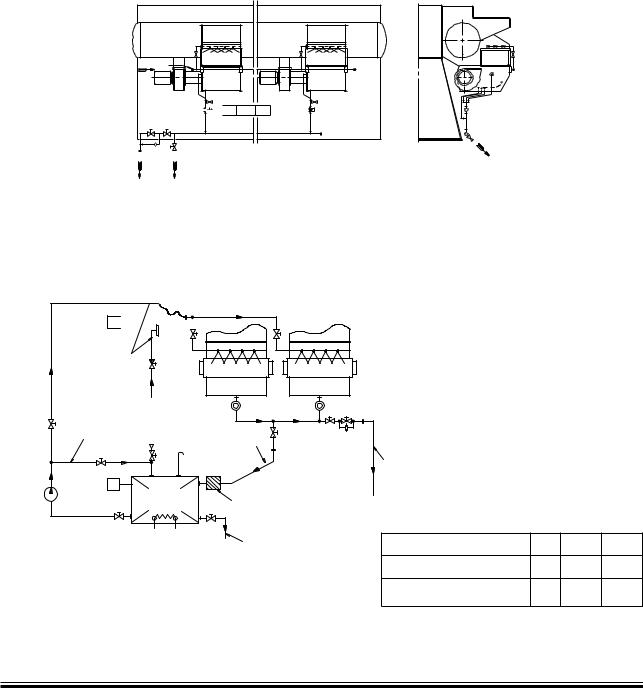
Scavenge Air Cooler Cleaning System
The air side of the scavenge air cooler can be cleaned by injecting a grease dissolvent media through ‘AK’ to a spray pipe arrangement fitted to the air chamber above the air cooler element.
Sludge is drained through ‘AL’ to the bilge tank and the polluted grease dissolvent returns from ‘AM’ through a filter, to the chemical cleaning tank. The cleaning must be carried out while the engine is at standstill. The piping delivered with and fitted on the engine is shown in Fig 14.05.01 ‘Air cooler cleaning pipes’.


 ,3ææ æ!(
!, !-
The letters refer to list of ‘Counterfflanges‘
The item no refer to ‘Guidance values automation’
178 50 60 1.0
Fig. 14.05.01: Air cooler cleaning pipes
Air Cooler Cleaning Unit, option: 4 55 665


 !+ 0)
!+ 0) 


$. æMM
!IRæCOOLER |
!IRæCOOLER |
æ&RESHWATER |
|
æ FROMæHYDROPHOR |
!, |
|
æ2ECIRCULATION |
$. æMM |
|
|
|
|
|
|
|
|
|
|
|
|
!- |
|
|
|
|
|
|
|
$. æMM |
|
|
|
|
4) |
|
|
|
|
|
#IRCULATIONæ |
#HEMICAL |
&ILTER |
|
|
|
|
PUMP |
CLEANINGæTANK |
$RAINæFROMæAIRæCOOLERæ |
|
|
|
|
|
æMMæMESHæSIZE |
CLEANINGæ æWATERæMISTæ |
|
|
|
|
|
|
CATCHERæINæAIRæCOOLER |
|
|
|
|
(EATINGæCOIL |
|
|
|
|
|
|
4OæFITæTHEæCHEMICAL |
æ3LUDGEæPUMPæSUCTION |
|
Cyl. |
6-8 |
9 |
|
MAKER SæREQUIREMENT |
|
Chemical tank capacity |
|
0.9 |
1.5 |
|
|
|
m3 |
|
|
|
Circulating pump capacity |
m3/h |
3 |
5 |
|
|
|
at 3 bar |
|
|
|
The letters refer to ‘List of flanges‘ |
|
|
|
|
|
|
|
|
|
|
|
079 61 05-4.1.0a |
Fig. 14.05.02: Air cooler cleaning system |
|
|
|
|
MAN B&W S90MC-C7/8, S90ME C7/8
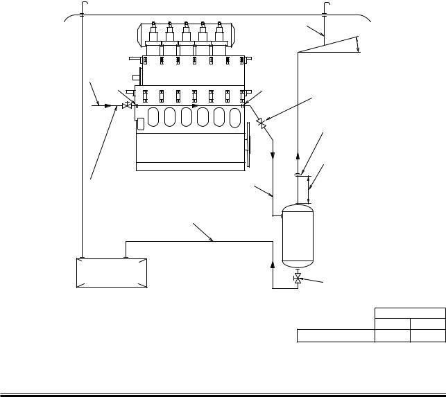
Scavenge Air Box Drain System
The scavenge air box is continuously drained through ‘AV’ to a small pressurised drain tank, from where the sludge is led to the sludge tank.
Steam can be applied through ‘BV’, if required, to facilitate the draining. See Fig. 14.06.01.
The continuous drain from the scavenge air box must not be directly connected to the sludge tank owing to the scavenge air pressure. The pressurised drain tank must be designed to withstand full scavenge air pressure and, if steam is applied, to withstand the steam pressure available.
Page of 1
Drain from water mist catcher
The drain line for the air cooler system is, during running, used as a permanent drain from the air cooler water mist catcher. The water is led through an orifice to prevent major losses of scavenge air. The system is equipped with a drain box with a level switch, indicating any excessive water level.
The system delivered with and fitted on the engine is shown in Fig. 14.03.02 Scavenge air space, drain pipes.
|
$ECK 2OOF |
|
|
|
$.æ æMM |
|
|
-IN æ ª |
$.æ æMM |
|
.ORMALLYæOPEN |
|
|
"6 |
!6 |
4OæBEæCLOSEDæINæCASEæOFæFIRE |
|
|
INæTHEæSCAVENGEæAIRæBOX |
|
|
/RIFICEæ æMM |
|
|
-IN æDISTANCE |
|
|
æMM |
3TEAMæINLETæPRESSUREæ ç æBAR |
$.æ æMM |
|
)FæSTEAMæISæNOTæAVAILABLE æ æBARæ |
|
|
COMPRESSEDæAIRæCANæBEæUSED |
|
|
$.æ æMM |
|
|
|
|
$RAIN |
|
|
TANK |
|
|
.ORMALLYæCLOSED |
3LUDGEæTANK |
|
4ANKæTOæBEæEMPTIED |
FORæFUELæOIL |
|
DURINGæSERVICEæWITHæ |
CENTRIFUGES |
|
VALVEæOPEN |
No. of cylinders
6 7-9
Drain tank capacity 0.4 m3 0.7 m3
The letters refer to list of ‘Counterflanges’
079 61 03-0.2.0
Fig. 14.06.01: Scavenge air box drain system
MAN B&W MAN B&W S90MC-C7/8, S90ME C7/8, S80ME C9


 %XHAUSTæVALVE 4URBOCHARGER


 RECEIVER