

s90mec7
.pdfMAN B&W |
8.05 |
|
|
Components for Lubricating Oil System
Lubricating oil pump
The lubricating oil pump can be of the displacement wheel, or the centrifugal type:
Lubricating oil viscosity, specified...75 cSt at 50 °C
Lubricating oil viscosity........... |
maximum 400 cSt * |
Lubricating oil flow............... |
see ‘List of capacities’ |
Design pump head....................................... |
4.6 bar |
Delivery pressure.......................................... |
4.6 bar |
Max. working temperature............................. |
70 °C |
*400 cSt is specified, as it is normal practice when starting on cold oil, to partly open the bypass valves of the lubricating oil pumps, so as to reduce the electric power requirements for the pumps.
The flow capacity must be within arange from 100 to 112% of the capacity stated.
The pump head is based on a total pressure drop across cooler and filter of maximum 1 bar.
The bypass valve shown between the main lubricating oil pumps Fig. 8.01.01 may be omitted in cases where the pumps have a built in bypass or if centrifugal pumps are used.
If centrifugal pumps are used, it is recommended to install a throttle valve at position ‘005’ to prevent an excessive oil level in the oil pan if the centrifugal pump is supplying too much oil to the engine.
During trials, the valve should be adjusted by means of a device which permits the valve to be closed only to the extent that the minimum flow area through the valve gives the specified lubricating oil pressure at the inlet to the engine at full normal load conditions. It should be possible to fully open the valve, e.g. when starting the engine with cold oil.
It is recommended to install a 25 mm valve (pos. 006), with a hose connection after the main lubricating oil pumps, for checking the cleanliness of the lubricating oil system during the flushing procedure. The valve is to be located on the underside of a horizontal pipe just after the discharge from the lubricating oil pumps.
Page of 3
Lubricating oil cooler
The lubricating oil cooler must be of the shell and tube type made of seawater resistant material, or a plate type heat exchanger with plate material of titanium, unless freshwater is used in a central cooling water system.
Lubricating oil viscosity, specified...75 cSt at 50 |
°C |
|||
Lubricating oil flow............... |
see ‘List of capacities’ |
|||
Heat dissipation................... |
see ‘List of capacities’ |
|||
Lubricating oil temperature, outlet cooler. |
.....45 |
°C |
||
Working pressure on oil side |
........................ |
4.6 bar |
||
Pressure drop on oil side............. |
|
maximum 0.5 bar |
||
Cooling water flow............... |
see ‘List of capacities’ |
|||
Cooling water temperature at inlet: |
|
|
||
seawater.......................................................... |
|
|
32 |
°C |
freshwater....................................................... |
|
|
36 |
°C |
Pressure drop on water side....... |
maximum 0.2 bar |
|||
The lubricating oil flow capacity must be within a range from 100 to 112% of the capacity stated.
The cooling water flow capacity must be within a range from 100 to 110% of the capacity stated.
To ensure the correct functioning of the lubricating oil cooler, we recommend that the seawater temperature is regulated so that it will not be lower than 10 °C.
The pressure drop may be larger, depending on the actual cooler design.
Lubricating oil temperature control valve
The temperature control system can, by means of a three way valve unit, by pass the cooler totally or partly.
Lubricating oil viscosity, specified.... |
75 cSt at 50 |
°C |
|
Lubricating oil flow............... |
see ‘List of capacities’ |
||
Temperature range, inlet to engine.......... |
40 47 |
°C |
|
MAN B&W S90MC-C7/8, S90ME C7/8, K90ME C6/9, S80ME C7/8/9
MAN Diesel |
198 42 37 7.3 |
|

MAN B&W |
8.05 |
|
|
Lubricating oil full flow filter
Lubricating oil flow............... |
see ‘List of capacities’ |
|
Working pressure.......................................... |
|
4.6 bar |
Test pressure.................... |
according to class rules |
|
Absolute fineness......................................... |
|
50 µm* |
Working temperature.............. |
|
approximately 45 °C |
Oil viscosity at working temp.............. |
90 100 cSt |
|
Pressure drop with clean filter..... |
maximum 0.2 bar |
|
Filter to be cleaned |
|
|
at a pressure drop....................... |
|
maximum 0.5 bar |
*The absolute fineness corresponds to a nominal fineness of approximately 30 µm at a retaining rate of 90%.
The flow capacity must be within a range from 100 to 112% of the capacity stated.
The full flow filter should be located as close as possible to the main engine.
If a double filter (duplex) is installed, it should have sufficient capacity to allow the specified full amount of oil to flow through each side of the filter at a given working temperature with a pressure drop across the filter of maximum 0.2 bar (clean filter).
Page of 3
If a filter with a back flushing arrangement is installed, the following should be noted:
•The required oil flow, specified in the ‘List of capacities’, should be increased by the amount of oil used for the back flushing, so that the lubricating oil pressure at the inlet to the main engine can be maintained during cleaning.
•If an automatically cleaned filter is installed, it should be noted that in order to activate the cleaning process, certain makes of filter require a higher oil pressure at the inlet to the filter than the pump pressure specified. Therefore, the pump capacity should be adequate for this purpose, too.
Flushing of lube oil system
Before starting the engine for the first time, the lubricating oil system on board has to be cleaned in accordance with MAN Diesel’s recommendations: ‘Flushing of Main Lubricating Oil System’, which is available on request.
MAN B&W S90MC-C7/8, S90ME C7/8, K90ME C6/9, S80ME C7/8/9
MAN Diesel |
198 42 37 7.3 |
|
MAN B&W |
8.05 |
|
|
Page of 3
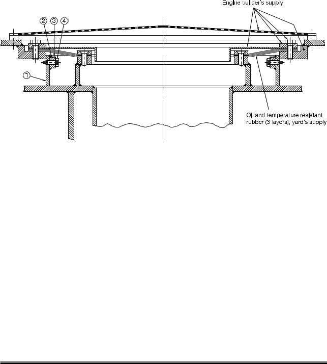
Lubricating oil outlet
A protecting ring position 1 4 is to be installed if required, by class rules, and is placed loose on the tanktop and guided by the hole in the flange.
In the vertical direction it is secured by means of screw position 4, in order to prevent wear of the rubber plate.
178 07 41 6.0 |
Fig. 8.05.01: Lubricating oil outlet
MAN B&W S90MC-C7/8, S90ME C7/8, K90ME C6/9, S80ME C7/8/9
MAN Diesel |
198 42 37 7.3 |
|
MAN B&W |
8.06 |
|
|
|
Page of 2 |
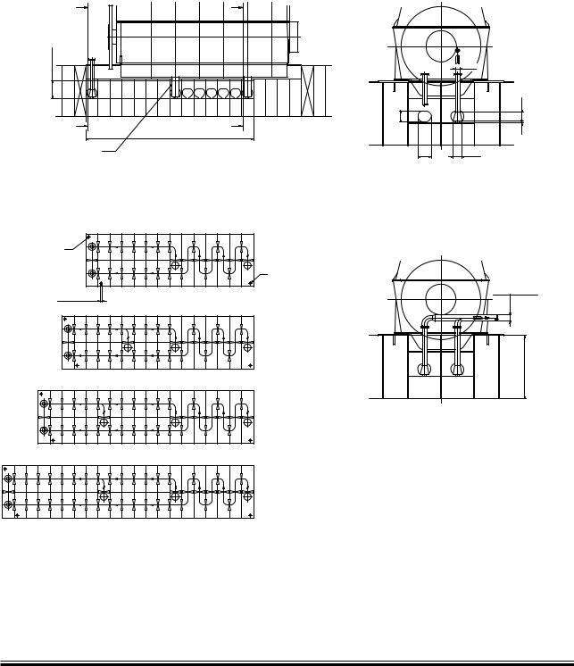
Lubricating Oil Tank
#YL æ |
#YL æ |
! |
" |
/ILæLEVELæWITHæ1M æ OILæINæBOTTOMæTANKæ ANDæWITHæPUMPSæ STOPPED
/, |
|
! |
" |
|
, |
/UTLETæFROMæENGINEæ æMMæ HAVINGæITSæBOTTOMæEDGEæBELOWæ THEæOILæLEVELæ TOæOBTAINæGASæSEALæ BETWEENæCRANKCASEæANDæ BOTTOMæTANK
MMæAIRæPIPE |
|
|
|
|
|
|
æCYL |
|
|
|
æMMæAIRæPIPE |
/ILæOUTLETæFROMæ |
|
|
|
TURBOCHARGER |
|
|
|
|
æCYL |
|
|
|
|
|
æCYL |
|
|
|
|
|
æCYL |
|
|
|
Fig. 8.06.01a: Lubricating oil tank, with cofferdam
3EEN¬FROM¬! !
|
|
|
|
|
|
|
|
|
|
3EEN¬FROM¬! !

 ,UB æOIL
PUMPæSUCTION
$ |
-IN æHEIGHTæ |
ACC æTOæCLASSæ |
REQUIREMENT |
178 19 92 5.1
MAN B&W S90MC C7/8, S90ME C7/8
MAN Diesel |
198 42 46 1.1 |
|

MAN B&W |
8.06 |
|
|
Note:
When calculating the tank heights, allowance has not been made for the possibility that a quantity of oil in the lubricating oil system outside the engine may be returned to the bottom tank, when the pumps are stopped.
Page of 2
If the system outside the engine is so designed that an amount of the lubricating oil is drained back to the tank, when the pumps are stopped, the height of the bottom tank indicated in Table 8.06.01b has to be increased to include this quantity. If space is limited, however, other solutions are possible.
Cylinder No. |
Drain at |
D0 |
H0 |
L |
OL |
Qm3 |
|
cylinder No. |
|||||||
|
|
|
|
|
|
||
6 |
2 5 |
350 |
1,230 |
11,200 |
1,130 |
45.5 |
|
7 |
2 5 7 |
375 |
1,280 |
12,800 |
1,180 |
53.0 |
|
8 |
2-5-8 |
400 |
1,345 |
14,400 |
1,245 |
63.0 |
|
9 |
2 5 8 |
425 |
1,425 |
16,800 |
1,320 |
78.0 |
Table 8.06.01b: Lubricating oil tank, with cofferdam
Lubricating oil tank operating conditions
The lubricating oil bottom tank complies with the rules of the classification societies by operation under the following conditions:
Angle of inclination, degrees
Athwartships |
Fore and aft |
||
Static |
Dynamic |
Static |
Dynamic |
15 |
22.5 |
5 |
7.5 |
MAN B&W S90MC C7/8, S90ME C7/8
MAN Diesel |
198 42 46 1.1 |
|
MAN B&W Diesel A/S |
8.07 |
|
|
Page 1 of 1
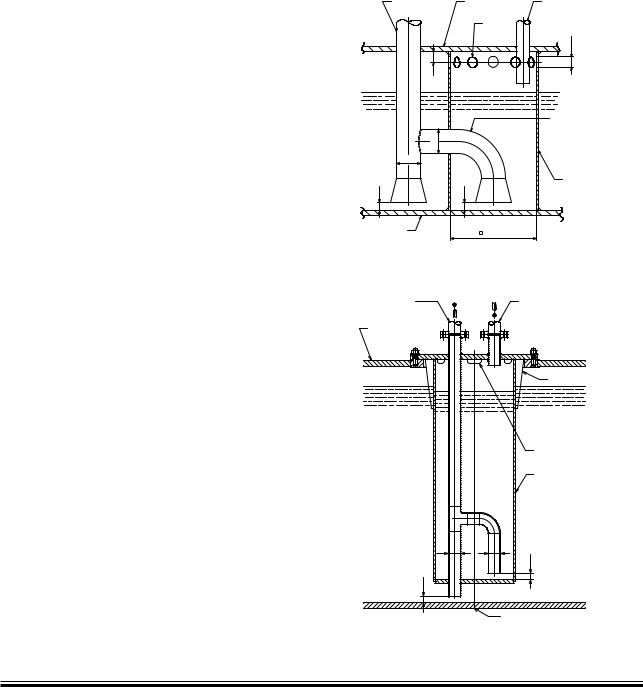
Crankcase Venting and Bedplate Drain Pipes
Deck
Inside diam. of pipe: 125 mm
To drain tank
To be laid with inclination
Venting from crankcase inside diam. of pipe: 80 mm
Hole diam.: 90 mm
To be equipped with flame screen if required by class rules
AR
This pipe to be delivered with the engine
Drain cowl
Inside diameter of drain pipe: 10 mm
198 97 10-1.3
Fig. 8.07.01: Crankcase venting
Drain turbocharger cleaning |
Cyl. 1 |
AE |
Drain from exh. side |
AE |
178 49 82-2.0 |
Fig. 8.07.02: Bedplate drain pipes
K108ME-C, K98ME/ME-C, S90ME-C, K90ME/ME-C |
198 42 59-3.1 |
MAN B&W |
8.08 |
|
|
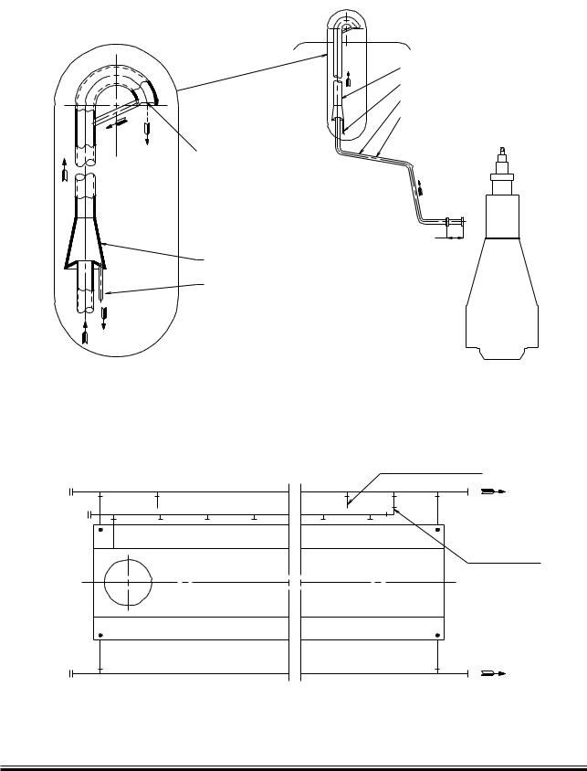
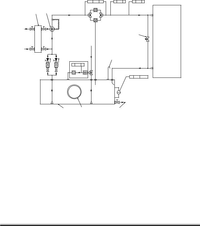
Hydraulic oil back flushing
The special suction arrangement for purifier suction in connection with the ME engine (Integrated system).
The back-flushing oil from the self cleaning 10 µm hydraulic control oil filter unit built onto the engine is contaminated and it is therefore not expedient to lead it directly into the lubricating oil sump tank.
The amount of back-flushed oil is large, and it is considered to be too expensive to discard it. Therefore, we suggest that the lubricating oil sump tank is modified for the ME engines in order not to have this contaminated lubricating
hydraulic control oil mixed up in the total amount of lubricating oil. The lubricating oil sump tank is designed with a small ‘back-flushing hydraulic control oil drain tank’ to which the back-flushed hydraulic control oil is led and from which the lubricating oil purifier can also suck.
This is explained in detail below and the principle is shown in Fig. 8.08.01. Three suggestions for the arrangement of the drain tank in the sump tank are shown in Fig. 8.08.02 illustrates another suggestion for a back-flushing oil drain tank.
The special suction arrangement for the purifier is consisting of two connected tanks (lubricating oil sump tank and back-flushing oil drain tank) and of this reason the oil level will be the same in both tanks, as explained in detail below.
The oil level in the two tanks will be equalizing through the ‘branch pipe to back-flushing oil drain tank’, see Fig. 8.08.01. As the pipes have the same diameters but a different length, the resistance is larger in the ‘branch pipe to back-flushing oil drain tank’, and therefore the purifier will suck primarily from the sump tank.
The oil level in the sump tank and the back-flush- ing oil drain tank will remain to be about equal because the tanks are interconnected at the top.
When hydraulic control oil is back-flushed from the filter, it will give a higher oil level in the backflushing hydraulic control oil drain tank and the purifier will suck from this tank until the oil level is the same in both tanks. After that, the purifier will suck from the sump tank, as mentioned above.
Page of 1
This special arrangement for purifier suction will ensure that a good cleaning effect on the lubrication oil is obtained.
If found profitable the back-flushed lubricating oil from the main lubricating oil filter (normally a 50 or 40 µm filter) can also be returned into the special back-flushing oil drain tank.
0URIFIER |
|
,UBRICATING |
"ACKçFLUSHEDæHYDRAULICæ |
SUCTIONæPIPE |
OILæTANKæTOP |
CONTROLæOILæFROMæSELFæ |
|
|
|
6ENTING |
CLEANING æ«MæFILTER |
|
|
8 |
|
|
|
HOLES |
|
|
|
|
|
|
|
|
|
/ILæLEVEL |
|
|
|
|
|
|
"RANCHæPIPEæTO |
|
|
|
BACKçFLUSHING |
3UMP |
$ |
|
HYDRAULICæCONTROLæ |
|
OILæDRAINæTANK |
||
TANK |
|
|
|
$ |
|
|
|
$ |
|
$ |
"ACKçFLUSHING |
|
HYDRAULICæCONTROL |
||
|
OILæDRAINæTANK |
||
|
|
|
|
,UBRICATING |
|
æ0IPEæ |
|
|
ORæææ X |
|
|
OILæTANKæBOTTOM |
|
|
|
|
|
|
|
|
|
|
178 52 49 6.1 |
Fig. 8.08.01: Back flushing servo oil drain tank
0URIFIER |
"ACKçFLUSHEDæHYDRAULICæ |
SUCTIONæPIPE |
CONTROLOILæFROMæSELF |
|
CLEANINGæ æ«MæFILTER |
,UBRICATING |
|
OILæTANKæTOP |
|
/ILæLEVEL |
3UPPORT |
|
|
|
6ENTINGæHOLES |
3UMP |
|
TANK |
"ACKçFLUSHING |
|
|
|
HYDRAULICæCONTROLæ |
|
OILæDRAINæTANK |
$ |
$ |
|
$ |
$ |
|
|
,UBRICATINGæOILæTANKæBOTTOM |
|
178 52 51 8.1 |
Fig. 8.08.02: Alternative design for the back flushing servo oil drain tank
MAN B&W ME/ME-B/ME C/ME GI engines, ME Engine Selection Guide
MAN Diesel |
198 48 29 7.2 |
|

MAN B&W |
8.09 |
|
|
|
Page of 4 |
Separate System for Hydraulic Control Unit
As an option, the engine can be prepared for the use of a separate hydraulic control oil system Fig. 8.09.01.
The separate hydraulic control oil system can be built as a unit, or be built streamlined in the engine room with the various components placed and fastened to the steel structure of the engine room.
The design and the dimensioning of the various components are based on the aim of having a reliable system that is able to supply low pressure oil to the inlet of the engine mounted high pressure hydraulic control oil pumps at a constant pressure, both at engine stand by and at various engine loads. The quality of the hydraulic control oil must fulfil the same grade as for our standard integrated lube/cooling/hydraulic control oil system, i.e. ISO 4406 XX/16/13 equivalent to NAS 1638 Class 7.
The hydraulic control oil system comprises:
1 Hydraulic control oil tank
2Hydraulic control oil pumps (one for stand by) 1 Pressure control valve
1 Hydraulic control oil cooler, water cooled by the low temperature cooling water
1 Three way valve, temperature controlled
1 Hydraulic control oil filter, duplex type or automatic self cleaning type
1 Hydraulic control oil fine filter with pump
1 Temperature indicator
1 Pressure indicator
2Level alarms Valves and cocks Piping.
Hydraulic control oil tank
The tank can be made of mild steel plate or be a part of the ship structure.
The tank is to be equipped with flange connections and the items listed below:
1 Oil filling pipe
1 Outlet pipe for pump suctions
1 Return pipe from engine
1 Drain pipe
1 Vent pipe.
The hydraulic control oil tank is to be placed at least 1 m below the hydraulic oil outlet flange, RZ.
Hydraulic control oil pump
The pump must be of the displacement type (e.g. gear wheel or screw wheel pump).
The following data is specified in Fig. 8.09.02:
•Pump capacity
•Pump head
•Delivery pressure
•Working temperature
•Oil viscosity range.
Pressure control valve
The valve is to be of the self operating flow controlling type, which bases the flow on the pre defined pressure set point. The valve must be able to react quickly from the fully closed to the fully open posi-
tion (tmax= 4 sec), and the capacity must be the same as for the hydraulic control oil low pressure
pumps. The set point of the valve has to be within the adjustable range specified on a separate drawing.
The following data is specified in Fig. 8.09.02:
•Flow rate
•Adjustable differential pressure range across the valve
•Oil viscosity range.
Hydraulic control oil cooler
The cooler must be of the plate heat exchanger or shell and tube type.
The following data is specified in Fig. 8.09.02:
•Heat dissipation
•Oil flow rate
•Oil outlet temperature
•Maximum oil pressure drop across the cooler
•Cooling water flow rate
•Water inlet temperature
•Maximum water pressure drop across the cooler.
Temperature controlled three way valve
The valve must act as a control valve, with an external sensor.
The following data is specified in Fig. 8.09.02:
•Capacity
•Adjustable temperature range
•Maximum pressure drop across the valve.
MAN B&W ME/ME-C/ME-GI engines
MAN Diesel |
198 48 52 3.2 |
|

MAN B&W |
8.09 |
|
|
Hydraulic control oil filter
The filter is to be of the duplex full flow type with manual change over and manual cleaning or of the automatic self cleaning type.
A differential pressure gauge is fitted onto the filter
The following data is specified in Fig. 8.09.02:
•Filter capacity
•Maximum pressure drop across the filter
•Filter mesh size (absolute)
•Oil viscosity
•Design temperature.
Off-line hydraulic control oil fine filter or purifier
Fig. 8.09.01
The off-line fine filter unit or purifier must be able to treat 15-20% of the total oil volume per hour.
The fine filter is an off-line filter and removes metallic and non-metallic particles larger than 0,8 µm as well as water and oxidation. The filter has a pertaining pump and is to be fitted on the top of the hydraulic control oil tank.
A suitable fine filter unit is:
Make: CJC, C.C. Jensen A/S, Svendborg, Denmark - www.cjc.dk.
For oil volume <10,000 litres:
HDU 27/-MZ-Z with a pump flow of 15-20% of the total oil volume per hour.
For oil volume >10,000 litres:
HDU 27/-GP-DZ with a pump flow of 15-20% of the total oil volume per hour.
Temperature indicator
The temperature indicator is to be of the liquid straight type.
Pressure indicator
The pressure indicator is to be of the dial type.
Page of 4
Level alarm
The hydraulic control oil tank has to have level alarms for high and low oil level.
Piping
The pipes can be made of mild steel. The design oil pressure is to be 10 bar.
The return pipes are to be placed vertical or laid with a downwards inclination of minimum 15°.
MAN B&W ME/ME-C/ME-GI engines
MAN Diesel |
198 48 52 3.2 |
|
MAN B&W |
8.09 |
|
|
Page |
of 4 |
|
|
0$3 !( |
0) ) |
4) ) |
%NGINE |
|
|
|
|
|
|
4EMPERATUREæ#ONTROL |
-ANUALæFILTER |
|
|
|
|
|
|
|
|
||
/ILæ#OOLER |
6ALVE |
!UTO |
|
|
29 |
|
|
|
|||
|
|
|
|
|
|
|
|
FILTER |
|
|
|
#OOLINGæWATER |
|
|
|
|
|
INLET |
|
|
|
|
|
|
|
|
4OæBEæPOSITIONEDæASæCLOSEæ |
|
|
|
|
|
ASæPOSSIBLEæTOæTHEæENGINE |
|
|
|
|
/ILæ&ILLING |
|
|
|
#OOLINGæWATER |
|
0IPE |
|
|
|
OUTLET |
|
|
|
|
|
|
|
0URIFIERæOR |
6ENTæ0IPE |
|
|
|
|
&INEæ&ILTERæ5NIT |
|
|
|
|
|
|
|
|
|
|
|
0) ) |
|
|
2: |
|
|
|
|
|
|
|
|
|
|
,3 !(æ!, |
|
/ILæ4ANK |
-ANHOLE |
$RAINæTOæ7ASTE |
|
|
|
|
|
/ILæ4ANK |
178 53 39 5.0
Fig. 8.09.01: Hydraulic control oil system, manual filter
MAN B&W ME/ME-C/ME-GI engines
MAN Diesel |
198 48 52 3.2 |
|