

s90mec7
.pdfMAN B&W |
7.01 |
|
|
The HCU has a leakage drain from the support console of clean fuel oil through ‘AD’.
The flow rate in litres is approximately as listed in Table 7.01.01.
|
Flow rate, |
Engine |
litres/cyl. h. |
K108ME-C, K98ME/ME-C, S90ME-C |
1.25 |
|
|
K90ME/ME-C, S/K80ME-C, S70ME-C/ |
|
ME-GI, L70ME-C, S65ME-C/ME-GI |
0.75 |
S/L60ME-C, S60ME-GI, S50ME-C, |
|
S50/40/35ME-B |
0.60 |
Table 7.01.01: Approximate flow in HCU leakage drain.
The main purpose of the drain ‘AF’ is to collect pure fuel oil from the fuel pumps as well as the unintentional leakage from the high pressure pipes. The drain oil is lead to a tank and can be pumped to the Heavy Fuel Oil service tank or to the settling tank.
The ‘AF’ drain is provided with a box for giving alarm in case of leakage in a high pressure pipes.
Page of 3
Heating of drain pipe
Owing to the relatively high viscosity of the heavy fuel oil, it is recommended that the drain pipe and the tank are heated to min. 50 °C, whereas the HFO pipes as basic are heated by steam through flanges ‘BX’ and ‘BF’.
The drain pipe between engine and tank can be heated by the jacket water, as shown in Fig. 7.01.01. ‘Fuel pipe heating’ as flange ‘BD’.
The size of the sludge tank is determined on the basis of the draining intervals, the classification society rules, and on whether it may be vented directly to the engine room.
This drained clean oil will, of course, influence the measured SFOC, but the oil is thus not wasted, and the quantity is well within the measuring accuracy of the flowmeters normally used.
For external pipe connections, we prescribe the following maximum flow velocities:
Marine diesel oil........................................... |
1.0 m/s |
Heavy fuel oil............................................... |
0.6 m/s |
The fuel viscosity is influenced by factors such as emulsification of water into the fuel for reducing the NOx emission. This is further described in section 7.06.
An emulsification arrangement for the main engine is described in our publication:
5510-0063 ‘Operation on Heavy Residual Fuels and Destilates. Guidelines for Fuels and Lubes’
This publication is available at our Internet address: www.mandiesel.com under ‘Quicklinks’ → ‘Technical Papers’, from where it can be downloaded.
MAN B&W ME/ME-B/ME C/ME GI engines
MAN Diesel |
198 42 28 2.6 |
|

MAN B&W |
7.02 |
|
|
Fuel oils
Marine diesel oil:
Marine diesel oil ISO 8217, Class DMB British Standard 6843, Class DMB Similar oils may also be used
Heavy fuel oil (HFO)
Most commercially available HFO with a viscosity below 700 cSt at 50 °C (7,000 sec. Redwood I at 100 °F) can be used.
For guidance on purchase, reference is made to ISO 8217:1996 and ISO 8217:2005, British Standard 6843 and to CIMAC recommendations regarding requirements for heavy fuel for diesel engines, fourth edition 2003, in which the maximum acceptable grades are RMH 700 and RMK
700. The above mentioned ISO and BS standards supersede BSMA 100 in which the limit was M9.
The data in the above HFO standards and specifications refer to fuel as delivered to the ship, i.e. before on-board cleaning.
In order to ensure effective and sufficient cleaning of the HFO, i.e. removal of water and solid contaminants, the fuel oil specific gravity at 15 °C (60 °F) should be below 0.991, unless modern types of centrifuges with adequate cleaning abilities are used.
Higher densities can be allowed if special treatment systems are installed.
Current analysis information is not sufficient for estimating the combustion properties of the oil. This means that service results depend on oil properties which cannot be known beforehand. This especially applies to the tendency of the oil to form deposits in combustion chambers, gas passages and turbines. It may, therefore, be necessary to rule out some oils that cause difficulties.
Page of 1
Guiding heavy fuel oil specification
Based on our general service experience we have, as a supplement to the above mentioned standards, drawn up the guiding HFO specification shown below.
Heavy fuel oils limited by this specification have, to the extent of the commercial availability, been used with satisfactory results on MAN B&W two stroke low speed diesel engines.
The data refers to the fuel as supplied i.e. before any on-board cleaning.
Guiding specification (maximum values)
Density at 15 °C |
kg/m3 |
|
< 1.010* |
Kinematic viscosity |
|
|
|
at 100 °C |
cSt |
|
< 55 |
at 50 °C |
cSt |
|
< 700 |
|
|
|
|
Flash point |
°C |
|
> 60 |
|
|
|
|
Pour point |
°C |
|
< 30 |
|
|
|
|
Carbon residue |
% (m/m) |
|
< 22 |
|
|
|
|
Ash |
% (m/m) |
|
< 0.15 |
|
|
|
|
Total sediment potential |
% (m/m) |
|
< 0.10 |
|
|
|
|
Water |
% (v/v) |
|
< 0.5 |
|
|
|
|
Sulphur |
% (m/m) |
|
< 4.5 |
|
|
|
|
Vanadium |
mg/kg |
|
< 600 |
|
|
|
|
Aluminum + Silicon |
mg/kg |
|
< 80 |
|
|
|
|
Equal to ISO 8217:2005 - RMK 700 |
|
||
/ CIMAC recommendation No. 21 - K700 |
|
||
|
|
||
* Provided automatic clarifiers are installed |
|
||
m/m = mass |
v/v = volume |
|
|
If heavy fuel oils with analysis data exceeding the above figures are to be used, especially with regard to viscosity and specific gravity, the engine builder should be contacted for advice regarding possible fuel oil system changes.
MAN B&W MC/MC-C, ME/ME-C/ME-GI/ME-B engines
MAN Diesel |
198 38 80-4.5 |
|
MAN B&W |
7.03 |
|
|
|
Page of 1 |
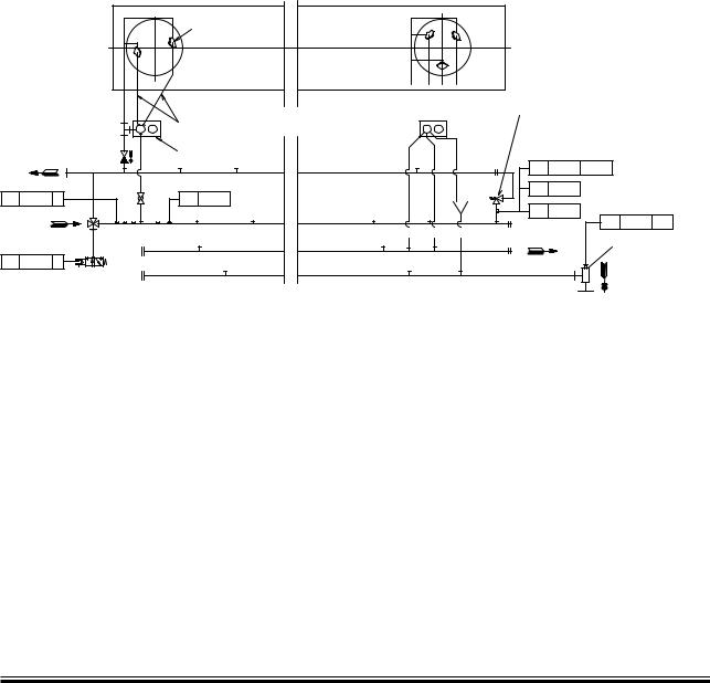
Fuel Oil Pipes and Drain Pipes
|
&ORæENGINES æ |
|
3 æ, 3 æ3 æ, 3 æ3 æ3 -%# |
|
#YL |
|
&UELæVALVES |
|
(IGHæPRESSUREæPIPES |
& |
(YDRAULICæ#YLINDERæUNIT |
|
|
4%ææææ ææææ) |
4)жжжжж |
8 |
|
:6ææææ æææ: |
|
The letters refer to ‘List of flanges’
The item No. refer to ‘Guidance values automation’
&ORæENGINES æ + æ+ æ+ æ+ -% #
"YçPASSæVALVE |
|
04жжжж жжжжж)ж!, |
|
0)жжжжж |
,OCALæOPERATIONæPANEL |
0)жжжжж |
|
|
,3ææææ ææææ!( |
!$ |
$RAINæBOXæWITHæ |
|
|
|
LEAKAGEæALARM |
|
!& 4OæSLUDGEæTANK |
178 50 29 2.2
Fig. 7.03.01: Fuel oil pipes
MAN B&W K108ME-C, K98ME/ME-C, S90ME-C, K90ME/ME-C, S80ME-C, K80ME-C, S70ME-C/ME-GI, L70ME-C, S65ME-C/ME-GI, S60ME-C/ME-GI, L60ME-C, ME Engine Selection Guide
MAN Diesel |
198 39 48 9.3 |
|
MAN B&W |
7.04 |
|
|
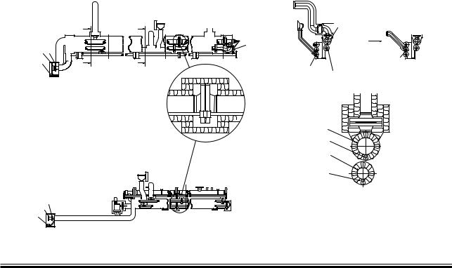
Fuel Oil Pipe Insulation
Insulation of fuel oil pipes and fuel oil drain pipes should not be carried out until the piping systems have been subjected to the pressure tests specified and approved by the respective classification society and/or authorities, Fig. 7.04.01.
The directions mentioned below include insulation of hot pipes, flanges and valves with a surface temperature of the complete insulation of maximum 55 °C at a room temperature of maximum 38 °C. As for the choice of material and, if required, approval for the specific purpose, reference is made to the respective classification society.
Fuel oil pipes
The pipes are to be insulated with 20 mm mineral wool of minimum 150 kg/m3 and covered with glass cloth of minimum 400 g/m2.
Fuel oil pipes and heating pipes together
Two or more pipes can be insulated with 30 mm wired mats of mineral wool of minimum 150 kg/m3 covered with glass cloth of minimum 400 g/m2.
Page of 3
Flanges and valves
The flanges and valves are to be insulated by means of removable pads. Flange and valve pads are made of glass cloth, minimum 400 g/m2, containing mineral wool stuffed to minimum 150 kg/m3.
Thickness of the pads to be: |
|
Fuel oil pipes................................................. |
20 mm |
Fuel oil pipes and heating pipes together.... |
30 mm |
The pads are to be fitted so that they lap over the pipe insulating material by the pad thickness. At flanged joints, insulating material on pipes should not be fitted closer than corresponding to the minimum bolt length.
Mounting
Mounting of the insulation is to be carried out in accordance with the supplier’s instructions.
&ORE
8 |
& |
"& æ"8 |
|
|
|
|
!ç! |
|
|
|
"ç" |
! |
#YL æ |
" |
&UELæOILæINLET |
|
|||
|
|
&UNNELæANDæ |
% |
|
|
|
|
|
|
PIPEæ MM |
&UELæOILæDRAIN |
|
|
NOTæTOæBEæINSULATED |
|
! |
|
" |
UMBRELLA |
|
|
$RAINæPIPEæFUELæOIL |
&UELæOILæOUTLET |
|
|
|
!ç!
|
&UELæOILæINLET |
|
(EATINGæPIPE |
% |
&UELæOILæOUTLET |
|
|
3EENæFROMæCYL æSIDE |
(EATINGæPIPE |
|
|
#YL æ |
&ORE |
!$ |
|
!& |
|
"$ |
|
Fig. 7.04.01: Details of fuel oil pipes insulation, option: 4 35 121. Example from 98-50 MC engine |
178 50 65 0.2 |
MAN B&W MC/MC C, ME/ME-C/ME-GI/ME-B engines, Engine Selection Guide
MAN Diesel |
198 40 51 8.3 |
|
MAN B&W |
7.04 |
|
|
Page |
of 3 |
Heat Loss in Piping
Temperature difference between pipe and room °C 


|
|
|
|
|
|
|
|
|
s |
|
|
|
|
|
|
|
|
s |
|
|
|
|
|
|
|
|
e |
|
|
|
|
|
|
|
|
n |
|
|
|
|
|
|
|
|
k |
|
|
|
|
|
|
|
|
ic |
|
|
|
|
|
|
|
|
h |
|
|
|
|
|
|
|
|
t |
|
|
|
|
|
|
|
|
|
n |
|
|
|
|
|
|
|
|
io |
|
|
|
|
|
|
|
|
|
t |
|
|
|
|
|
|
|
|
|
la |
|
|
|
|
|
|
|
|
|
u |
|
|
|
|
|
|
|
|
s |
|
|
|
|
|
|
|
|
|
In |
|
|
|
|
|
|
|
|
|
20
30 40
50 |
60 |
|
|
|
|
70 |
|
|
|
|
|
|
|
|
|
|
80 |
|
|
|
|
90 |
0 |
|
|
|
10 |
120 |
|
|
|
|
|
|
160 200
Heat loss watt/meter pipe
Pipe diameter mm
178 50 60 2.0
Fig. 7.04.02: Heat loss/Pipe cover
MAN B&W MC/MC C, ME/ME-C/ME-GI/ME-B engines, Engine Selection Guide
MAN Diesel |
198 40 51 8.3 |
|
MAN B&W |
7.04 |
|
|
|
Page of 3 |
Fuel Oil Pipe Heat Tracing
The steam tracing of the fuel oil pipes is intended to operate in two situations:
1.When the circulation pump is running, there will be a temperature loss in the piping, see Fig. 7.04.02. This loss is very small, therefore tracing in this situation is only necessary with very long fuel supply lines.
2.When the circulation pump is stopped with heavy fuel oil in the piping and the pipes have cooled down to engine room temperature, as it is not possible to pump the heavy fuel oil. In this situation the fuel oil must be heated to pumping temperature of about 50 ºC.
To heat the pipe to pumping level we recommend to use 100 watt leaking/meter pipe.
#YL æ
&UELæVALVE |
|
|
3HOCKæABSORBER |
$RAINæCYL æFRAME |
|
&UELæPUMP |
3EEæDRAWING |
|
&UELæOILæPIPESæINSULATION |
||
|
& 


 "8
"8 


8 "& 


, &RESHæCOOLING WATERæOUTLET
!& !$ "$
The letters refer to list of ‘Counterflanges’
Fig. 7.04.03: Fuel oil pipe heat tracing
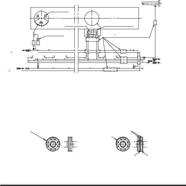
Fuel Oil and Lubricating Oil Pipe Spray Shields
In order to fulfil IMO regulations, fuel oil and lubricating oil pipe assemblies are to be enclosed by spray shields as shown in Fig. 7.04.04a and b.
178 50 62 5.0
To avoid leaks, the spray shields are to be installed after pressure testing of the pipe system.
!NTIçSPLASHINGæTAPE |
#LAMPINGæBANDS |
/VERLAP
4HEæTAPEæISæTOæBEæWRAPPEDæINæACCORDANCEæWITHæ |
0LATEæ æMM æTHICKNESS |
4HEæWIDTHæISæTOæCOVERæ |
THEæMAKERSæINSTRUCTIONæFORæCLASSæAPPROVAL |
|
HEADæOFæBOLTSæANDæNUTS |
|
|
178 52 55 5.2 |
Fig. 7.04.04a: Spray Shields by anti-splashing tape |
Fig. 7.04.04b: Spray Shields by clamping bands |
|
MAN B&W K108ME-C6, K98MC/MC C, K98ME/ME-C, S90MC-C, S90ME-C, K90MC-C, K90ME/ME-C, S80MC/MC-C, S80ME-C, K80MC-C, K80ME-C, S70MC, S/L70MC-C, S/L70ME-C, S60MC, S/L60MC-C, S/L60ME-C, S60ME-B, S50MC, Engine Selection Guide
MAN Diesel |
198 67 68-4.0 |
|

MAN B&W |
7.05 |
|
|
Components for fuel oil system
Fuel oil centrifuges
The manual cleaning type of centrifuges are not to be recommended, neither for attended machinery spaces (AMS) nor for unattended machinery spaces (UMS). Centrifuges must be self cleaning, either with total discharge or with partial discharge.
Distinction must be made between installations for:
•Specific gravities < 0.991 (corresponding to ISO 8217 and British Standard 6843 from RMA to RMH, and CIMAC from A to H grades
•Specific gravities > 0.991 and (corresponding to CIMAC K grades).
For the latter specific gravities, the manufacturers have developed special types of centrifuges, e.g.:
Alfa Laval........................................................ |
Alcap |
Westfalia....................................................... |
Unitrol |
Mitsubishi............................................... |
E Hidens II |
The centrifuge should be able to treat approximately the following quantity of oil:
0.23 litres/kWh = 0.17 litres/BHPh
This figure includes a margin for:
•Water content in fuel oil
•Possible sludge, ash and other impurities in the fuel oil
•Increased fuel oil consumption, in connection with other conditions than ISO standard condition
•Purifier service for cleaning and maintenance.
The size of the centrifuge has to be chosen according to the supplier’s table valid for the selected viscosity of the Heavy Fuel Oil. Normally, two centrifuges are installed for Heavy Fuel Oil (HFO), each with adequate capacity to comply with the above recommendation.
Page of 3
A centrifuge for Marine Diesel Oil (MDO) is not a must, but if it is decided to install one on board, the capacity should be based on the above recommendation, or it should be a centrifuge of the same size as that for lubricating oil.
The Nominal MCR is used to determine the total installed capacity. Any derating can be taken into consideration in border line cases where the centrifuge that is one step smaller is able to cover
Specified MCR.
Fuel oil supply pump
This is to be of the screw or gear wheel type.
Fuel oil viscosity, specified.... |
up to 700 cSt at 50 |
°C |
Fuel oil viscosity maximum....................... |
1000 cSt |
|
Pump head....................................................... |
4 bar |
|
Fuel oil flow.......................... |
see ‘List of capacities’ |
|
Delivery pressure............................................. |
4 bar |
|
Working temperature.................................... |
100 |
°C |
Minimum temperature.................................... |
50 |
°C |
The capacity stated in ‘List of capacities’ is to be fulfilled with a tolerance of: ÷0% to +15% and shall also be able to cover the back flushing, see ‘Fuel oil filter’.
Fuel oil circulating pump
This is to be of the screw or gear wheel type.
Fuel oil viscosity, specified.... |
up to 700 cSt at 50 °C |
Fuel oil viscosity normal................................ |
20 cSt |
Fuel oil viscosity maximum....................... |
1000 cSt |
Fuel oil flow.......................... |
see ‘List of capacities’ |
Pump head....................................................... |
6 bar |
Delivery pressure........................................... |
10 bar |
Working temperature.................................... |
150 °C |
The capacity stated in ‘List of capacities’ is to be fulfilled with a tolerance of: ÷0% to +15% and shall also be able to cover the back flushing, see ‘Fuel oil filter’.
Pump head is based on a total pressure drop in filter and preheater of maximum 1.5 bar.
MAN B&W MC/MC-C, ME/ME-B/ME C/ME GI engines
MAN Diesel |
198 39 51 2.3 |
|
MAN B&W |
7.05 |
|
|
|
|
|
|
|
!PPROXIMATEæVISCOSITY |
|||
|
|
|
|
|
|
AFTERæHEATER |
||
4EMPERATURE |
|
|
|
|
|
C3T |
SEC |
|
AFTERæHEATER |
|
|
|
|
|
|
|
2W |
# |
|
|
|
|
|
|
|
|
|
|
|
|
|
|
|
||
|
|
|
|
|
|
|
|
|
|
|
.ORMALæHEATINGæLIMIT |
|
|
|
|
|
|
|
|
|
|
|
|
|||
|
|
|
|
|
|
|
|
|
|
|
|
|
|
|
|
|
|
|
|
|
|
|
|
|
|
|
|
|
|
|
|
|
|
||
|
|
|
|
|
|
|
|
|
|
|
|
|
|
|
|
|
|
|
|
|
|
|
|
|
|
|
|
|
|
|
|
|
|
|
|
|
|
|
|
|
|
|
||
|
|
|
|
|
|
|
|
|
|
|
|
|
|
|
|
|
|
|
|
|
|
|
|
|
|
|
|
|
|
|
|
|
|
|
|
|
|
|
|
|
|
|
|
|
|
|
|
|
|
|
|
|
|
|
|
!PPROXIMATEæPUMPINGæLIMIT |
|
|
|
|
||
|
|
|
|
|
|
|
|
|
|
|
|
|
|
|
|
|
|
|
|
|
|
|
|
|
|
|
|
|
|
|
|
|
|
C34 # |
|
|
|
|
|
|
|
C34 # |
||
|
|
|
|
|
|
SEC 2W æ& |
||
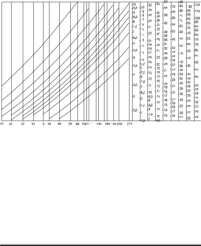
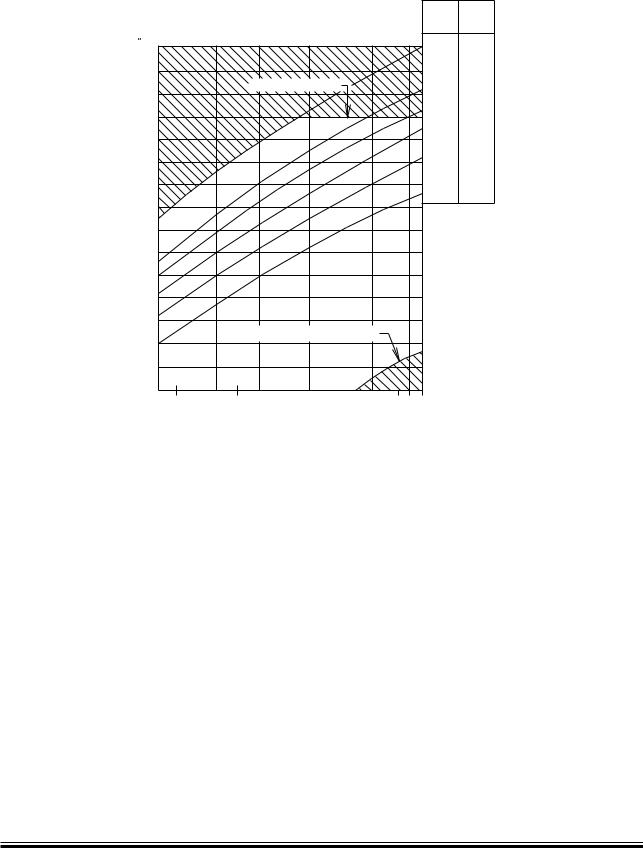
Fig. 7.05.01: Fuel oil heating chart
Page of 3
178 06 28 0.1
Fuel oil heater
The heater is to be of the tube or plate heat exchanger type.
The required heating temperature for different oil viscosities will appear from the ‘Fuel oil heating chart’. The chart is based on information from oil suppliers regarding typical marine fuels with viscosity index 70 80.
Since the viscosity after the heater is the controlled parameter, the heating temperature may vary, depending on the viscosity and viscosity index of the fuel.
Recommended viscosity meter setting is 10 15 cSt.
Fuel oil viscosity specified |
.... up to 700 cSt at 50°C |
||
Fuel oil flow..................................... |
|
see capacity of |
|
|
fuel oil circulating pump |
||
Heat dissipation................... |
see ‘List of capacities’ |
||
Pressure drop on fuel oil side......... |
maximum 1 bar |
||
Working pressure........................................... |
|
10 bar |
|
Fuel oil inlet temperature................. |
|
approx. 100 |
°C |
Fuel oil outlet temperature............................ |
|
150 |
°C |
Steam supply, saturated........................... |
|
7 bar abs |
|
To maintain a correct and constant viscosity of the fuel oil at the inlet to the main engine, the steam supply shall be automatically controlled, usually based on a pneumatic or an electrically controlled system.
MAN B&W MC/MC-C, ME/ME-B/ME C/ME GI engines
MAN Diesel |
198 39 51 2.3 |
|
MAN B&W |
7.05 |
|
|
Fuel oil filter
The filter can be of the manually cleaned duplex type or an automatic filter with a manually cleaned bypass filter.
If a double filter (duplex) is installed, it should have sufficient capacity to allow the specified full amount of oil to flow through each side of the filter at a given working temperature with a max. 0.3 bar pressure drop across the filter (clean filter).
If a filter with backflushing arrangement is installed, the following should be noted. The required oil flow specified in the ‘List of capacities’, i.e. the delivery rate of the fuel oil supply pump and the fuel oil circulating pump, should be increased by the amount of oil used for the backflushing, so that the
fuel oil pressure at the inlet to the main engine can be maintained during cleaning.
In those cases where an automatically cleaned filter is installed, it should be noted that in order to activate the cleaning process, certain makers of filters require a greater oil pressure at the inlet to the filter than the pump pressure specified.
Therefore, the pump capacity should be adequate for this purpose, too.
The fuel oil filter should be based on heavy fuel oil of: 130 cSt at 80 °C = 700 cSt at 50 °C = 7000 sec Redwood I/100 °F.
Fuel oil flow.......................... |
see ‘List of capacities’ |
|
Working pressure........................................... |
|
10 bar |
Test pressure...................... |
according to class rule |
|
Absolute fineness.......................................... |
|
50 µm |
Working temperature................... |
maximum 150 °C |
|
Oil viscosity at working temperature............. |
15 cSt |
|
Pressure drop at clean filter........ |
maximum 0.3 bar |
|
Filter to be cleaned at a pressure |
|
|
drop at ........................................ |
maximum 0.5 bar |
|
Note:
Absolute fineness corresponds to a nominal fineness of approximately 30 µm at a retaining rate of 90%.
The filter housing shall be fitted with a steam jacket for heat tracing.
Page of 3
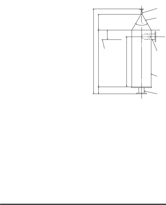
Fuel oil venting box
The design is shown on ‘Fuel oil venting box’, see Fig. 7.05.02
|
|
Vent pipe, |
|
|
nominal: D |
|
|
Cone |
|
H |
60 |
|
|
|
|
|
200 |
|
|
Top of fuel oil |
|
|
service tank |
H4 |
|
Inlet pipe, |
|
|
|
|
H2 |
nominal: D2 |
|
|
|
|
|
H5 |
|
|
Pipe, |
|
|
nominal: D1 |
|
H1 |
|
|
|
Outlet pipe, |
|
|
nominal: D2 |
|
|
178 38 39 3.2 |
Flow m3/h |
|
|
|
Dimensions in mm |
|
|
|
|||
Q (max.)* |
D1 |
D2 |
D3 |
|
H1 |
H2 |
|
H3 |
H4 |
H5 |
|
|
|
|
|
|
|
|
|
|
|
11.5 |
400 |
90 |
15 |
|
150 |
1,200 |
|
333.5 |
1,800 |
1,100 |
|
|
|
|
|
|
|
|
|
|
|
19.5 |
400 |
125 |
15 |
|
150 |
1,200 |
|
333.5 |
1,800 |
1,100 |
|
|
|
|
|
|
|
|
|
|
|
* The actual maximum flow of the fuel oil circulation pump
Fig. 07.05.02: Fuel oil venting box
Flushing of the fuel oil system
Before starting the engine for the first time, the system on board has to be flushed in accordance with MAN B&W’s recommendations ‘Flushing of Fuel Oil System’ which is available on request.
MAN B&W S90ME C, S80ME C, K80ME C
MAN Diesel |
198 41 17 9.0 |
|

MAN B&W |
7.06 |
|
|
Water In Fuel Emulsification
The emulsification of water into the fuel oil reduces the NOx emission with about 1% per 1% water added to the fuel up to about 20% without modification of the engine fuel injection equipment.
A Water In Fuel emulsion (WIF) mixed for this purpose and based on Heavy Fuel Oil (HFO) is stable for a long time, whereas a WIF based on Marine Diesel Oil is only stable for a short period of time unless an emulsifying agent is applied.
As both the MAN B&W two stroke main engine and the MAN Diesel GenSets are designed to run on emulsified HFO, it can be used for a common system.
It is supposed below, that both the main engine and GenSets are running on the same fuel, either HFO or a homogenised HFO-based WIF.
Special arrangements are available on request for a more sophisticated system in which the GenSets can run with or without a homogenised HFObased WIF, if the main engine is running on that.
Please note that the fuel pump injection capacity shall be confirmed for the main engine as well as the GenSets for the selected percentage of water in the WIF.
Temperature and pressure
When water is added by emulsification, the fuel viscosity increases. In order to keep the injection viscosity at 10-15 cSt and still be able to operate on up to 700 cSt fuel oil, the heating temperature has to be increased to about 170 °C depending on the water content.
The higher temperature calls for a higher pressure to prevent cavitation and steam formation in the system. The inlet pressure is thus set to 13 bar.
In order to avoid temperature chock when mixing water into the fuel in the homogeniser, the water inlet temperature is to be set to 70 90 °C.
Page of 2
Safety system
In case the pressure in the fuel oil line drops, the water homogenised into the Water In Fuel emulsion will evaporate, damaging the emulsion and creating supply problems. This situation is avoided by installing a third, air driven supply pump, which keeps the pressure as long as air is left in the tank ‘S’, see Fig. 7.06.01.
Before the tank ‘S’ is empty, an alarm is given and the drain valve is opened, which will drain off the WIF and replace it with HFO or diesel oil from the service tank.
The drain system is kept at atmospheric pressure, so the water will evaporate when the hot emulsion enters the safety tank. The safety tank shall be designed accordingly.
Impact on the auxiliary systems
Please note that if the engine operates on Water In Fuel emulsion (WIF), in order to reduce the NOx emission, the exhaust gas temperature will decrease due to the reduced air / exhaust gas ratio and the increased specific heat of the exhaust gas.
Depending on the water content, this will have an impact on the calculation and design of the following items:
•Freshwater generators
•Energy for production of freshwater
•Jacket water system
•Waste heat recovery system
•Exhaust gas boiler
•Storage tank for freshwater
For further information about emulsification of water into the fuel and use of Water In Fuel emulsion (WIF), please refer to our publication titled:
Exhaust Gas Emission Control Today and
Tomorrow
The publication is available at: www.mandiesel.com under ‘Quicklinks’ → ‘Technical Papers
MAN B&W MC/MC-C, ME/ME-C/ME-GI/ME-B engines
MAN Diesel |
198 38 82 8.3 |
|