

s90mec7
.pdfMAN B&W |
12.07 |
|
|
|
Page of 2 |
Components for Jacket Cooling Water System
Jacket water cooling pump
The pumps are to be of the centrifugal type.
Jacket water flow................. |
see ‘List of capacities’ |
Pump head.................................................... |
3.0 bar |
Delivery pressure.................... |
depends on position |
|
of expansion tank |
Test pressure...................... |
according to class rule |
Working temperature,.............. 80 °C, max. 100 °C The capacity must be met at a tolerance of 0% to +10%.
The stated capacities cover the main engine only. The pump head of the pumps is to be determined based on the total actual pressure drop across the cooling water system.
Freshwater generator
If a generator is installed in the ship for production of freshwater by utilising the heat in the jacket water cooling system it should be noted that the actual available heat in the jacket water system is lower than indicated by the heat dissipation figures given in the ‘List of capacities.‘ This is because the latter figures are used for dimensioning the jacket water cooler and hence incorporate a safety margin which can be needed when the engine is operating under conditions such as, e.g. overload. Normally, this margin is 10% at nominal MCR.
The calculation of the heat actually available at specified MCR for a derated diesel engine is stated in chapter 6 ‘List of capacities‘.
For illustration of installation of fresh water generator see Fig. 12.05.01.
Jacket water thermostatic valve
The temperature control system is equipped with a three way valve mounted as a diverting valve, which by pass all or part of the jacket water around the jacket water cooler.
The sensor is to be located at the outlet from the main engine, and the temperature level must be adjustable in the range of 70 90 °C.
Jacket water preheater
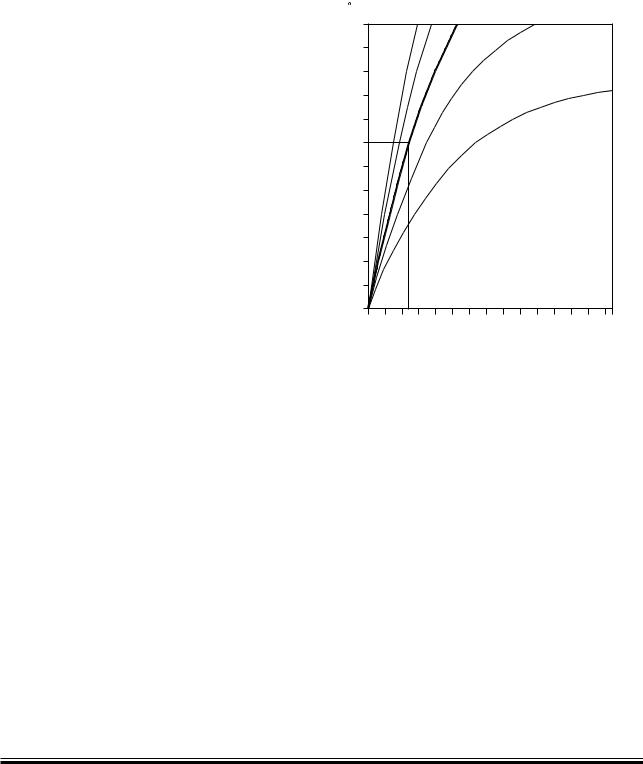
When a preheater, see Fig. 12.05.01, is installed in the jacket cooling water system, its water flow, and thus the preheater pump capacity, should be about 10% of the jacket water main pump capacity.
Based on experience, it is recommended that the pressure drop across the preheater should be approx. 0.2 bar. The preheater pump and main pump should be electrically interlocked to avoid the risk of simultaneous operation.
The preheater capacity depends on the required preheating time and the required temperature increase of the engine jacket water. The temperature and time relations are shown in Fig. 12.08.01.
In general, a temperature increase of about 35 °C (from 15 °C to 50 °C) is required, and a preheating time of 12 hours requires a preheater capacity of about 1% of the engine`s nominal MCR power.
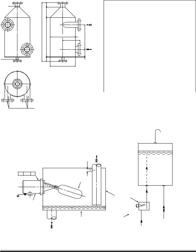
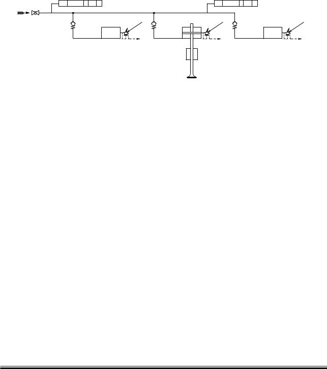
Deaerating tank
Design and dimensions of the deaerating tank are shown in Fig. 12.07.01 ‘Deaerating tank‘ and the corresponding alarm device is shown in Fig. 12.07.02 ‘Deaerating tank, alarm device‘.
Expansion tank
The total expansion tank volume has to be approximate 10% of the total jacket cooling water amount in the system.
Fresh water treatment
The MAN Diesel recommendations for treatment of the jacket water/freshwater are available on request.
MAN B&W MC/MC C, ME/ME-B/ME C/ME GI engines
MAN Diesel |
198 40 56 7.3 |
|
MAN B&W |
12.07 |
|
|
Deaerating tank
*
+
|
|
|
" |
|
|
& |
|
|
( |
|
|
! |
' |
% |
|
|
|
|
|
$ |
|
|
# |
) |
|
|
$IAMETERæCORRESPONDINGæTO PIPEæDIAMETERæINæENGINEæROOM
178 06 27 9.2
Fig. 12.07.01: Deaerating tank, option: 4 46 640
Page of 2
Deaerating tank dimensions
Tank size |
0.16 m3 |
0.70 m3 |
Max. jacket water capacity |
300 m3/h |
700 m3/h |
|
Dimensions in mm |
|
|
|
|
Max. nominal diameter |
200 |
300 |
|
|
|
A |
800 |
1,200 |
|
|
|
B |
210 |
340 |
|
|
|
C |
5 |
8 |
|
|
|
D |
150 |
200 |
|
|
|
E |
500 |
800 |
|
|
|
F |
1,195 |
1,728 |
|
|
|
G |
350 |
550 |
|
|
|
øH |
500 |
800 |
|
|
|
øI |
520 |
820 |
|
|
|
øJ |
ND 80 |
ND 100 |
|
|
|
øK |
ND 50 |
ND 80 |
|
|
|
ND: Nominal diameter
Working pressure is according to actual piping arrangement.
In order not to impede the rotation of water, the pipe connection must end flush with the tank, so that no internal edges are protruding.
,3æææ æææ!,
,EVELæSWITCH
|
|
,EVELæSWITCHæFLOAT |
|
|
!LARMæDEVICE |
,EVELæSWITCHæFLOAT |
,EVELæSWITCHæFLOAT |
INæPOSITIONæFORæALARM |
INæNORMALæPOSITIONæçæNOæALARM |
%XPANSIONæTANK |
&ROMæDEAERATINGæTANK
198 97 09 1.1
Fig. 12.07.02: Deaerating tank, alarm device, option: 4 46 645
MAN B&W K98MC/MC-C6/7, K98ME/ME C6/7, S90MC-C7/8, S90ME C7/8, K90MC-C6, K90ME9, K90ME C6/9, S80MC6, K80MC-C6, K80ME C6/9
MAN Diesel |
198 40 61 4.2 |
|
MAN B&W |
12.08 |
|
|
Temperature at Start of Engine
In order to protect the engine, some minimum temperature restrictions have to be considered before starting the engine and, in order to avoid corrosive attacks on the cylinder liners during starting.
Normal start of engine
Normally, a minimum engine jacket water temperature of 50 °C is recommended before the engine is started and run up gradually to 90% of specified MCR speed.
For running between 90% and 100% of specified MCR speed, it is recommended that the load be increased slowly – i.e. over a period of 30 minutes.
Start of cold engine
In exceptional circumstances where it is not possible to comply with the above-mentioned recommendation, a minimum of 20 °C can be accepted before the engine is started and run up slowly to 90% of specified MCR speed.
However, before exceeding 90% specified MCR speed, a minimum engine temperature of 50 °C should be obtained and, increased slowly – i.e. over a period of at least 30 minutes.
The time period required for increasing the jacket water temperature from 20 °C to 50 °C will depend on the amount of water in the jacket cooling water system, and the engine load.
Note:
The above considerations are based on the assumption that the engine has already been well run in.
Page of 1
4EMPERATURE |
|
|
|
|
|
0REHEATER |
|
INCREASEæOFæ |
|
|
|
|
|
CAPACITYæIN |
|
JACKETæWATER |
|
|
|
|
|
|
æOFæNOMINAL |
|
|
|
|
|
|
-#2æPOWER |
|
# |
|
|
|
|
|
|
|
|
|
|
|
|
|
|
|
|
|
|
|
|
|
|
|
|
|
|
|
|
|
|
|
|
|
|
|
|
|
|
|
|
|
|
|
|
|
|
|
|
|
|
|
|
|
|
|
|
|
|
|
|
|
|
|
|
|
|
|
|
|
|
|
|
|
|
|
|
|
|
|
|
|
|
|
|
|
|
|
|
|
|
|
|
|
|
HOURS |
|
|
|
|
|
|
0REHEATINGæTIME |
|
|
|
|
|
|
|
|
178 16 63 1.0 |
Fig. 12.08.01: Jacket water preheater
Preheating of diesel engine
Preheating during standstill periods
During short stays in port (i.e. less than 4 5 days), it is recommended that the engine is kept preheated, the purpose being to prevent temperature variation in the engine structure and corresponding variation in thermal expansions and possible leakages.
The jacket cooling water outlet temperature should be kept as high as possible and should – before starting up – be increased to at least 50 °C, either by means of cooling water from the auxiliary engines, or by means of a built in preheater in the jacket cooling water system, or a combination.
MAN B&W MC/MC C, ME/ME-B/ME C/ME GI engines
MAN Diesel |
198 39 86 0.2 |
|

MAN B&W
Starting and Control Air
13
MAN Diesel
MAN B&W |
13.01 |
|
|
|
Page of 1 |
Starting and Control Air Systems


 2EDUCINGæVALVEæ æ æ
4OæFUELæVALVEæ |
TESTINGæUNIT |
/ILæ æWATER SEPARATOR 
 4OæBILGE
3TARTINGæAIRæCOMPRESSORSæ æ
|
|
2EDUCINGæSTATIONæ æ æ |
|
|
|
|
|
3TARTINGæAIRæRECEIVERæ æBAR |
æMM |
|
|
æ æ |
|
|
|
|
|
|
|
|
|
|
æM |
|
0) |
|
|
TOæBILGE |
|
|
|
|
|
æMM |
!0 |
|
|
|
" |
|
|
æMM |
! |
3TARTINGæAIRæRECEIVERæ æBAR |
|
|
|
æ æ |
|
|
|
4OæBILGE |
0) |
|
|
|
|
|
|
æ4HEæSIZEæOFæTHEæPIPEæDEPENDSæONæTHEæLENGTHæOFæTHEæPIPING
178 50 40 9.0
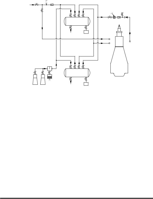
Fig. 13.01.01: Starting and control air system
The starting air of 30 bar is supplied by the starting air compressors (4 50 602) to the starting air receivers (4 50 615) and from these to the main engine inlet ‘A’.
Through a reducing station (4 50 665), compressed air at 7 bar is supplied to the control air for exhaust valve air springs, through ‘B’.
Through a reducing valve (4 50 675) is supplied compressed air at 10 bar to ‘AP’ for turbocharger cleaning (soft blast) , and a minor volume used for the fuel valve testing unit.
Starting air and control air for the GenSets can be supplied from the same starting air receivers, as for the main engine.
Please note that the air consumption for control air, safety air, turbocharger cleaning, sealing air for exhaust valve and for fuel valve testing unit are momentary requirements of the consumers.
For information about a common starting air system for main engines and MAN Diesel auxiliary engines, please refer to our publication:
Uni concept Auxiliary Systems for Two stroke Main
The publication is available at www.mandiesel.com under ‘Quicklinks’ → ‘Technical Papers’
MAN B&W S90ME C7, K90ME C6
MAN Diesel |
198 39 96 7.3 |
|

MAN B&W |
13.02 |
|
|
Components for Starting Air System
Starting air compressors
The starting air compressors are to be of the water cooled, two stage type with intercooling.
More than two compressors may be installed to supply the total capacity stated.
Air intake quantity: |
|
Reversible engine, |
|
for 12 starts ........................ |
see ‘List of capacities’ |
Non reversible engine, |
|
for 6 starts .......................... |
see ‘List of capacities’ |
Delivery pressure ......................................... |
30 bar |
Starting air receivers
The volume of the two receivers is:
Reversible engine, |
|
for 12 starts ...................... |
see ‘List of capacities’ * |
Non reversible engine, |
|
for 6 starts ........................ |
see ‘List of capacities’ * |
Working pressure ......................................... |
30 bar |
Test pressure .................... |
according to class rule |
* The volume stated is at 25 °C and 1,000 mbar
Reduction station for control and safety air
In normal operating, each of the two lines supplies one engine inlet. During maintenance, three isolating valves in the reduction station allow one of the two lines to be shut down while the other line supplies both engine inlets, see Fig. 13.01.01.
Reduction .......................... |
from 30 10 bar to 7 bar |
|
(Tolerance ±10%) |
Flow rate, free air .............. |
2,100 Normal liters/min |
|
equal to 0.035 m3/s |
Filter, fineness .............................................. |
40 µm |
Page of 1
Reduction valve for turbocharger cleaning etc
Reduction .......................... |
from 30 10 bar to 7 bar |
|
(Tolerance ±10%) |
Flow rate, free air ............. |
2,600 Normal liters/min |
|
equal to 0.043 m3/s |
The consumption of compressed air for control air, exhaust valve air springs and safety air as well as air for turbocharger cleaning and fuel valve testing is covered by the capacities stated for air receivers and compressors in the list of capacities.
Starting and control air pipes
The piping delivered with and fitted onto the main engine is shown in the following figures in Section 13.03:
Fig. 13.03.01 Starting air pipes
Fig. 13.03.02 Air spring pipes, exhaust valves
Turning gear
The turning wheel has cylindrical teeth and is fitted to the thrust shaft. The turning wheel is driven by a pinion on the terminal shaft of the turning gear, which is mounted on the bedplate.
Engagement and disengagement of the turning gear is effected by displacing the pinion and terminal shaft axially. To prevent the main engine from starting when the turning gear is engaged, the turning gear is equipped with a safety arrangement which interlocks with the starting air system.
The turning gear is driven by an electric motor with a built in gear and brake. Key specifications of the electric motor and brake are stated in Section 13.04.
MAN B&W ME/ME C/ME GI, S50ME-B8/9
MAN Diesel |
198 60 57 8.0 |
|
MAN B&W |
13.03 |
|
|
Page of 2
Starting and Control Air Pipes
:6æææ ç.æææ#
!CTIVATEæPILOTæPRESSURE
TOæSTARTINGæVALVES
#YL æ
3TARTINGæVALVE
"URSTINGæCAP
:3ææ ç!æææ)æææ#
:3æææ ç!ææ# 

:3æææ ç"ææ# |
|
"LOWæOFF |
"LOWæOFF |
:3ææ ç!æææ)æææ# |
:3ææ ç"æææ)æææ# 


 :3ææ ç!æææ)æææ#


 :3ææ ç"æææ)æææ#
:3ææ ç"æææ)æææ#
3LOWæTURNING |
æ æ |
04æææ ç!æææ)æææ!, |
04æææ ç"æææ)æææ!, |
!
|
0)æææ |
|
,OCALæOPERATINGæPANEL |
|
|||
|
|
|
|
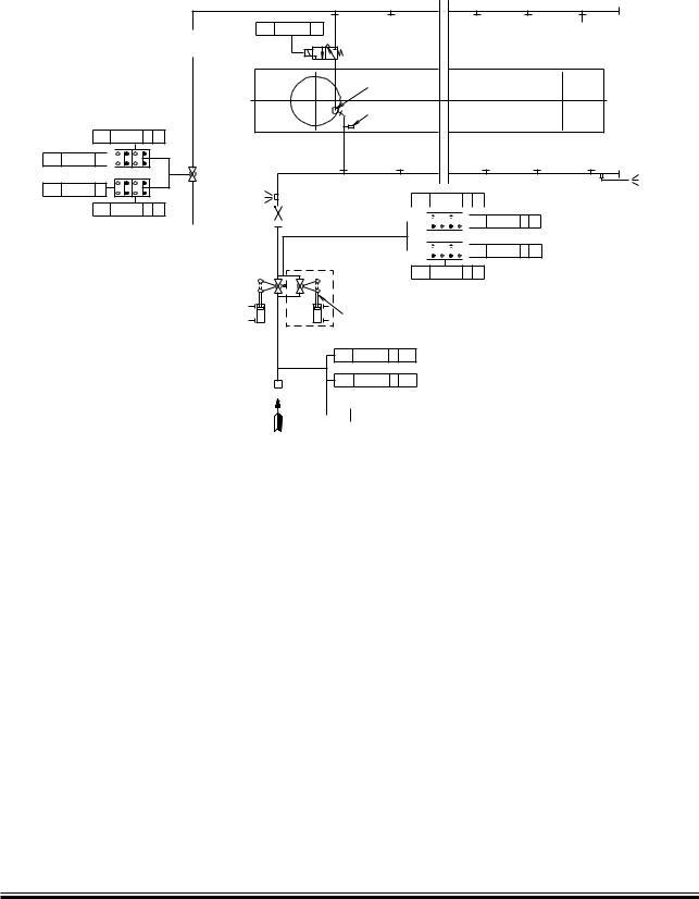
The letters refer to list of ‘Counterflanges’
The item Nos. refer to ‘Guidance values automation’ The piping is delivered with and fitted onto the engine
198 98 21 5.3
Fig. 13.03.01: Starting air pipes
The starting air pipes, Fig. 13.03.01, contain a main starting valve (a ball valve with actuator), a non return valve, a solenoid valve and a starting valve. The main starting valve is controlled by the Engine Control System. Slow turning before start of engine (4 50 140) is included in the basic design.
The Engine Control System regulates the supply of control air to the starting valves in accordance with the correct firing sequence and the timing.
Please note that the air consumption for control air, turbocharger cleaning and for fuel valve testing unit are momentary requirements of the consumers. The capacities stated for the air receivers
and compressors in the ‘List of Capacities’ cover all the main engine requirements and starting of the auxiliary engines.
For information about a common starting air system for main engines and auxiliary engines, please refer to the Engine Selection Guide or to our publication:
Uni concept Auxiliary Systems for Two stroke Main
The publication is available at www.mandiesel.com under ‘Quicklinks’ → ‘Technical Papers’
MAN B&W ME/ME C/ME GI engines
MAN Diesel |
198 40 00 4.5 |
|
MAN B&W |
13.03 |
|
|
|
Page of 2 |
Exhaust Valve Air Spring Pipes
The exhaust valve is opened hydraulically by the Fuel Injection Valve Actuator (FIVA) system which is activated by the Engine Control System, and the closing force is provided by an ‘air spring’ which leaves the valve spindle free to rotate.
The compressed air is taken from the control air supply, see Fig. 13.03.02.
04æææ ç!æææ)æææ!,æææ9 |
|
04æææ ç"æææ)æææ!,æææ9 |
|
" |
|
|
|
#ONTROLæAIRæSUPPLYæ FROM |
3AFETYæRELIEFæVALVE |
3AFETYæRELIEFæVALVE |
3AFETYæRELIEFæVALVE |
THEæPNEUMATICæSYSTEM |
|
|
|
|
!IR |
|
|
|
SPRING |
|
|
The item Nos. refer to ‘Guidance values automation’
The piping is delivered with and fitted onto the engine
121 36 87-1.1.0c
Fig. 13.03.02: Air spring pipes for exhaust valves
MAN B&W ME/ME C/ME GI engines
MAN Diesel |
198 40 00 4.5 |
|