Main Section 917 Engine room crane
Engine room crane capacity, overhauling space
Main Section 918 Torsiograph arrangement
Torsiograph arrangement
Main Section 919 Shaft earthing device
Earthing device
Main Section 920 Fire extinguishing in scavenge air space
Fire extinguishing in scavenge air space
Main Section 921 Instrumentation
Axial vibration monitor
Main Section 926 Engine seating
Profile of engine seating
Epoxy chocks
Alignment screws
Main Section 927 Holding down bolts
Holding down bolt Round nut Distance pipe Spherical washer Spherical nut
Assembly of holding down bolt Protecting cap
Arrangement of holding down bolts
Main Section 928 Supporting chocks
Supporting chocks
Securing of supporting chocks
Main Section 929 Side chocks
Side chocks
Liner for side chocks, starboard
Liner for side chocks, port side
Main Section 930 End chocks
Stud for end chock bolt
End chock
Round nut
Spherical washer, concave
Spherical washer, convex
Assembly of end chock bolt
Liner for end chock
Protecting cap
Page of 4
Main Section 931 Top bracing of engine
Top bracing outline
Top bracing arrangement Friction materials
Top bracing instructions Top bracing forces
Top bracing tension data
Main Section 932 Shaft line
Static thrust shaft load
Fitted bolt
Main Section 933 Power Take Off
List of capacities
PTO/RCF arrangement, if fitted
Main Section 936 Spare parts dimensions
Connecting rod studs Cooling jacket Crankpin bearing shell Crosshead bearing Cylinder cover stud Cylinder cover Cylinder liner Exhaust valve
Exhaust valve bottom piece Exhaust valve spindle Exhaust valve studs
Fuel valve
Main bearing shell Main bearing studs Piston complete Starting valve Telescope pipe Thrust block segment Turbocharger rotor
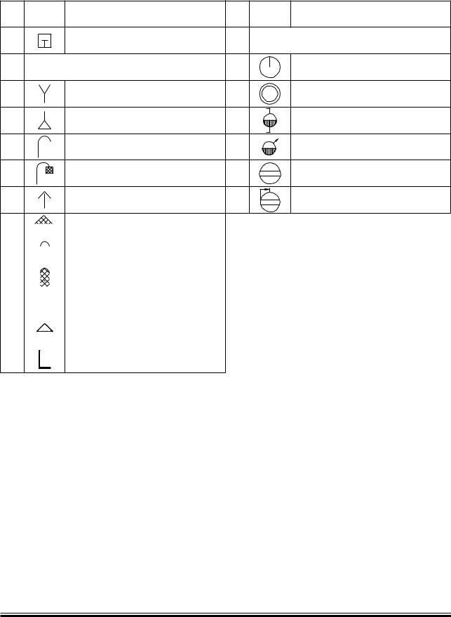
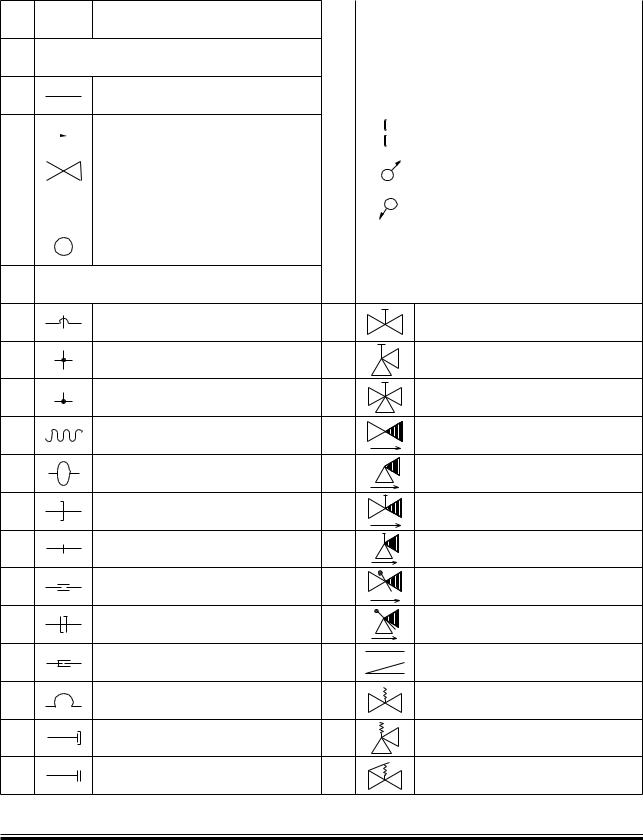
Main Section 940 Gaskets, sealings, O rings
Gaskets, sealings, O rings
Main Section 949 Material sheets
MAN B&W Standard Sheets Nos:
•S19R
•S45R
•S25Cr1
•S34Cr1R
•C4


 Reduction valve
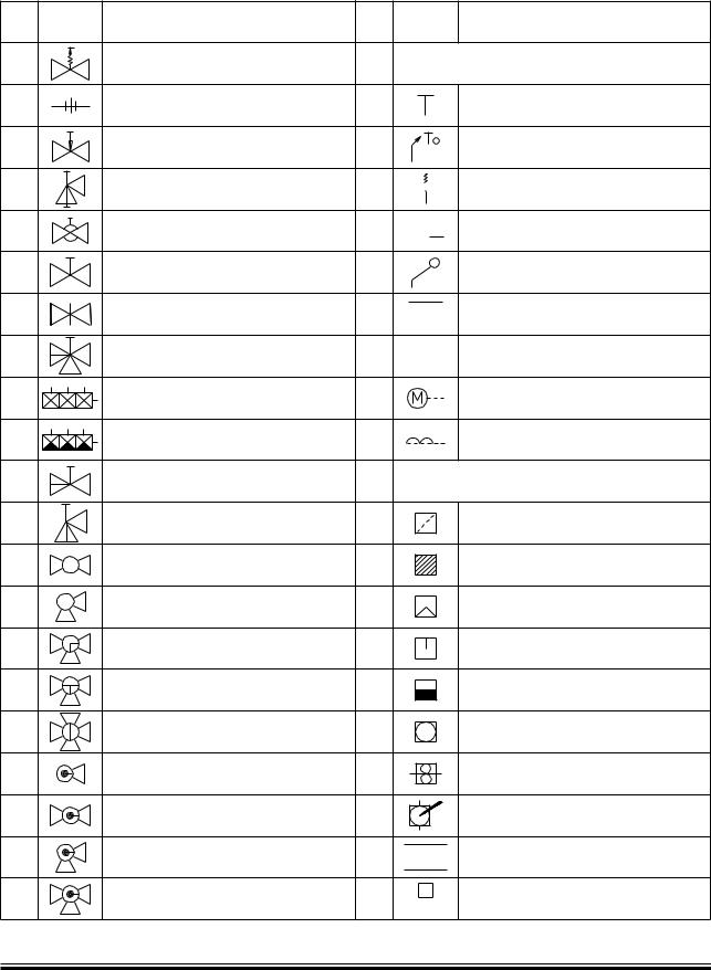
 Spring

 Mass
Mass

 Piston
 Membrane

 Ejector