

s90mec7
.pdfMAN B&W
Installation Aspects
5
MAN Diesel

MAN B&W |
5.01 |
|
|
|
Page of 1 |
Space requirements and overhaul heights
Space Requirements for the Engine
The space requirements stated in Section 5.02 are valid for engines rated at nominal MCR (L1).
The additional space needed for engines equipped with PTO is stated in Chapter 4.
If, during the project stage, the outer dimensions of the turbocharger seem to cause problems, it is possible, for the same number of cylinders, to use turbochargers with smaller dimensions by increasing the indicated number of turbochargers by one, see Chapter 3.
Overhaul of Engine
The distances stated from the centre of the crankshaft to the crane hook are for the normal lifting procedure and the reduced height lifting procedure (involving tilting of main components). The lifting capacity of a normal engine room crane can be found in Fig. 5.04.01.
The area covered by the engine room crane shall be wide enough to reach any heavy spare part required in the engine room.
A lower overhaul height is, however, available by using the MAN B&W Double Jib crane, built by Danish Crane Building A/S, shown in Figs. 5.04.02 and 5.04.03.
Please note that the distance ‘E’ in Fig. 5.02.01, given for a double jib crane is from the centre of the crankshaft to the lower edge of the deck beam.
A special crane beam for dismantling the turbocharger must be fitted. The lifting capacity of the crane beam for dismantling the turbocharger is stated in Section 5.03.
The overhaul tools for the engine are designed to be used with a crane hook according to DIN 15400, June 1990, material class M and load capacity 1Am and dimensions of the single hook type according to DIN 15401, part 1.
The total length of the engine at the crankshaft level may vary depending on the equipment to be fitted on the fore end of the engine, such as adjustable counterweights, tuning wheel, moment compensators or PTO.
Please note that the latest version of the dimensioned drawing is available for download at www.mandiesel.com under ‘Marine’ → ‘Low Speed’ → ‘Installation Drawings’. First choose engine series, then engine type and select ‘Outline drawing’ for the actual number of cylinders and type of turbocharger installation in the list of drawings available for download.
MAN B&W MC/MC C, ME/ME C/ME GI/ME-B engines
MAN Diesel |
198 43 75 4.5 |
|

MAN B&W |
5.02 |
|
|
|
Page of 1 |
Space Requirements
This section is available on request
MAN Diesel |
198 47 59-0.1 |
|
MAN B&W |
5.03 |
|
|
|
Page of 3 |
Crane beam for overhaul of turbocharger
|
a |
|
Crane beam for |
|
Crane beam for |
Crane beam |
transportation of |
|
components |
||
|
dismantling of |
||
|
|
|
|
|
components |
|
|
engine/aftMain cylinder |
|
Crane hook |
Engineroom side |
HB |
|
||
|
Gas outlet flange |
|
|
|
|
Turbocharger |
|
|
|
|
b |
178 52 34 0.1
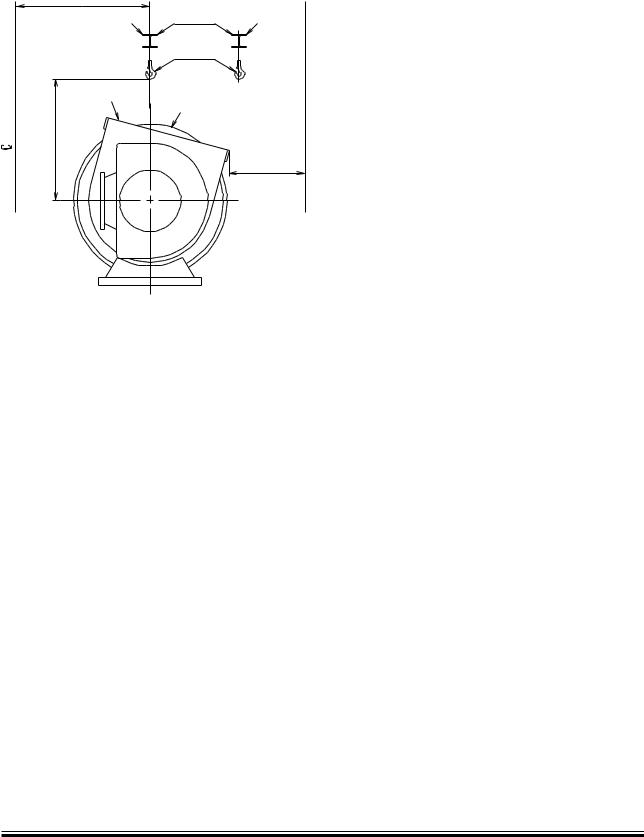
Fig. 5.03.01a: Required height and distance
For the overhaul of a turbocharger, a crane beam with trolleys is required at each end of the turbocharger.
Two trolleys are to be available at the compressor end and one trolley is needed at the gas inlet end.
Crane beam no. 1 is for dismantling of turbocharger components.
Crane beam no. 2 is for transporting turbocharger components.
See Figs. 5.03.01a and 5.03.02.
The crane beams can be omitted if the main engine room crane also covers the turbocharger area.
The crane beams are used and dimensioned for lifting the following components:
•Exhaust gas inlet casing
•Turbocharger inlet silencer
•Compressor casing
•Turbine rotor with bearings
MAN B&W |
|
|
|
|
|
Units |
TCA77 |
TCA88 |
|
|
|
|
|
|
W |
kg |
2,000 |
3,000 |
|
HB |
mm |
1,800 |
2,000 |
|
b |
m |
800 |
1,000 |
|
|
|
|
|
|
ABB |
|
|
|
|
|
Units |
TPL80 |
TPL85 |
|
|
|
|
|
|
W |
kg |
1,500 |
3,000 |
|
HB |
mm |
1,900 |
2,200 |
|
b |
m |
800 |
1,000 |
|
|
|
|
|
|
Mitsubishi |
|
|
|
|
|
Units |
MET71 |
MET83 |
MET90 |
|
|
|
|
|
W |
kg |
1,800 |
2,700 |
3,500 |
HB |
mm |
1,800 |
2,200 |
2,200 |
b |
m |
800 |
800 |
800 |
The figures ‘a’ are stated on the ‘Engine and Gallery Outline’ drawing, Section 5.06.
Fig. 5.03.01b: Required height and distance and weight
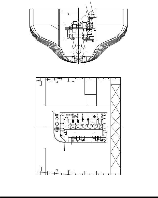
The crane beams are to be placed in relation to the turbocharger(s) so that the components around the gas outlet casing can be removed in connection with overhaul of the turbocharger(s).
The crane beam can be bolted to brackets that are fastened to the ship structure or to columns that are located on the top platform of the engine.
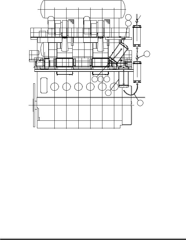
The lifting capacity of the crane beam for the heaviest component ‘W’, is indicated in Fig. 5.03.01b for the various turbocharger makes. The crane beam shall be dimensioned for lifting the weight ‘W’ with a deflection of some 5 mm only.
HB indicates the position of the crane hook in the vertical plane related to the centre of the turbocharger. HB and b also specifies the minimum space for dismantling.
For engines with the turbocharger(s) located on the exhaust side, EoD No. 4 59 122, the letter ‘a’ indicates the distance between vertical centrelines of the engine and the turbocharger.
MAN B&W S90MC-C/ME-C7/8, S80MC-C/ME-C7
MAN Diesel |
198 44 93-9.3 |
|
MAN B&W |
5.03 |
|
|
Crane beam for turbochargers
#RANEæBEAMæFORæTRANSPORTATIONæOFæCOMPONENTS |
#RANEæBEAMæFORæDISMANTLINGæOFæCOMPONENTS |
3PARES |
#RANEæBEAMæFORæDISMANTLINGæOFæCOMPONENTS |
#RANEæBEAMæFORæTRANSPORTATIONæOFæCOMPONENTS |
Fig. 5.03.02: Crane beam for turbocharger
Page of 3
178 52 74 6.0
MAN B&W 60MC C/ME C, S65ME C, 70MC C/ME C, S/K80MC C/ME C, 90MC/MC C/ME/ME C, 98MC/MC C/ME/ME C
MAN Diesel |
198 48 48 8.1 |
|
MAN B&W |
5.03 |
|
|
|
Page of 3 |
Crane beam for overhaul of air cooler
%NGINEæROOMæCRANE
æ
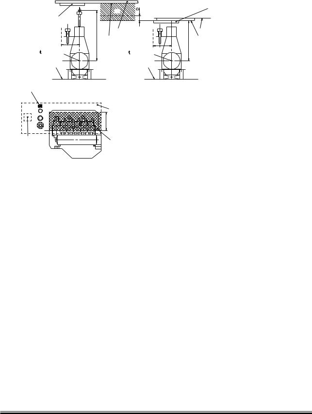
Fig.: 5.03.03: Crane beam for overhaul of air cooler
Overhaul/exchange of charge air cooler.
The text and figure are for guidance only.
Valid for air cooler design for the following engines with more than one turbochargers mounted on the exhaust side:
•60MC/MC C/ME C
•S65ME C
•70MC/MC C/ME C
•80MC/MC C/ME C
•90MC C/ME/ME C
•98MC/MC C/ME/ME C
1.Dismantle all the pipes in the area around the air cooler.
2.Dismantle all the pipes around the inlet cover for the cooler.
178 52 73 4.0
3.Take out the cooler insert by using the above placed crane beam mounted on the engine.
4.Turn the cooler insert to an upright position.
5.Dismantle the platforms below the air cooler.
6.Lower down the cooler insert between the gallery brackets and down to the engine room floor.
Make sure that the cooler insert is supported, e.g. on a wooden support.
7.Move the air cooler insert to an area covered by the engine room crane using the lifting beam mounted below the lower gallery of the engine.
8.By using the engine room crane the air cooler insert can be lifted out of the engine room.
MAN B&W 60MC/MC C/ME C, S65ME C, 70MC/MC C/ME C, 80MC/MC C/ME C, 90MC C/ME/ME C, 98MC/MC C/ME/ME C
MAN Diesel |
198 48 51 1.2 |
|
MAN B&W Diesel A/S |
5.04 |
|
|
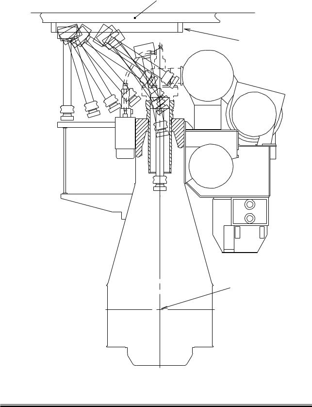
Engine room crane
Normal crane
A
Crankshaft
Base line
Spares
Engine room hatch
Fig. 5.04.01: Engine room crane
Page 1 of 3
|
2) |
D |
MAN B&W Double-Jib Crane |
|
|
|
|
||
|
|
|
|
|
|
Deck |
|
|
Deck |
1) |
Deck beam |
|
|
Deck beam |
B1/B2 |
|
|
||
|
|
A |
C |
|
Crankshaft
Base line
178 23 34-2.0
|
Recommended |
|
|
area to be covered |
|
A |
by the engine room |
|
crane |
||
|
||
|
Minimum area to |
|
|
be covered by the |
|
|
engine room crane |
1)The lifting tools for the engine are designed to fit together with a standard crane hook with a lifting capacity in accordance with the figure stated in the table. If a larger crane hook is used, it may not fit directly to the overhaul tools, and the use of an intermediate shackle or similar between the lifting tool and the crane hook will affect the requirements for the minimum lifting height in the engine room (dimension B)
2)The hatched area shows the height where an MAN B&W Double-Jib Crane has to be used.
Weight in kg including |
Crane capacity |
Crane |
Normal crane |
MAN B&W Double-Jib Crane |
|||||
lifting tools |
in tons selected in |
operating |
Height to crane hook |
|
|
||||
|
|
|
accordance with |
width |
in mm for: |
|
|
||
|
|
|
DIN and JIS stan- |
in mm |
|
|
|
|
|
|
|
|
Normal |
Reduced |
Building-in height |
||||
|
|
|
dard |
|
|||||
|
|
|
|
lifting |
height lifting |
in mm |
|||
|
|
|
capacities |
|
|||||
|
|
|
|
procedure |
procedure |
|
|
||
|
|
|
|
|
|
|
|
||
|
|
|
|
|
|
|
involving til- |
|
|
|
|
|
|
|
|
|
ting of main |
|
|
|
|
|
|
|
|
|
components |
|
|
|
|
|
|
|
|
|
(option) |
|
|
|
|
|
|
|
|
|
|
|
|
Cylinder |
Cylinder |
Piston |
Normal |
MAN |
A |
B1 |
B1 |
C |
D |
cover |
liner |
with |
crane |
B&W |
Minimum |
Minimum |
Minimum |
Minimum height |
Additional height |
complete |
with |
piston |
|
Double- |
distance |
height from |
height from |
from centreline |
required for |
with |
cooling |
rod and |
|
Jib |
|
centreline |
centreline |
crankshaft to |
removal of |
exhaust |
jacket |
stuffing |
|
Crane |
|
crankshaft |
crankshaft to |
underside deck |
exhaust valve |
valve |
|
box |
|
|
|
to |
underside |
beam |
without removing |
|
|
|
|
|
|
centreline |
deck beam |
|
any exhaust |
|
|
|
|
|
|
crane hook |
|
|
valve stud |
|
|
|
|
|
|
|
|
|
|
9,200 |
9,175 |
5,325 |
10.0 |
2x6.3 |
3,900 |
14,500 |
13,525 |
14,275 |
500 |
|
|
|
|
|
|
|
|
|
|
The crane hook travelling area must cover at least the full length of the engine and a width in accordance with dimension A given on the drawing, see cross-hatched area.
It is furthermore recommended that the engine room crane can be used for transport of heavy spare parts from the engine room hatch to the spare part stores and to the engine. See example on this drawing.
The crane hook should at least be able to reach down to a level corresponding to the centreline of the crankshaft.
For overhaul of the turbocharger(s), trolley mounted chain hoists must be installed on a separate crane beam or, alternatively, in combination with the engine room crane structure, see ‘Crane beam for overhaul of turbochargers’ with information about the required lifting capacity for overhaul of turbocharger(s).
S90ME-C |
198 45 03-7.1 |
MAN B&W |
5.04 |
|
|
Page of 3
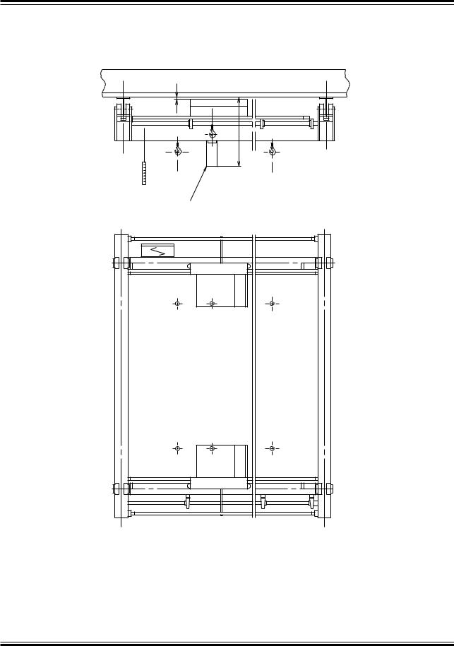
Overhaul with MAN B&W Double Jib crane
Deck beam
MAN B&W Double-Jib Crane
The Double Jib crane is available from:
Centreline crankshaft
Danish Crane Building A/S P.O. Box 54
Østerlandsvej 2 DK 9240 Nibe, Denmark
Telephone:+ 45 98 35 31 33
Telefax: + 45 98 35 30 33 E mail: dcb@dcb.dk
178 24 86 3.0
Fig. 5.04.02: Overhaul with Double Jib crane
MAN B&W MC/MC C, ME-B/ME/ME C/ME GI engines
MAN Diesel |
198 45 34 8.2 |
|
MAN B&W
MAN B&W Double Jib Crane
$ECKæBEAM |
|
- |
#HAINæCOLLECTINGæBOX |
This crane is adapted to the special tool for low overhaul.
Dimensions are available on request.
Fig. 5.04.03: MAN B&W Double Jib crane, option: 4 88 701
5.04
Page of 3
178 37 30-1.0
MAN B&W MC/MC C, ME/ME C/ ME-GI/ME-B engines
MAN Diesel |
198 45 41 9.1 |
|