

s90mec7
.pdfMAN B&W |
|
|
|
4.05 |
|
|
|
Page |
of 8 |
|
|
|
-AINTENANCEæSPACE |
|
|
æçæ æM |
|
æçæ æM |
|
|
2EDUCTIONæGEAR |
|
|
|
0OWERæTURBINE |
3TEAMæTURBINE |
2EDUCTIONæGEAR |
'ENERATOR |
|
|
|
|
/VERHAULжHEIGHT жMжзжжжж |
|
%XPANSIONæJOINT |
|
#ONDENSER |
|
|
|
|
|
æMæçæ |
|
|
|
|
#ONDENSATEæPUMP |
|
|
æçæ æM |
|
-AINTENANCEæSPACE |
|
|
|
æçæ æM |
|
|
|
|
|
7IDTH æ çæ æM |
|
|
|
|
178 57 06-2.0 |
|
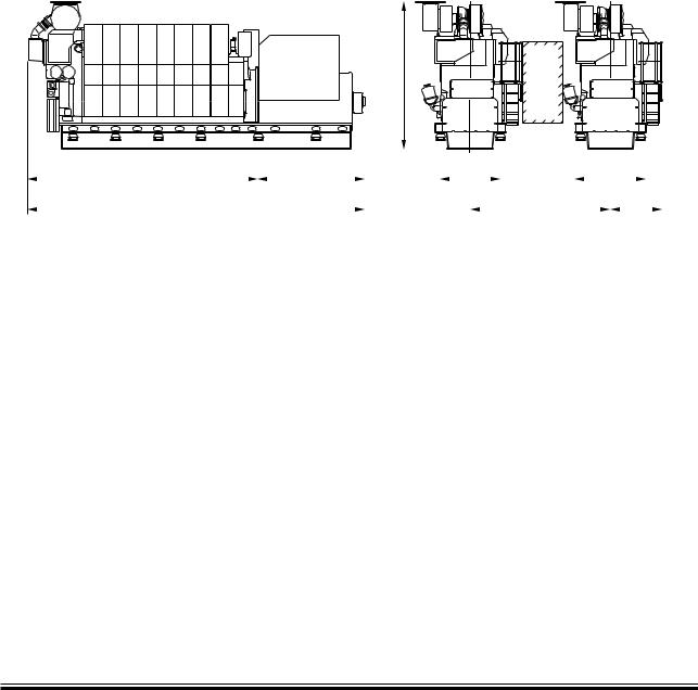
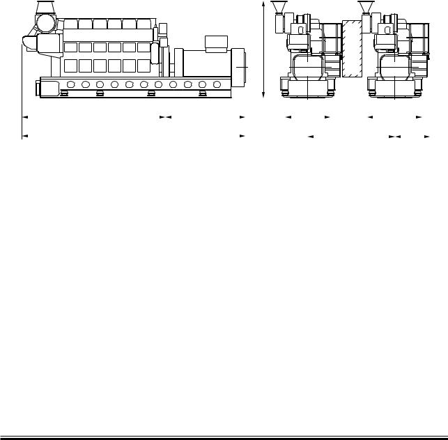
Fig. 4.05.06: Typical system size for 4,000 kW combined turbines
MAN B&W S90MC-C/ME-C7/8, K90ME9, K90MC-C/ME-C6
MAN Diesel |
198 57 98-9.2 |
|

MAN B&W |
4.05 |
|
|
|
Page of 8 |
WHR output
Because all the components come from different manufacturers, the final output and the system efficiency has to be calculated from case to case. However, Fig. 4.05.07 shows a guidance of possible outputs based on theoretically calculated outputs from the system.
Detailed information on the different systems is found in our paper ‘Thermo Efficiency System’, where the different systems are described in greater detail. The paper is available at: www. mandiesel.com under ‘Quicklinks’ → ‘Technical Papers’, from where it can be downloaded.
Guidance output of WHR for S90MC-C/ME-C7 engine rated in L1 at ISO conditions
Cyl. |
Engine power |
PTG |
STG |
Combined Turbines |
|
|
|
|
|
||
% SMCR |
kWe |
kWe |
kWe |
||
|
|||||
|
|
|
|
|
|
6 |
100 |
1,152 |
1,665 |
2,592 |
|
|
|
|
|
||
80 |
729 |
1,179 |
1,728 |
||
|
|||||
|
|
|
|
|
|
7 |
100 |
1,341 |
1,953 |
3,033 |
|
|
|
|
|
||
80 |
855 |
1,377 |
2,025 |
||
|
|||||
|
|
|
|
|
|
8 |
100 |
1,539 |
2,250 |
3,483 |
|
|
|
|
|
||
80 |
981 |
1,593 |
2,322 |
||
|
|||||
|
|
|
|
|
|
9 |
100 |
1,737 |
2,529 |
3,924 |
|
|
|
|
|
||
80 |
1,107 |
1,791 |
2,619 |
||
|
|||||
|
|
|
|
|
Table 4.05.07: Theoretically calculated outputs
MAN B&W S90MC-C/ME-C7
MAN Diesel |
198 58 05-1.2 |
|

MAN B&W |
4.06-8 |
|
|
|
Page of 1 |
GenSet Data
This section is not applicable
MAN Diesel |
198 47 92 3.0 |
|
MAN Diesel |
|
|
|
|
|
4.09 |
||
|
|
|
|
|
|
|
|
|
|
|
|
|
|
|
|
|
Page of 3 |
L27/38 GenSet Data |
|
|
|
|
|
|
|
|
|
|
Bore: 270 mm |
|
|
|
|
Stroke: 380 mm |
|
|
|
|
|
|
|
|
|
|
|
|
|
Power layout |
|
|
|||
|
|
|
|
|
|
|
|
|
|
|
720 r/min |
60 Hz |
|
|
750 r/min |
50 Hz |
|
|
|
Eng. kW |
Gen. kW |
|
|
Eng. kW |
Gen. kW |
|
|
|
|
|
|
|
|
|
|
|
5L27/38 |
1,500 |
1,440 |
1,600 |
1,536 |
|
||
|
|
|
|
|
|
|
|
|
|
6L27/38 |
1,980 |
1,900 |
1,980 |
1,900 |
|
||
|
|
|
|
|
|
|
|
|
|
7L27/38 |
2,310 |
2,218 |
2,310 |
2,218 |
|
||
|
|
|
|
|
|
|
|
|
|
8L27/38 |
2,640 |
2,534 |
2,640 |
2,534 |
|
||
|
|
|
|
|
|
|
|
|
|
9L27/38 |
2,970 |
2,851 |
2,970 |
2,851 |
|
||
|
|
|
|
|
|
|
|
|
|
|
|
|
|
|
|
|
|
H |
P |
|
|
|
|
|
|
|
|
|
|
|
|
|
|
|
|
|
|
|
|
|
|
|
|
|
|
|
|
|
|
|
|
|
|
|
|
|
|
|
|
|
|
|
|
|
|
|
|
|
|
|
|
|
|
|
|
|
|
|
|
|
|
|
|
|
|
|
|
|
|
|
|
|
|
|
|
|
|
|
|
|
|
|
|
A |
|
|
|
|
|
B |
|
|
|
|
|
,480 |
|
|
|
|
,770 |
|
|
|
|
||||||||||||
|
|
|
|
|
|
|
|
|
|
|
|
|
|
|
|
|
|
|
|
|
|
|
||||||||||||||||
|
|
|
|
|
|
|
|
|
|
|
|
|
|
|
|
|
|
|
|
|
|
|
||||||||||||||||
|
|
|
|
|
|
|
|
|
|
|
|
|
|
|
|
|
|
|
|
|
|
|
||||||||||||||||
|
|
|
|
|
|
|
|
|
|
|
|
|
|
|
|
|
|
|
|
|
|
|
|
|
|
|
|
|
|
|
|
|
|
|
|
|
|
|
|
|
|
|
|
|
|
|
|
C |
|
|
|
|
|
|
|
|
|
|
Q |
|
,285 |
|
|
||||||||||||||
|
|
|
|
|
|
|
|
|
|
|
|
|
|
|
|
|
|
|
|
|
|
|
|
|
|
|
|
|
|
|
|
|
|
|
|
|
|
|
|
|
|
|
|
|
|
|
|
|
|
|
|
|
|
|
|
|
|
|
|
|
|
|
|
|
|
|
|
|
|
|
|
|
|
|
178 23 07 9.0 |
||
|
|
|
|
|
|
|
|
|
|
|
|
|
|
|
|
|
|
|
|
|
|
|
|
|
|
|
|
|
|
|
|
|
|
|
|
|
|
|
|
No. of Cyls. |
|
|
|
A (mm) |
|
|
|
|
|
* B (mm) |
|
|
* C (mm) |
|
|
|
|
|
H (mm) |
|
**Dry weight |
||||||||||||||||
|
|
|
|
|
|
|
|
|
|
|
|
|
|
|
|
|
GenSet (t) |
|||||||||||||||||||||
|
|
|
|
|
|
|
|
|
|
|
|
|
|
|
|
|
|
|
|
|
|
|
|
|
|
|
|
|
|
|
|
|||||||
|
|
|
|
|
|
|
|
|
|
|
|
|
|
|
|
|
|
|
|
|
|
|
|
|
|
|
|
|
|
|
|
|
|
|
|
|
|
|
5 |
(720 r/min) |
4,346 |
|
2,486 |
|
|
|
6,832 |
|
|
3,705 |
|
|
42.3 |
|
|
||||||||||||||||||||||
5 |
(750 r/min) |
4,346 |
|
2,486 |
|
|
|
6,832 |
|
|
3,705 |
|
|
42.3 |
|
|
||||||||||||||||||||||
|
|
|
|
|
|
|
|
|
|
|
|
|
|
|
|
|
|
|
|
|
|
|
|
|
|
|
|
|
|
|
|
|
|
|
|
|
|
|
6 |
(720 r/min) |
4,791 |
|
2,766 |
|
|
|
7,557 |
|
|
3,705 |
|
|
45.8 |
|
|
||||||||||||||||||||||
6 |
(750 r/min) |
4,791 |
|
2,766 |
|
|
|
7,557 |
|
|
3,717 |
|
|
46.1 |
|
|
||||||||||||||||||||||
|
|
|
|
|
|
|
|
|
|
|
|
|
|
|
|
|
|
|
|
|
|
|
|
|
|
|
|
|
|
|
|
|
|
|
|
|
|
|
7 |
(720 r/min) |
5,236 |
|
2,766 |
|
|
|
8,002 |
|
|
3,717 |
|
|
52.1 |
|
|
||||||||||||||||||||||
7 |
(750 r/min) |
5,236 |
|
2,766 |
|
|
|
8,002 |
|
|
3,717 |
|
|
52.1 |
|
|
||||||||||||||||||||||
|
|
|
|
|
|
|
|
|
|
|
|
|
|
|
|
|
|
|
|
|
|
|
|
|
|
|
|
|
|
|
|
|
|
|
|
|
|
|
8 |
(720 r/min) |
5,681 |
|
2,986 |
|
|
|
8,667 |
|
|
3,717 |
|
|
56.3 |
|
|
||||||||||||||||||||||
8 |
(750 r/min) |
5,681 |
|
2,986 |
|
|
|
8,667 |
|
|
3,717 |
|
|
58.3 |
|
|
||||||||||||||||||||||
|
|
|
|
|
|
|
|
|
|
|
|
|
|
|
|
|
|
|
|
|
|
|
|
|
|
|
|
|
|
|
|
|
|
|
|
|
|
|
9 |
(720 r/min) |
6,126 |
|
2,986 |
|
|
|
9,112 |
|
|
3,797 |
|
|
63.9 |
|
|
||||||||||||||||||||||
9 |
(750 r/min) |
6,126 |
|
2,986 |
|
|
|
9,112 |
|
|
3,797 |
|
|
63.9 |
|
|
||||||||||||||||||||||
|
|
|
|
|
|
|
|
|
|
|
|
|
|
|
|
|
|
|
|
|
|
|
|
|
|
|
|
|
|
|
|
|
|
|
|
|
||
P Free passage between the engines, width 600 mm and height 2,000 mm |
|
|
|
|
|
|
|
|
|
|
|
|
|
178 33 89 8.2 |
||||||||||||||||||||||||
QMin. distance between engines: 2,900 mm (without gallery) and 3,100 mm (with gallery) * Depending on alternator
**Weight includes a standard alternator
All dimensions and masses are approximate and subject to change without prior notice.
Fig. 4.09.01: Power and outline of L27/38
MAN B&W 98 → 50 MC/MC C, 108 → 50 ME/ME C, 70 → 60 ME GI, 50 → 35 ME B
MAN Diesel |
198 42 09 1.4 |
|

MAN Diesel |
4.09 |
|
|
Page |
of 3 |
L27/38 GenSet Data
|
|
Cyl. |
5 |
6 |
7 |
8 |
9 |
|
|
|
|
|
|
|
|
Max continues rating |
720 RPM |
kW |
1,500 |
1,980 |
2,310 |
2,640 |
2,970 |
Engine driven pumps: |
|
|
|
|
|
|
|
LT cooling water pump |
(2.5 bar) |
m³/h |
58 |
58 |
58 |
58 |
58 |
HT cooling water pump |
(2.5 bar) |
m³/h |
58 |
58 |
58 |
58 |
58 |
Lubricating oil main pump |
(8 bar) |
m³/h |
64 |
64 |
92 |
92 |
92 |
Separate pumps: |
|
|
|
|
|
|
|
Max. Delivery pressure of cooling water pumps |
bar |
2.5 |
2.5 |
2.5 |
2.5 |
2.5 |
|
Diesel oil pump |
(5 bar at fuel oil inlet A1) |
m³/h |
1.02 |
1.33 |
1.55 |
1.77 |
2.00 |
Fuel oil Supply pump |
(4 bar at discharge pressure) |
m³/h |
0.50 |
0.66 |
0.76 |
0.87 |
0.98 |
Fuel oil circulating pump |
(8 bar at fuel oil inlet A1) |
m³/h |
1.03 |
1.35 |
1.57 |
1.80 |
2.02 |
Cooling capacity: |
|
|
|
|
|
|
|
Lubricating oil |
|
kW |
206 |
283 |
328 |
376 |
420 |
Charge air LT |
|
kW |
144 |
392 |
436 |
473 |
504 |
Total LT system |
|
kW |
350 |
675 |
764 |
849 |
924 |
Flow LT at 36°C inlet and 44°C outlet |
m³/h |
38 |
58 |
58 |
58 |
58 |
|
Jacket cooling |
|
kW |
287 |
486 |
573 |
664 |
754 |
Charge air HT |
|
kW |
390 |
558 |
640 |
722 |
802 |
Total HT system |
|
kW |
677 |
1,044 |
1,213 |
1,386 |
1,556 |
Flow HT at 44°Cinlet and 80°C outlet |
m³/h |
16 |
22 |
27 |
32 |
38 |
|
Total from engine |
|
kW |
1,027 |
1,719 |
1,977 |
2,235 |
2,480 |
LT flow at 36°C inlet |
|
m³/h |
38 |
58 |
58 |
58 |
58 |
LT temp. Outlet engine |
|
°C |
59 |
58 |
61 |
64 |
68 |
(at 36°C and 1 string cooling water system) |
|
|
|
|
|
|
|
Gas Data: |
|
|
|
|
|
|
|
Exhaust gas flow |
|
kg/h |
10,476 |
15,000 |
17,400 |
19,900 |
22,400 |
Exhaust gas temp. |
|
°C |
330 |
295 |
295 |
295 |
295 |
Max. Allowable back press. |
|
bar |
0,025 |
0,025 |
0,025 |
0,025 |
0,025 |
Air consumption |
|
kg/h |
10,177 |
14,600 |
17,000 |
19,400 |
21,800 |
Starting Air System: |
|
|
|
|
|
|
|
Air consumption per start |
|
Nm3 |
2,5 |
2,9 |
3,3 |
3,8 |
4,3 |
Heat Radiation: |
|
|
|
|
|
|
|
Engine |
|
kW |
53 |
64 |
75 |
68 |
73 |
Alternator |
|
kW |
(see separate data from the alternator maker) |
||||
The stated heat balances are based on tropical conditions. The exhaust gas data (exhaust gas flow, exhaust gas temp. and air consumption). are based on ISO ambient condition.
* The outlet temperature of the HT water is fixed to 80°C, and 44°C for the LT water
At different inlet temperature the flow will change accordingly.
178 48 63 6.1
Example: If the inlet temperature is 25°C then the LT flow will change to (46-36)/(46-25)*100 = 53% of the original flow. The HT flow will not change.
Fig. 4.09.02a: List of capacities for L27/38, 720 rpm
MAN B&W 98 → 50 MC/MC C, 108 → 50 ME/ME C, 70 → 60 ME GI, 50 → 35 ME B
MAN Diesel |
198 42 09 1.4 |
|
MAN Diesel |
4.09 |
|
|
Page |
of 3 |
L27/38 GenSet Data
|
|
Cyl. |
5 |
6 |
7 |
8 |
9 |
|
|
|
|
|
|
|
|
Max continues rating |
750 RPM |
kW |
1,600 |
1,980 |
2,310 |
2,640 |
2,970 |
Engine driven pumps: |
|
|
|
|
|
|
|
LT cooling water pump |
2.5 bar |
m³/h |
70 |
70 |
70 |
70 |
70 |
HT cooling water pump |
2.5 bar |
m³/h |
70 |
70 |
70 |
70 |
70 |
Lubricating oil main pump |
8 bar |
m³/h |
66 |
66 |
96 |
96 |
96 |
Separate pumps: |
|
|
|
|
|
|
|
Max. Delivery pressure of cooling water pumps |
bar |
2.5 |
2.5 |
2.5 |
2.5 |
2.5 |
|
Diesel oil pump |
(5 bar at fuel oil inlet A1) |
m³/h |
1.10 |
1.34 |
1.57 |
1.79 |
2.01 |
Fuel oil supply pump |
(4 bar discharge pressure) |
m³/h |
0.54 |
0.66 |
0.77 |
0.88 |
0.99 |
Fuel oil circulating pump |
(8 bar at fuel oil inlet A1) |
m³/h |
1.11 |
1.36 |
1.59 |
1.81 |
2.04 |
Cooling capacity: |
|
|
|
|
|
|
|
Lubricating oil |
|
kW |
217 |
283 |
328 |
376 |
420 |
Charge air LT |
|
kW |
155 |
392 |
436 |
473 |
504 |
Total LT system |
|
kW |
372 |
675 |
764 |
849 |
924 |
Flow LT at 36°C inlet and 44°C outlet |
m³/h |
40 |
70 |
70 |
70 |
70 |
|
Jacket cooling |
|
kW |
402 |
486 |
573 |
664 |
754 |
Charge air HT |
|
kW |
457 |
558 |
640 |
722 |
802 |
Total HT system |
|
kW |
859 |
1,044 |
1,213 |
1,386 |
1,556 |
Flow HT at 44°Cinlet and 80°C outlet |
m³/h |
21 |
22 |
27 |
32 |
38 |
|
Total from engine |
|
kW |
1,231 |
1,719 |
1,977 |
2,235 |
2,480 |
LT flow at 36°C inlet |
|
m³/h |
40 |
70 |
70 |
70 |
70 |
LT temp. Outlet engine |
|
°C |
62 |
55 |
58 |
61 |
64 |
(at 36°C and 1 string cooling water system) |
|
|
|
|
|
|
|
Gas Data: |
|
|
|
|
|
|
|
Exhaust gas flow |
|
kg/h |
11,693 |
15,000 |
17,400 |
19,900 |
22,400 |
Exhaust gas temp. |
|
°C |
330 |
305 |
305 |
305 |
305 |
Max. Allowable back press. |
|
bar |
0.025 |
0.025 |
0.025 |
0.025 |
0.025 |
Air consumption |
|
kg/h |
11,662 |
14,600 |
17,000 |
19,400 |
21,800 |
Starting Air System: |
|
|
|
|
|
|
|
Air consumption per start |
|
Nm3 |
2.5 |
2.9 |
3.3 |
3.8 |
4.3 |
Heat Radiation: |
|
|
|
|
|
|
|
Engine |
|
kW |
54 |
64 |
75 |
68 |
73 |
Alternator |
|
kW |
(see separate data from the alternator maker) |
||||
The stated heat balances are based on tropical conditions. The exhaust gas data (exhaust gas flow, exhaust gas temp. and air consumption). are based on ISO ambient condition.
* The outlet temperature of the HT water is fixed to 80°C, and 44°C for the LT water
At different inlet temperature the flow will change accordingly.
178 48 63 6.1
Example: If the inlet temperature is 25°C then the LT flow will change to (46-36)/(46-25)*100 = 53% of the original flow. The HT flow will not change.
Fig. 4.09.02b: List of capacities for L27/38, 750 rpm
MAN B&W 98 → 50 MC/MC C, 108 → 50 ME/ME C, 70 → 60 ME GI, 50 → 35 ME B
MAN Diesel |
198 42 09 1.4 |
|
MAN Diesel |
|
|
|
|
|
4.10 |
||
|
|
|
|
|
|
|
|
|
|
|
|
|
|
|
|
|
Page of 2 |
L28/32H GenSet Data |
|
|
|
|
|
|
||
|
|
Bore: 280 mm |
|
|
|
|
Stroke: 320 mm |
|
|
|
|
|
|
|
|
|
|
|
|
|
Power layout |
|
|
|||
|
|
|
|
|
|
|
|
|
|
|
720 r/min |
60 Hz |
|
750 r/min |
50 Hz |
|
|
|
|
Eng. kW |
Gen. kW |
|
Eng. kW |
Gen. kW |
|
|
|
5L28/32H |
1,050 |
1,000 |
|
1,100 |
1,045 |
|
|
|
|
|
|
|
|
|
|
|
|
6L28/32H |
1,260 |
1,200 |
|
1,320 |
1,255 |
|
|
|
|
|
|
|
|
|
|
|
|
7L28/32H |
1,470 |
1,400 |
|
1,540 |
1,465 |
|
|
|
|
|
|
|
|
|
|
|
|
8L28/32H |
1,680 |
1,600 |
|
1,760 |
1,670 |
|
|
|
|
|
|
|
|
|
|
|
|
9L28/32H |
1,890 |
1,800 |
|
1,980 |
1,880 |
|
|
|
|
|
|
|
|
|
|
|
|
|
|
|
|
|
|
|
|
H |
P |
|
|
|
|
|
|
|
|
|
|
|
|
|
|
|
|
|
|
|
|
|
|
|
|
|
|
|
|
|
|
|
|
|
|
|
|
|
|
|
|
|
|
|
|
|
|
|
|
|
|
|
|
|
|
|
|
|
|
|
|
|
|
|
|
|
|
|
|
|
A |
|
|
|
|
|
|
|
|
|
B |
|
|
|
|
,490 |
|
|
|
,800 |
|
|
|
|
|||||||||
|
|
|
|
|
|
|
|
|
|
|
|
|
|
|
|
|
|
|
|||||||||||||||
|
|
|
|
|
|
|
|
|
|
|
|
|
|
|
|
|
|
|
|||||||||||||||
|
|
|
|
|
|
|
|
|
|
|
|
|
|
|
|
|
|
||||||||||||||||
|
|
|
|
|
|
|
|
|
|
|
|
|
|
|
|
|
|
|
|
|
|
|
|
|
|
|
|
, 26 |
|
|
|
||
|
|
|
|
|
C |
|
|
|
|
|
|
|
|
Q |
|
|
|
|
|||||||||||||||
|
|
|
|
|
|
|
|
|
|
|
|
|
|
|
|
|
|
|
|
|
|
|
|
|
|
|
|
|
|
|
|
|
|
|
|
|
|
|
|
|
|
|
|
|
|
|
|
|
|
|
|
|
|
|
|
|
|
|
|
|
|
|
|
178 23 09 2.0 |
|||
|
No. of Cyls. |
A (mm) |
* B (mm) |
* C (mm) |
H (mm) |
**Dry weight |
|
|
|
GenSet (t) |
|||||
|
|
|
|
|
|
||
5 |
(720 r/min) |
4,279 |
2,400 |
6,679 |
3,184 |
|
32.6 |
5 |
(750 r/min) |
4,279 |
2,400 |
6,679 |
3,184 |
|
32.6 |
|
|
|
|
|
|
|
|
6 |
(720 r/min) |
4,759 |
2,510 |
7,269 |
3,184 |
|
36.3 |
6 |
(750 r/min) |
4,759 |
2,510 |
7,269 |
3,184 |
|
36.3 |
|
|
|
|
|
|
|
|
7 |
(720 r/min) |
5,499 |
2,680 |
8,179 |
3,374 |
|
39.4 |
7 |
(750 r/min) |
5,499 |
2,680 |
8,179 |
3,374 |
|
39.4 |
|
|
|
|
|
|
|
|
8 |
(720 r/min) |
5,979 |
2,770 |
8,749 |
3,374 |
|
40.7 |
8 |
(750 r/min) |
5,979 |
2,770 |
8,749 |
3,374 |
|
40.7 |
|
|
|
|
|
|
|
|
9 |
(720 r/min) |
6,199 |
2,690 |
8,889 |
3,534 |
|
47.1 |
9 |
(750 r/min) |
6,199 |
2,690 |
8,889 |
3,534 |
|
47.1 |
|
|
|
|
|
|
|
|
P Free passage between the engines, width 600 mm and height 2,000 mm
Q Min. distance between engines: 2,655 mm (without gallery) and 2,850 mm (with gallery)
*Depending on alternator
** Weight includes a standard alternator, make A. van Kaick
178 33 92 1.3
Fig. 4.10.01: Power and outline of L28/32H
MAN B&W 98 → 50 MC/MC C, 108 → 50 ME/ME C, 70 → 60 ME GI, 50 → 35 ME B
MAN Diesel |
198 42 10 1.4 |
|

MAN Diesel |
|
|
|
|
|
|
|
4.10 |
|
|
|
|
|
|
|
|
|
|
|
|
|
|
|
|
Page of 2 |
|
L28/32H GenSet Data |
|
|
|
|
|
|
|
|
|
|
|
|
|
|
|
|
|
|
|
Cyl. |
5-ECR |
5 |
6 |
7 |
8 |
9 |
|
|
|
|
|
|
|
|
|
Max. continuous rating at |
720/ |
kW |
875/ |
1,050/ |
1,260/ |
1,470/ |
1,680/ |
1,890/ |
750 RPM |
925 |
1,100 |
1,320 |
1,540 |
1,760 |
1,980 |
||
Engine-driven Pumps: |
|
|
|
|
|
|
|
|
Fuel oil feed pump |
(5.5-7.5 bar) |
m3/h |
1.4 |
1.4 |
1.4 |
1.4 |
1.4 |
1.4 |
L.T. cooling water pump |
(1-2.5 bar) |
m3/h |
45 |
45 |
60 |
75 |
75 |
75 |
H.T. cooling water pump |
(1-2.5 bar) |
m3/h |
45 |
45 |
45 |
60 |
60 |
60 |
Lub. oil main pump |
(3-5 bar) |
m3/h |
23 |
23 |
23 |
31 |
31 |
31 |
Separate Pumps: |
|
|
|
|
|
|
|
|
Diesel oil Pump |
(4 bar at fuel oil inlet A1) |
m³/h |
0.60/0.64 |
0.73/0.77 0.88/0.92 1.02/1.08 1.17/1.23 1.32/1.38 |
||||
Fuel oil supply pump *** |
(4 bar discharge pressure) |
m3/h |
0.29/0.31 |
0.36/0.38 0.43/0.45 0.50/0.53 0.57/0.60 0.64/0.68 |
||||
Fuel oil circulating pump |
(8 bar at fuel oil inlet A1) |
m³/h |
0.61/0.65 |
0.74/0.78 |
0.89/0.93 |
1.04/1.09 |
1.18/1.25 |
1.33/1.40 |
L.T. cooling water pump* |
(1-2.5 bar) |
m3/h |
45 |
45 |
54 |
65 |
77 |
89 |
L.T. cooling water pump** |
(1-2.5 bar) |
m3/h |
65 |
65 |
73 |
95 |
105 |
115 |
H.T. cooling water pump |
(1-2.5 bar) |
m3/h |
37 |
37 |
45 |
50 |
55 |
60 |
Lub. oil stand-by pump |
(3-5 bar) |
m3/h |
22 |
22 |
23 |
25 |
27 |
28 |
Cooling Capacities: |
|
|
|
|
|
|
|
|
Lubricating Oil: |
|
|
|
|
|
|
|
|
Heat dissipation |
|
kW |
91 |
105 |
127 |
149 |
172 |
194 |
L.T. cooling water quantity* |
|
m3/h |
6.4 |
7.8 |
9.4 |
11.0 |
12.7 |
14.4 |
SW L.T. cooling water quantity** |
m3/h |
28 |
28 |
28 |
40 |
40 |
40 |
|
Lub. oil temp. inlet cooler |
|
°C |
67 |
67 |
67 |
67 |
67 |
67 |
L.T. cooling water temp. inlet cooler |
°C |
36 |
36 |
36 |
36 |
36 |
36 |
|
Charge Air: |
|
|
|
|
|
|
|
|
Heat dissipation |
|
kW |
305 |
393 |
467 |
541 |
614 |
687 |
L.T. cooling water quantity |
|
m3/h |
37 |
37 |
45 |
55 |
65 |
75 |
L.T. cooling water inlet cooler |
°C |
36 |
36 |
36 |
36 |
36 |
36 |
|
Jacket Cooling: |
|
|
|
|
|
|
|
|
Heat dissipation |
|
kW |
211 |
264 |
320 |
375 |
432 |
489 |
H.T. cooling water quantity |
|
m3/h |
37 |
37 |
45 |
50 |
55 |
60 |
H.T. cooling water temp. inlet cooler |
°C |
77 |
77 |
77 |
77 |
77 |
77 |
|
Gas Data: |
|
|
|
|
|
|
|
|
Exhaust gas flow |
|
kg/h |
7,710 |
9,260 |
11,110 |
12,970 |
14,820 |
16,670 |
Exhaust gas temp. |
|
°C |
305 |
305 |
305 |
305 |
305 |
305 |
Max. allowable back. press. |
|
bar |
0.025 |
0.025 |
0.025 |
0.025 |
0.025 |
0.025 |
Air consumption |
|
kg/s |
2.09 |
2.51 |
3.02 |
3.52 |
4.02 |
4.53 |
Starting Air System: |
|
|
|
|
|
|
|
|
Air consumption per start |
|
Nm3 |
2.5 |
2.5 |
2.5 |
2.5 |
2.5 |
2.5 |
Heat Radiation: |
|
|
|
|
|
|
|
|
Engine |
|
kW |
22 |
26 |
32 |
38 |
44 |
50 |
Generator |
|
kW |
|
(See separat data from generator maker) |
|
|||
The stated heat dissipation, capacities of gas and engine-driven pumps are given at 720 RPM. Heat dissipation gas and pump capacities at 750 RPM are 4% higher than stated. If L.T. cooling are sea water, the L.T. inlet is 32° C instead of 36°C.
Based on tropical conditions, except for exhaust flow and air consumption which are based on ISO conditions.
*Only valid for engines equipped with internal basic cooling water system nos. 1 and 2.
**Only valid for engines equipped with combined coolers, internal basic cooling water system no. 3.
***To compensate for built on pumps, ambient condition, calorific value and adequate circulations flow. The ISO fuel oil consumption is multiplied by 1.45.
Fig. 4.10.02: List of capacities for L28/32H
MAN B&W 98 → 50 MC/MC C, 108 → 50 ME/ME C, 70 → 60 ME GI, 50 → 35 ME B
MAN Diesel |
198 42 10 1.4 |
|

MAN Diesel |
4.11 |
|
|
|
Page of 2 |
L32/40 GenSet Data
|
Bore: 320 mm |
|
|
|
|
Stroke: 400 mm |
|
|
Power layout |
|
|||
|
|
|
|
|
|
|
|
720 r/min |
60 Hz |
|
750 r/min |
50 Hz |
|
|
|
|
|
|
|
|
|
Eng. kW |
Gen. kW |
|
Eng. kW |
Gen. kW |
|
|
|
|
|
|
|
|
6L32/40 |
3,000 |
2,895 |
3,000 |
2,895 |
||
|
|
|
|
|
|
|
7L32/40 |
3,500 |
3,380 |
3,500 |
3,380 |
||
|
|
|
|
|
|
|
8L32/40 |
4,000 |
3,860 |
4,000 |
3,860 |
||
|
|
|
|
|
|
|
9L32/40 |
4,500 |
4,345 |
4,500 |
4,345 |
||
|
|
|
|
|
|
|
|
|
|
|
|
|
|
H
P
A |
|
|
|
B |
|
|
|
|
2,360 |
|
|
|
2,584 |
|
|
||||||||
|
|
|
|
|
|
|
|
|
|
|
|
||||||||||||
|
|
|
|
|
|
|
|
|
|
||||||||||||||
|
|
|
|
|
|
|
|
|
|
|
|
|
|
|
|
|
|
|
|
|
|
|
|
|
|
|
|
|
|
|
|
|
|
|
|
|
|
|
Q |
|
|
|
|
|
,527 |
|
|
|
C |
|
|
|
|
|
|
|
|
|
|
|
|
|
|
||||||||
|
|
|
|
|
|
|
|
|
|
|
|
|
|
|
|
|
|
|
|
|
178 23 10 2.0 |
||
No of Cyls. |
|
A (mm) |
|
* B (mm) |
* C (mm) |
H (mm) |
**Dry weight |
||
|
|
|
GenSet (t) |
||||||
|
|
|
|
|
|
|
|
||
6 |
(720 r/min) |
|
6,340 |
|
3,415 |
9,755 |
4,510 |
|
75.0 |
6 |
(750 r/min) |
|
6,340 |
|
3,415 |
9,755 |
4,510 |
|
75.0 |
|
|
|
|
|
|
|
|
|
|
7 |
(720 r/min) |
|
6,870 |
|
3,415 |
10,285 |
4,510 |
|
79.0 |
7 |
(750 r/min) |
|
6,870 |
|
3,415 |
10,285 |
4,510 |
|
79.0 |
|
|
|
|
|
|
|
|
|
|
8 |
(720 r/min) |
|
7,400 |
|
3,635 |
11,035 |
4,780 |
|
87.0 |
8 |
(750 r/min) |
|
7,400 |
|
3,635 |
11,035 |
4,780 |
|
87.0 |
|
|
|
|
|
|
|
|
|
|
9 |
(720 r/min) |
|
7,930 |
|
3,635 |
11,565 |
4,780 |
|
91.0 |
9 |
(750 r/min) |
|
7,930 |
|
3,635 |
11,565 |
4,780 |
|
91.0 |
|
|
|
|
|
|
|
|||
P Free passage between the engines, width 600 mm and height 2,000 mm |
|
|
|
||||||
Q Min. distance between engines: 2,835 mm (without gallery) and 3,220 mm (with gallery) |
|
|
|||||||
* Depending on alternator |
|
|
|
|
|
||||
** Weight includes an |
alternator, Type B16, |
Make Siemens |
|
|
|
|
|||
All dimensions and masses are approximate and subject to change without prior notice. |
|
|
|||||||
178 34 55 7.3
Fig. 4.11.01: Power and outline of 32/40
MAN B&W 98 → 90 MC/MC C, 108 → 90 ME/ME C
MAN Diesel |
198 42 11 3.1 |
|
MAN Diesel |
4.11 |
|
|
Page |
of 2 |
L32/40 GenSet Data
500 kW/cyl
|
|
Cyl. |
6 |
7 |
8 |
9 |
|
|
|
|
|
|
|
Max continues rating at: |
720 RPM |
kW |
3,000 |
3,500 |
4,000 |
4,500 |
|
750 RPM |
kW |
3,000 |
3,500 |
4,000 |
4,500 |
|
|
|
|
|
|
|
Engine driven pumps: |
|
|
|
|
|
|
LT cooling water pump |
4.5 bar |
m³/h |
70 |
70 |
140 |
140 |
HT cooling water pump |
4.5 bar |
m³/h |
70 |
70 |
70 |
70 |
Lubricating oil main pump |
8 bar |
m³/h |
115 |
115 |
135 |
135 |
Pre-lubrication oil pump |
1.5 bar |
m³/h |
21 |
21 |
27 |
34 |
Separate pumps: |
|
|
|
|
|
|
Diesel oil pump |
(4 bar at fuel oil inlet A1) |
m³/h |
1.99 |
2.32 |
2.65 |
2.98 |
Fuel oil supply pump |
(4 bar discarge pressure) |
m³/h |
0.97 |
1.14 |
1.30 |
1.46 |
Fuel oil circulating pump |
(8 bar at fuel oil inlet A1) |
m³/h |
2.01 |
2.35 |
2.68 |
3.02 |
Fuel nozzle pump |
3 bar |
m³/h |
1,0 |
1,2 |
1,4 |
1,6 |
LT cooling water pump |
3 bar |
m³/h |
57 |
70 |
74 |
85 |
HT cooling water pump |
4.3 bar |
m³/h |
42 |
49 |
56 |
63 |
Cooling capacity: |
|
|
|
|
|
|
LT charge air |
|
kW |
379 |
442 |
517 |
581 |
Lubrication oil engine |
|
kW |
456 |
532 |
608 |
684 |
Lub. Seperator heat |
|
kW |
25 |
29 |
33 |
38 |
Total Lub. Oil heat |
|
kW |
481 |
561 |
641 |
721 |
Total heat dissipated LT side incl. Heat from Lub. Seperator |
kW |
860 |
1,003 |
1,158 |
1,303 |
|
LT flow at 36°C inlet engine |
|
m³/h |
57 |
70 |
74 |
85 |
Lub. Oil |
|
m³/h |
100 + z |
110 + z |
120 + z |
130 + z |
HT charge air |
|
kW |
774 |
871 |
1011 |
1105 |
Jacket cooling |
|
kW |
436 |
508 |
581 |
654 |
Total heat from HT side |
|
kW |
1210 |
1380 |
1592 |
1759 |
HT temp. Inlet engine |
|
°C |
60 |
60 |
60 |
61 |
HT flow at 85°C outlet engine |
|
m³/h |
42 |
49 |
56 |
63 |
Nozzel cooling |
|
kW |
12 |
14 |
16 |
18 |
Gas Data: |
|
|
|
|
|
|
Air consumption |
|
kg/h |
21,600 |
25,200 |
28,800 |
32,400 |
Exhaust gas flow |
|
kg/h |
22,200 |
25,900 |
29,600 |
33,300 |
Exhaust gas temperature at turbine outlet |
°C |
336 |
336 |
336 |
336 |
|
Starting air system: |
|
|
|
|
|
|
Air consumption per start incl. Air for jet assist |
Nm³ |
2,4 |
2,5 |
3,6 |
3,7 |
|
Heat ratiation: |
|
|
|
|
|
|
Engine |
|
kW |
109 |
127 |
145 |
164 |
Alternator |
|
kW |
(See separate data from alternator maker) |
|||
The stated heat balances are based on 100% load and tropical condition.
The mass flows and exhaust gas temperature are based on ISO ambient condition.
Pump capacities of engine-driven pumps at 750 RPM are 4% higher than stated.
z = Flushing oil of automatic filter.
Fig. 4.11.02: List of capacities for L32/40 |
178 23 11-4.0 |
MAN B&W 98 → 90 MC/MC C, 108 → 90 ME/ME C
MAN Diesel |
198 42 11 3.1 |
|