

s90mec7
.pdfMAN B&W |
2.12 |
|
|
Emission Control
IMO NOx Emission Limits
All ME, ME-B, ME-C and ME-GI engines are, as standard, delivered in compliance with the IMO speed dependent NOx limit, measured according to ISO 8178 Test Cycles E2/E3 for Heavy Duty Diesel Engines.
NOx Reduction Methods
The NOx content in the exhaust gas can be reduced with primary and/or secondary reduction methods.
The primary methods affect the combustion process directly by reducing the maximum combustion temperature, whereas the secondary methods are means of reducing the emission level without changing the engine performance, using external equipment.
0 30% NOx Reduction
The ME engines can be delivered with several operation modes: 4 06 062, 4 06 063, 4 06 064,
4 06 065, 4 06 066.
These operation modes may include a ‘Low NOx mode’ for operation in, for instance, areas with restriction in NOx emission.
For further information on engine operation modes, see Extend of Delivery.
30 50% NOx Reduction
Water emulsification of the heavy fuel oil is a well proven primary method. The type of homogenizer is either ultrasonic or mechanical, using water from the freshwater generator and the water mist catcher. The pressure of the homogenised fuel has to be increased to prevent the formation of the steam and cavitation. It may be necessary to modify some of the engine components such as the fuel oil pressure booster, fuel injection valves and the engine control system.
Page of 1
Up to 95 98% NOx Reduction
This reduction can be achieved by means of secondary methods, such as the SCR (Selective Catalytic Reduction), which involves an after treatment of the exhaust gas, see Section 3.02.
Plants designed according to this method have been in service since 1990 on four vessels, using Haldor Topsøe catalysts and ammonia as the reducing agent, urea can also be used.
The compact SCR unit can be located separately in the engine room or horizontally on top of the engine. The compact SCR reactor is mounted before the turbocharger(s) in order to have the optimum working temperature for the catalyst. However attention have to be given to the type of HFO to be used.
For further information about the pollutants of the exhaust gas see our publications:
Exhaust Gas Emission Control Today and Tomorrow
The publication is available at www.mandiesel.com under ‘Quicklinks’ → ‘Technical Papers’
MAN B&W MC/MC-C/ME/ME-B/ME C/ME GI engines
MAN Diesel |
198 38 44 6.5 |
|

MAN B&W
Turbocharger Choice &
Exhaust Gas By-pass
3
MAN Diesel

MAN B&W |
3.01 |
|
|
Turbocharger Choice
The MC/ME engines are designed for the application of either MAN Diesel, ABB or Mitsubishi (MHI) turbochargers.
The turbocharger choice is made with a view to obtaining the lowest possible Specific Fuel Oil Consumption (SFOC) values at the nominal MCR by applying high efficiency turbochargers.
The engines are, as standard, equipped with as few turbochargers as possible, see the table in Fig. 3.01.01.
One more turbocharger can be applied, than the number stated in the tables, if this is desirable due to space requirements, or for other reasons. Additional costs are to be expected.
Page of 1
The data specified in the printed edition are valid at the time of publishing.
However, for the latest up to date data, we recommend the ‘Turbocharger selection’ programme on the Internet, which can be used to identify a list of applicable turbochargers for a specific engine layout.
The programme will always be updated in connection with the latest information from the Turbocharger makers. This is available at: www.mandiesel.com, under ‘Turbocharger’ → ‘Overview’ → ‘Turbocharger selection’.
For information about turbocharger arrangement and cleaning systems, see Section 15.01.
High efficiency turbochargers for the S90MC-C7/ME-C7 engines L1 output
Cyl. |
MAN (TCA) |
ABB (TPL) |
MHI (MET) |
|
|
|
|
6 |
2 x TCA77-20 |
2 x TPL80-B12/CL |
2 x MET71MA |
|
|
|
|
7 |
2 x TCA88-20 |
2 x TPL85-B14 |
2 x MET83MA |
|
|
|
|
8 |
2 x TCA88-20 |
2 x TPL85-B15 |
2 x MET83MA |
|
|
|
|
9 |
2 x TCA88-20 |
2 x TPL85-B16 |
2 x MET90MA |
|
|
|
|
Fig. 3.01.01: High efficiency turbochargers
MAN B&W S90MC-C7, S90ME-C7
MAN Diesel |
198 44 73-6.2 |
|

MAN B&W |
3.02 |
|
|
Exhaust Gas By pass
Extreme Ambient Conditions
As mentioned in Chapter 1, the engine power figures are valid for tropical conditions at sea level: 45 °C air at 1000 mbar and 32 °C sea water, whereas the reference fuel consumption is given at ISO conditions: 25 °C air at 1000 mbar and 25 °C charge air coolant temperature.
Marine diesel engines are, however, exposed to greatly varying climatic temperatures winter and summer in arctic as well as tropical areas. These variations cause changes of the scavenge air pressure, the maximum combustion pressure, the exhaust gas amount and temperatures as well as the specific fuel oil consumption.
For further information about the possible countermeasures, please refer to our publication titled:
Influence of Ambient Temperature Conditions
The publication is available at: www.mandiesel.com under ‘Quicklinks’ → ‘Technical Papers’
Arctic running condition
For air inlet temperatures below 10 °C the precautions to be taken depend very much on the operating profile of the vessel. The following alternative is one of the possible countermeasures. The selection of countermeasures, however, must be evaluated in each individual case.
Page of 1
Exhaust gas receiver with variable by pass
option: 4 60 118
Compensation for low ambient temperature can be obtained by using exhaust gas by pass system.
This arrangement ensures that only part of the exhaust gas goes via the turbine of the turbocharger, thus supplying less energy to the compressor which, in turn, reduces the air supply to the engine.
Please note that if an exhaust gas by pass is applied the turbocharger size and specification has to be determined by other means than stated in this Chapter.
MAN B&W K98MC/MC-C/ME/MEC, S90MC-C/MEC, K90MC-C/ME/MEC
MAN Diesel |
198 56 29-0.1 |
|

MAN B&W
NOx Reduction by SCR
The NOx in the exhaust gas can be reduced with primary or secondary reduction methods. Primary methods affect the engine combustion process directly, whereas secondary methods reduce the emission level without changing the engine performance using equipment that does not form part of the engine itself.
For further information about emission control we refer to our publication:
Exhaust Gas Emission Control Today and Tomorrow
The publication is available at www.mandiesel.com under ‘Quicklinks’ → ‘Technical Papers’
Engine with Selective Catalytic Reduction System
Option: 4 60 135
If a reduction between 50 and 98% of NOx is required, the Selective Catalytic Reduction (SCR) system has to be applied by adding ammonia or urea to the exhaust gas before it enters a catalytic converter.
The exhaust gas must be mixed with ammonia before passing through the catalyst, and in order to encourage the chemical reaction the temperature level has to be between 300 and 400 °C. During this process the NOx is reduced to N2 and water.
This means that the SCR unit has to be located before the turbocharger on two stroke engines because of their high thermal efficiency and thereby a relatively low exhaust gas temperature.
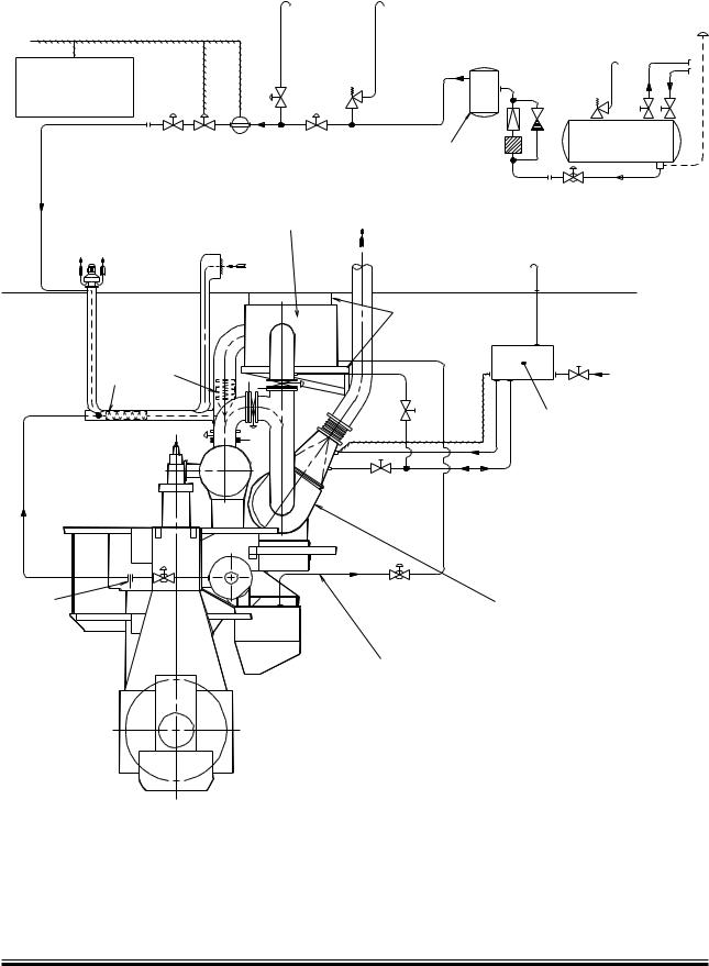
The amount of ammonia injected into the exhaust gas is controlled by a process computer and is based on the NOx production at different loads measured during the testbed running. Fig. 3.03.01.
As the ammonia is a combustible gas, it is supplied through a double walled pipe system, with appropriate venting and fitted with an ammonia leak detector (Fig. 3.03.01) which shows a simplified system layout of the SCR installation.
3.03
Page of 2
MAN B&W MC/MC-C/ME/ME-C/ME-GI/ME-B Engines
MAN Diesel |
198 58 94-7.1 |
|
MAN B&W |
3.03 |
|
|
Page |
of 2 |
Air
Process computer
Evaporator |
Ammonia |
|
tank |
||
|
SCR reactor
Air outlet |
Air intake |
|
Exhaust gas outlet |
||
|
||
|
Deck |
|
|
Support |
Static mixer
NOx and O2 analysers
Air
Orifice
High efficiency turbocharger
Preheating and sealing oil
Engine
198 99 27 1.0
Fig. 3.03.01: Layout of SCR system
MAN B&W MC/MC-C/ME/ME-C/ME-GI/ME-B Engines
MAN Diesel |
198 58 94-7.1 |
|

MAN B&W
Electricity Production
4
MAN Diesel