

s90mec7
.pdfMAN B&W |
1.04 |
|
|
|
Page of 2 |
Engine Power Range and Fuel Oil Consumption
Engine Power
The following tables contain data regarding the power, speed and specific fuel oil consumption of the engine.
Engine power is specified in kW for each cylinder number and layout points L1, L2, L3 and L4:
Discrepancies between kW and metric horsepower (1 BHP = 75 kpm/s = 0.7355 kW) are a consequence of the rounding off of the BHP values.
L1 designates nominal maximum continuous rating (nominal MCR), at 100% engine power and 100% engine speed.
L2, L3 and L4 designate layout points at the other three corners of the layout area, chosen for easy reference.
0OWER |
, |
, |
|


 ,
,
, 


3PEED
178 51 48 9.0
Fig. 1.04.01: Layout diagram for engine power and speed
Specific fuel oil consumption (SFOC)
Specific fuel oil consumption values refer to brake power, and the following reference conditions:
ISO 3046/1 2002: |
|
Blower inlet temperature................................. |
25°C |
Blower inlet pressure.............................. |
1000 mbar |
Charge air coolant temperature..................... |
25 °C |
Fuel oil lower calorific value................ |
42,700 kJ/kg |
|
(~10,200 kcal/kg) |
Although the engine will develop the power specified up to tropical ambient conditions, specific fuel oil consumption varies with ambient conditions and fuel oil lower calorific value. For calculation of these changes, see Chapter 2.
SFOC guarantee
The figures given in this project guide represent the values obtained when the engine and turbocharger are matched with a view to obtaining the lowest possible SFOC values and in compliance with the IMO NOx emission limitations, i.e. the so called ‘fuel economy mode’.
The Specific Fuel Oil Consumption (SFOC) is guaranteed for one engine load (power speed combination), this being the specified MCR rating.
The guarantee is given with a margin of 5%.
Overload corresponds to 110% of the power at MCR, and may be permitted for a limited period of one hour every 12 hours.
The engine power figures given in the tables remain valid up to tropical conditions at sea level as stated in IACS M28 (1978), i.e.:
Blower inlet temperature |
................................45 °C |
Blower inlet pressure.............................. |
1000 mbar |
Seawater temperature.................................... |
32 °C |
Relative humidity.............................................. |
60% |
If the ‘NOx emission mode’ is applied the SFOC is somewhat higher than for ‘fuel economy mode’, as mentioned in section 16.01. An estimation of the SFOC is stated in the following table.
Please note that the SFOC figures for ‘NOx emission mode’ are not subject to any guarantee.
Lubricating oil data
The cylinder oil consumption figures stated in the tables are valid under normal conditions.
During running in periods and under special conditions, feed rates of up to 1.5 times the stated values should be used.
MAN B&W ME/ME-B/ME C engines
MAN Diesel |
198 46 34 3.3 |
|

MAN B&W Diesel A/S |
1.04 |
|
|
Page 2 of 2
Comparison of SFOC for ‘Fuel Economy Mode’ and ‘NOx Emission Mode’
ME engines
|
|
Fuel economy mode |
|
|
NOx emission mode* |
|
||||
|
High efficiency |
Conventional |
|
High efficiency |
Conventional |
|||||
|
Load g/kWh |
Load g/kWh |
|
Load g/kWh |
Load g/kWh |
|||||
|
100% |
70% |
100% |
70% |
|
100% |
70% |
100% |
70% |
|
|
|
|
|
|
|
|
|
|
|
|
S90ME-C |
167 |
|
162 |
n.a. |
|
S90ME-C |
168-169 |
167-168 |
|
n.a. |
|
|
|
|
|
|
|
|
|
|
|
* Guiding figures not subject to SFOC guarantee n.a.: not applicable
Fig. 1.04.01: Comparison of SFOC
S90ME-C |
198 46 18-8.0 |
MAN B&W Diesel A/S |
1.05 |
|
|
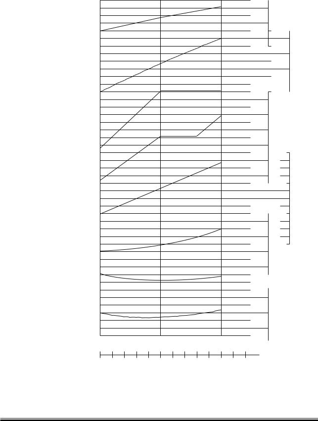
Performance Curves
Engine speed
Mean effective pressure
Maximum pressure
Compression pressure
Scavenge air pressure
Exhaust gas temperature inlet to turbocharger
Exhaust gas temperature outlet from turbocharger
Specific fuel oil consumption
Page 1 of 1
|
|
|
80 |
r/min |
|
|
|
|
|
70 |
|
bar |
|
|
|
|
|
|
|
|
|
|
|
60 |
|
20 |
|
|
|
|
50 |
|
18 |
|
|
|
|
|
|
16 |
MEP |
|
|
|
|
|
14 |
|
|
|
|
bar (abs) |
|
|
|
|
|
|
150 |
|
12 |
|
|
|
|
140 |
P-Max |
|
|
|
|
|
130 |
|
|
|
|
|
|
|
|
|
|
|
|
|
120 |
|
bar |
|
|
|
|
|
P-Comp |
(abs) |
|
|
|
|
110 |
4 |
|
|
|
|
|
100 |
|
|
|
|
|
|
|
|
|
|
|
|
|
90 |
|
3 |
P-Scav |
|
|
|
deg C |
|
||
|
|
|
|
|
||
|
|
|
450 |
|
2 |
|
|
|
|
400 |
Temp. |
|
|
|
|
|
|
|
|
|
|
|
|
350 |
Exh. Gas |
1 |
|
|
|
|
300 |
|
|
|
|
|
|
250 |
|
|
|
|
|
|
g/kWh |
|
|
|
|
|
|
180 |
|
|
|
|
|
|
170 |
SFOC |
|
|
|
|
|
160 |
|
|
|
|
|
|
150 |
|
|
|
50% |
75% |
100% |
Load |
|
|
|
1940 |
2910 |
3880 |
kW/cyl |
|
|
|
|
|
|
|
|
|
178 51 58-5.0 |
Fig. 1.05.01: Performance curves
S90ME-C |
198 46 71-3.0 |

MAN B&W |
1.06 |
|
|
ME Engine Description
Please note that engines built by our licensees are in accordance with MAN Diesel drawings and standards but, in certain cases, some local standards may be applied; however, all spare parts are interchangeable with MAN Diesel designed parts.
Some components may differ from MAN Diesel’s design because of local production facilities or the application of local standard components.
In the following, reference is made to the item numbers specified in the ‘Extent of Delivery’ (EoD) forms, both for the ‘Basic’ delivery extent and for some ‘Options’.
Bedplate and Main Bearing
The bedplate is made with the thrust bearing in the aft end of the engine. The bedplate consists of high, welded, longitudinal girders and welded cross girders with cast steel bearing supports.
For fitting to the engine seating in the ship, long, elastic holding down bolts, and hydraulic tightening tools are used.
The bedplate is made without taper for engines mounted on epoxy chocks.
The oil pan, which is made of steel plate and is welded to the bedplate, collects the return oil from the forced lubricating and cooling oil system. The oil outlets from the oil pan are normally vertical and are provided with gratings.
Horizontal outlets at both ends can be arranged for some cylinder numbers, however this must be confirmed by the engine builder.
The main bearings consist of thin walled steel shells lined with bearing metal. The main bearing bottom shell can be rotated out and in by means of special tools in combination with hydraulic tools for lifting the crankshaft. The shells are kept in position by a bearing cap.
Page of 5
Frame Box
The frame box is of welded design. On the exhaust side, it is provided with relief valves for each cylinder while, on the manoeuvring side, it is provided with a large hinged door for each cylinder. The crosshead guides are welded on to the frame box.
The frame box is attached to the bedplate with screws. The bedplate, frame box and cylinder frame are tightened together by stay bolts.
Cylinder Frame and Stuffing Box
The cylinder frame is cast, with the exception of the S65ME C which is welded, and is provided with access covers for cleaning the scavenge air space, if required, and for inspection of scavenge ports and piston rings from the manoeuvring side. Together with the cylinder liner it forms the scavenge air space.
The cylinder frame is fitted with pipes for the piston cooling oil inlet. The scavenge air receiver, turbocharger, air cooler box and gallery brackets are located on the cylinder frame. At the bottom of the cylinder frame there is a piston rod stuffing box, provided with sealing rings for scavenge air, and with oil scraper rings which prevent crankcase oil from coming up into the scavenge air space.
Drains from the scavenge air space and the piston rod stuffing box are located at the bottom of the cylinder frame.
Cylinder Liner
The cylinder liner is made of alloyed cast iron and is suspended in the cylinder frame with a low situated flange. The top of the cylinder liner is fitted with a cooling jacket. The cylinder liner has scavenge ports and drilled holes for cylinder lubrication.
MAN B&W ME/ME C engines
MAN Diesel |
198 46 13 9.4 |
|

MAN B&W |
1.06 |
|
|
Cylinder Cover
The cylinder cover is of forged steel, made in one piece, and has bores for cooling water. It has a central bore for the exhaust valve, and bores for the fuel valves, a starting valve and an indicator valve.
The cylinder cover is attached to the cylinder frame with studs and nuts tightened with hydraulic jacks.
Crankshaft
The crankshaft is of the semi built type, made from forged or cast steel throws. At the aft end, the crankshaft is provided with the collar for the thrust bearing, a flange for fitting the gear wheel for the step up gear to the hydraulic power supply unit if fitted on the engine, and the flange for the turning wheel and for the coupling bolts to an intermediate shaft.
At the front end, the crankshaft is fitted with the collar for the axial vibration damper and a flange for the fitting of a tuning wheel. The flange can also be used for a Power Take Off, if so desired.
Coupling bolts and nuts for joining the crankshaft together with the intermediate shaft are not normally supplied.
Thrust Bearing
The propeller thrust is transferred through the thrust collar, the segments, and the bedplate, to the end chocks and engine seating, and thus to the ship’s hull.
The thrust bearing is located in the aft end of the engine. The thrust bearing is of the B&W Michell type, and consists primarily of a thrust collar on the crankshaft, a bearing support, and segments of steel lined with white metal. The thrust shaft is an integrated part of the crankshaft and it is lubricated by the engine’s lubricating oil system.
Page of 5
Step up Gear
In case of engine driven HPS, the hydraulic oil pumps are mounted on the aft of the engine, and are driven from the crankshaft via step up gear. The step up gear is lubricated from the main engine system.
Turning Gear and Turning Wheel
The turning wheel is fitted to the thrust shaft, and it is driven by a pinion on the terminal shaft of the turning gear, which is mounted on the bedplate. The turning gear is driven by an electric motor with built in gear with brake.
A blocking device prevents the main engine from starting when the turning gear is engaged. Engagement and disengagement of the turning gear is effected manually by an axial movement of the pinion.
The control device for the turning gear, consisting of starter and manual control box, can be ordered as an option.
Axial Vibration Damper
The engine is fitted with an axial vibration damper, mounted on the fore end of the crankshaft. The damper consists of a piston and a split type housing located forward of the foremost main bearing. The piston is made as an integrated collar on the main journal, and the housing is fixed to the main bearing support.
Tuning Wheel / Torsional Vibration Damper
A tuning wheel or torsional vibration damper may have to be ordered separately, depending on the final torsional vibration calculations.
MAN B&W ME/ME C engines
MAN Diesel |
198 46 13 9.4 |
|

MAN B&W |
1.06 |
|
|
Connecting Rod
The connecting rod is made of forged or cast steel and provided with bearing caps for the crosshead and crankpin bearings.
The crosshead and crankpin bearing caps are secured to the connecting rod with studs and nuts tightened by means of hydraulic jacks.
The crosshead bearing consists of a set of thin walled steel shells, lined with bearing metal. The crosshead bearing cap is in one piece, with an angular cut out for the piston rod.
The crankpin bearing is provided with thin walled steel shells, lined with bearing metal. Lube oil is supplied through ducts in the crosshead and connecting rod.
Piston
The piston consists of a piston crown and piston skirt. The piston crown is made of heat resistant steel and has four ring grooves which are hard chrome plated on both the upper and lower surfaces of the grooves.
The uppermost piston ring is of the CPR type (Controlled Pressure Relief), whereas the other three piston rings are with an oblique cut. The uppermost piston ring is higher than the others. The piston skirt is of cast iron with a bronze band.
Piston Rod
The piston rod is of forged steel and is surfacehardened on the running surface for the stuffing box. The piston rod is connected to the crosshead with four screws. The piston rod has a central bore which, in conjunction with a cooling oil pipe, forms the inlet and outlet for cooling oil.
Page of 5
Crosshead
The crosshead is of forged steel and is provided with cast steel guide shoes with white metal on the running surface.
The telescopic pipe for oil inlet and the pipe for oil outlet are mounted on the guide shoes.
Scavenge Air System
The air intake to the turbocharger takes place directly from the engine room through the turbocharger intake silencer. From the turbocharger, the air is led via the charging air pipe, air cooler and scavenge air receiver to the scavenge ports of the cylinder liners, see Chapter 14.
Scavenge Air Cooler
For each turbocharger is fitted a scavenge air cooler of the mono block type designed for seawater cooling at up to 2.0 2.5 bar working pressure, alternatively, a central cooling system can be chosen with freshwater of maximum 4.5 bar working pressure.
The scavenge air cooler is so designed that the difference between the scavenge air temperature and the water inlet temperature at specified MCR can be kept at about 12 °C.
Auxiliary Blower
The engine is provided with electrically driven scavenge air blowers. The suction side of the blowers is connected to the scavenge air space after the air cooler.
Between the air cooler and the scavenge air receiver, non return valves are fitted which automatically close when the auxiliary blowers supply the air.
MAN B&W ME/ME C engines
MAN Diesel |
198 46 13 9.4 |
|

MAN B&W |
1.06 |
|
|
The auxiliary blowers will start operating consecutively before the engine is started in order to ensure sufficient scavenge air pressure to obtain a safe start.
Further information is given in Chapter 14.
Exhaust Turbocharger
The engines can be fitted with either MAN Diesel, ABB or Mitsubishi turbochargers.
The turbocharger choice is described in Chapter 3, and the exhaust gas system in Chapter 15.
Reversing
Reversing of the engine is performed electronically, by changing the timing of the fuel injection, the exhaust valve activation and the starting valves.
The Hydraulic Power Supply
The hydraulic power supply (HPS) is fitted on the aft end, and at the middle for engines with chain drive located in the middle, ie. large cylinder numbers. For engines with chain drive aft, the HPS is located aft.
Hydraulic Cylinder Unit
The hydraulic cylinder unit (HCU), one per cylinder, consists of a support console on which a distributor block is mounted. The distributor block is fitted with a number of accumulators to ensure that the necessary hydraulic oil peak flow is available for the Electronic Fuel Injection.
The distributor block serves as a mechanical support for the hydraulically activated fuel pressure booster and the hydraulically activated exhaust valve actuator.
Page of 5
Fuel Oil Pressure Booster and
Fuel Oil High Pressure Pipes
The engine is provided with one hydraulically activated fuel oil pressure booster for each cylinder.
Fuel injection is activated by a proportional valve, which is electronically controlled by the Cylinder Control Unit.
Further information is given in Section 7.01.
Fuel Valves and Starting Air Valve
The cylinder cover is equipped with two or three fuel valves, starting air valve, and indicator cock.
The opening of the fuel valves is controlled by the high pressure fuel oil created by the fuel oil pressure booster, and the valves are closed by a spring.
An automatic vent slide allows circulation of fuel oil through the valve and high pressure pipes when the engine is stopped. The vent slide also prevents the compression chamber from being filled up with fuel oil in the event that the valve spindle sticks. Oil from the vent slide and other drains is led away in a closed system.
The fuel oil high pressure pipes are equipped with protective hoses and are neither heated nor insulated.
The mechanically driven starting air distributor used on the MC engines has been replaced by one solenoid valve per cylinder, controlled by the CCUs of the Engine Control System.
Slow turning before starting is a program incorporated into the basic Engine Control System.
The starting air system is described in detail in Section 13.01.
The starting valve is opened by control air and is closed by a spring. The integrated Engine Control System controls the starting valve timing.
MAN B&W ME/ME C engines
MAN Diesel |
198 46 13 9.4 |
|

MAN B&W |
1.06 |
|
|
Page |
of 5 |
Exhaust Valve
The exhaust valve consists of the valve housing and the valve spindle. The valve housing is made of cast iron and is arranged for water cooling. The housing is provided with a water cooled bottom piece of steel with a flame hardened seat. The exhaust valve spindle is made of Nimonic. The housing is provided with a spindle guide.
The exhaust valve is tightened to the cylinder cover with studs and nuts. The exhaust valve is opened hydraulically by the electronic valve activation system and is closed by means of air pressure.
The operation of the exhaust valve is controlled by the proportional valve which also activates the fuel injection.
In operation, the valve spindle slowly rotates, driven by the exhaust gas acting on small vanes fixed to the spindle.
Indicator Cock
The engine is fitted with an indicator cock to which the PMI pressure transducer can be connected.
MAN Diesel Alpha Cylinder Lubricator
The electronically controlled Alpha cylinder lubricating oil system, used on the MC engines, is applied to the ME engines, and controlled by the ME Engine Control System.
The main advantages of the Alpha cylinder lubricating oil system, compared with the conventional mechanical lubricator, are:
•Improved injection timing
•Increased dosage flexibility
•Constant injection pressure
•Improved oil distribution in the cylinder liner
•Possibility for prelubrication before starting.
More details about the cylinder lubrication system can be found in Chapter 9.
Gallery Arrangement
The engine is provided with gallery brackets, stanchions, railings and platforms (exclusive of ladders). The brackets are placed at such a height as to provide the best possible overhauling and inspection conditions.
Some main pipes of the engine are suspended from the gallery brackets, and the topmost gallery platform on the manoeuvring side is provided with overhauling holes for the pistons.
The engine is prepared for top bracings on the exhaust side, or on the manoeuvring side.
Piping Arrangements
The engine is delivered with piping arrangements for:
•Fuel oil
•Heating of fuel oil pipes
•Lubricating oil, piston cooling oil and hydraulic oil pipes
•Cylinder lubricating oil
•Cooling water to scavenge air cooler
•Jacket and turbocharger cooling water
•Cleaning of turbocharger
•Fire extinguishing in scavenge air space
•Starting air
•Control air
•Oil mist detector
•Various drain pipes.
All piping arrangements are made of steel piping, except the control air and steam heating of fuel pipes, which are made of copper.
The pipes are provided with sockets for local instruments, alarm and safety equipment and, furthermore, with a number of sockets for supplementary signal equipment. Chapter 18 deals with the instrumentation.
MAN B&W ME/ME C engines
MAN Diesel |
198 46 13 9.4 |
|
MAN B&W Diesel A/S |
1.07 |
|
|
Page 1 of 1
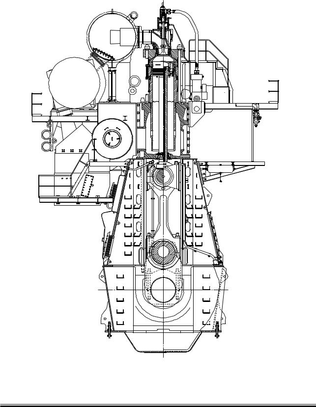
Engine Cross Section of S90ME-C
178 52 59-2.0
Fig.: 1.07.01
S90ME-C |
198 49 16-0.0 |