

s90mec7
.pdfMAN B&W |
5.16 |
|
|
Page |
of 4 |
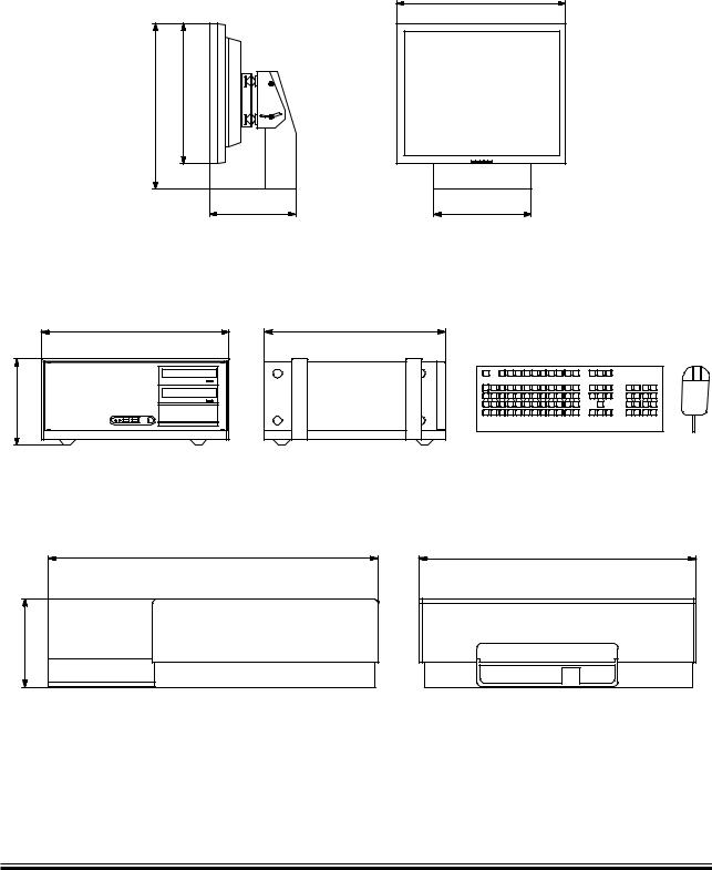
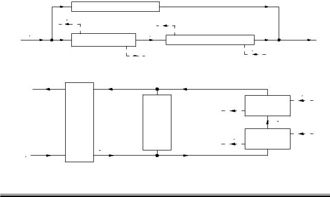
EICU (Engine Interface Control Unit) Cabinet
MOP PC unit
.OTEæ
|
|
|
|
.OTEæ æ
|
|
.OTE ææ#LEARANCEæFORæAIRæCOOLINGæ MMæ#LEARANCEæFORæ#ABLEæ æMM
178 50 14 7.1
Fig. 5.16.03 The EICU cabinet and MOP PC unit for the ME/ME-B Engine Control System
MAN B&W ME/ME-C/ME-GI/ME B engines
MAN Diesel |
198 46 97 7.4 |
|
MAN B&W |
5.16 |
|
|
PC parts for PMI/CoCoS
19” Display
|
|
|
|
Page of 4
PC unit |
|
|
|
|
|
Printer |
|
|
|
|
|
178 57 49-3.0
Fig. 5.16.04 PMI/CoCoS PC unit, display and printer for the ME/ME-B Engine Control System
MAN B&W ME/ME-C/ME-GI/ME B engines
MAN Diesel |
198 46 97 7.4 |
|
MAN B&W |
5.17 |
|
|
Shaftline Earthing Device
Scope and field of application
A difference in the electrical potential between the hull and the propeller shaft will be generated due to the difference in materials and to the propeller being immersed in sea water.
In some cases, the difference in the electrical potential has caused spark erosion on the thrust, main bearings and journals of the crankshaft of the engine.
In order to reduce the electrical potential between the crankshaft and the hull and thus prevent spark erosion, a highly efficient shaftline earthing device must be installed.
The shaftline earthing device should be able to keep the electrical potential difference below 50 mV DC, and a shaft-to-hull monitoring equipment with an mV-meter and with an output signal to the alarm system must be installed so that the potential and thus the correct function of the shaftline earthing device can be monitored.
Note that only one shaftline earthing device is needed in the propeller shaft system.
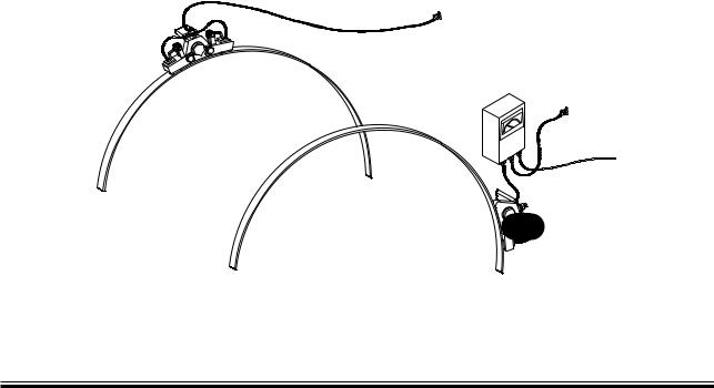
"RUSHæHOLDER ARRANGEMENT
3LIPæRING
3LIPæRING
FORæMONITORING EQUIPMENT
Fig. 5.17.01
Page 1 of 3
Design description of the shaftline earthing device
The shaftline earthing device consists of two silver slip rings, two arrangements for holding brushes including connecting cables and monitoring equipment with an mV-meter and an output signal for alarm.
The slip rings should be made of solid silver or back-up rings of cobber with a silver layer all over. The expected life span of the silver layer on the slip rings should be minimum 5 years.
The brushes should be made of minimum 80% silver and 20% graphite to ensure a sufficiently electrical conducting capability.
Resistivity of the silver should be less than 0.1μ Ohm x m. The total resistance from the shaft to the hull must not exceed 0.005 Ohm. For a wellfunctioning shaftline earthing device, the resistance is expected to be approximately 0.001 Ohm.
#ABLE CONNECTED TOæTHEæHULL
-ONITORING
EQUIPMENT
WITHæM6çMETER #ABLE CONNECTED TOæTHEæHULL
#ABLE
TOæALARM SYSTEM
"RUSHæHOLDER ARRANGEMENT
079 21 82-1.2.1.0
MAN B&W MC/MC C, ME-B/ME/ME C engines
MAN Diesel |
198 49 29 2.3 |
|
MAN B&W |
5.17 |
|
|
|
Page 2 of 3 |
A cable with a cross section not less than 45 mm² is used for cabling the shaftline earthing device to the hull. The length of the cable to the hull should be as short as possible.
Monitoring equipment should have a 4-20 mA signal for alarm and a two range mV-meter with a switch for changing range. Primary range from 0 mV to 50 -150 mV DC, and secondary range from 0 mV to 300-1500 mV DC.
When the shaftline earthing device is working correctly, the electrical potential will normally be within the range of 10-50 mV DC. The alarm setpoints should be 5 mV for a low alarm and 80 mV for a high alarm. The alarm signals with an alarm delay of 30 seconds and an alarm cut-off, when the engine is stopped, must be connected to the alarm system.
Connection of cables as shown on the sketch, Fig. 5.17.01.
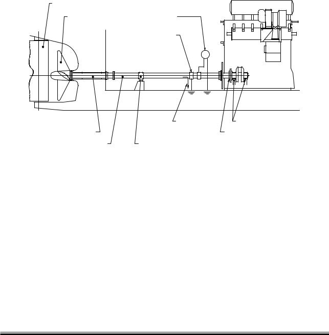
2UDDER |
|
|
|
6OLTAGEæMONITORINGæ |
|
|
FORæSHAFTçHULLæPOTENTIALæ |
|
0ROPELLER |
DIFFERENCE |
|
|
3HAFTLINE |
|
|
EARTHINGæDEVICE |
|
|
|
6 |
|
#URRENT |
-AINæBEARINGS |
0ROPELLERæSHAFT |
|
4HRUSTæBEARING |
)NTERMEDIATEæSHAFT |
)NTERMEDIATEæSHAFTæBEARING |
|
079 21 82-1.2.2.0
Fig. 5.17.02: The shaftline earthing device slip rings must be fitted on the foremost intermediate shaft as close to the engine as possible
MAN B&W MC/MC C, ME-B/ME/ME C engines
MAN Diesel |
198 49 29 2.3 |
|
MAN B&W |
5.17 |
|
|
Page 3 of 3
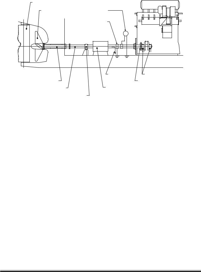
2UDDER |
|
|
|
6OLTAGEæMONITORINGæ |
|
|
FORæSHAFTçHULLæPOTENTIALæ |
|
0ROPELLER |
DIFFERENCE |
|
|
3HAFTLINE |
|
|
EARTHINGæDEVICE |
|
|
6 |
|
|
#URRENT |
-AINæBEARINGS |
0ROPELLERæSHAFT |
|
4HRUSTæBEARING |
)NTERMEDIATEæSHAFT |
3HAFTæMOUNTEDæALTERNATORæ |
|
|
WHEREæTHEæROTORæISæPARTæOFæ |
|
|
THEæINTERMEDIATEæSHAFT |
|
)NTERMEDIATEæSHAFTæBEARING |
|
|
079 21 82-1.2.3.0
Fig. 5.17.03: When a generator is fitted, the shaftline earthing device must be placed between the generator and the engine
Suppliers
Supplier ref. no. 1386:
BAC Corrosion Control A/S
Faeroevej 7-9
DK-4681 Herfoelge, Denmark
Telephone: +45 70 26 89 00
Telefax: +45 70 26 97 00
Email: info@bacbera.dk
Website: www.bacbera.dk
Supplier ref. no. 1606:
M. G. Duff Marie Limited 1 Timberlaine Estate
Gravel Lane, Quarry Lane, Chichester West Sussex, PO19 8PP, England Telephone: +44 1243 533 336 Telefax: +44 1243 533 422 Email: sales@mgduff.co.uk Website: www.mgduff.co.uk
MAN B&W MC/MC C, ME-B/ME/ME C engines
MAN Diesel |
198 49 29 2.3 |
|

MAN B&W |
5.18 |
|
|
|
Page of 1 |
MAN Diesel Controllable Pitch Propeller (CPP) and Remote Control
This section is not applicable
MAN Diesel |
198 61 57-3 .0 |
|

MAN B&W
List of Capacities:
Pumps, Coolers &
Exhaust Gas
6
MAN Diesel

MAN B&W |
6.01 |
|
|
|
Page of 1 |
Calculation of List of Capacities and Exhaust Gas Data
This chapter describes the necessary auxiliary machinery capacities to be used for a nominally rated engine. The capacities given are valid for seawater cooling system and central cooling water system, respectively. For derated engine, i.e. with a specified MCR and/or matching point different from the nominally rated MCR point, the list of capacities will be different from the nominal capacities.
Furthermore, among others, the exhaust gas data depends on the ambient temperature conditions.
Based on examples for a derated engine, the way of how to calculate the derated capacities, freshwater production and exhaust gas amounts and temperatures will be described in details.
Nomenclature
In the following description and examples of the auxiliary machinery capacities, freshwater generator pro-
Engine ratings |
Point / Index |
Power |
Speed |
|
|
|
|
Nominal MCR point |
L1 |
PL1 |
nL1 |
Specified MCR point |
M |
PM |
nM |
Matching point |
O |
PO |
nO |
Service point |
S |
PS |
nS |
|
Parameters |
|
Cooler index |
|
Flow index |
|
|
|
|
|
|
|
|
Q |
= |
Heat dissipation |
air |
scavenge air cooler |
sw |
seawater flow |
|
|
|
|
|
|
|
V |
= |
Volume flow |
lub |
lube oil cooler |
cw |
cooling/central water flow |
|
|
|
|
|
|
|
M |
= |
Mass flow |
jw |
jacket water cooler |
exh |
exhaust gas |
|
|
|
|
|
|
|
T |
= |
Temperature |
cent |
central cooler |
fw |
freshwater |
|
|
|
|
|
|
|
Fig. 6.01.02: Nomenclature of coolers and volume flows, etc.
Engine configurations related to SFOC
For S70ME C/ME GI, L70ME C, S65ME C/ME GI, S60ME C/ME GI, L60ME C, S50ME C
The engine type is available in the following two versions with respect to the efficiency of the turbocharger:
•A) With high efficiency turbocharger, case A: which is the basic design and for which the lists of capacities Section 6.03 are calculated.
•B) With conventional turbocharger, case B:
Which is an optional design (EoD No. 4 59 107) if a higher exhaust gas temperature is required for the exhaust gas boiler. This modification will lead to a 7 8% reduction in the exhaust gas amount and a temperature increase of about 20°C. The SFOC penalty will be 2 g/kWh, see example in Fig. 6.01.03. The corresponding lists of capacities are shown in Section 6.03.
3&/#æ |
|
|
|
|
|
|
|
|
|
|
|
|
|
|
|
|
G K7Hæ |
|
|
|
|
|
|
|
|
|
|
" |
|
! |
|
||
|
|
|
|
|
|
|
|
|
|
|
|
|
|
|||
|
|
|
|
|
|
|
|
|
|
|
|
|
|
|
|
|
|
|
|
|
|
|
|
|
|
|
|
|
|
|
|
|
|
|
|
|
|
|
|
|
|
|
|
|
|
|
|
|
|
|
|
|
|
|
|
|
|
|
|
|
|
|
|
|
|
|
|
|
|
|
|
|
|
|
|
|
|
|
|
|
|
|
|
|
|
|
|
|
|
|
|
|
|
|
|
|
|
|
|
|
|
|
|
|
|
|
|
|
|
|
|
|
|
|
|
|
|
|
ç |
|
|
|
|
|
|
|
|
|
|
|
|
|
|
|
|
|
|
|
|
|
|
|
|
|
|
|
|
|
|
|
|
|
|
|
|
#ONVENTIONALæTURBOCHARGER |
|
|
|
|
|
|
|
|
|
|
|||
ç |
|
|
|
|
|
|
|
|
|
|
|
|
|
|
|
|
|
|
|
|
|
|
|
|
|
|
|
|
|
|
|
|
|
|
|
|
|
|
|
|
|
|
|
|
|
|
|
|
|
|
ç |
|
|
|
|
|
|
|
|
|
|
|
|
|
|
|
|
|
|
|
|
|
|
|
|
|
|
|
|
|
|
|
|
|
|
|
|
|
|
|
|
|
|
|
|
|
|
|
|
|
|
ç |
|
|
|
|
|
|
|
|
|
(IGHæEFFICIENCYæTURBOCHARGER |
|
|
|
|||
|
|
|
|
|
|
|
|
|
|
|
|
|
|
|
|
|
ç |
|
|
|
|
|
|
|
|
|
|
|
|
|
|
|
|
|
|
|
|
|
|
|
|
|
|
|
|
|
|
|
|
|
æ |
æ |
æ |
æ |
æ |
æ |
|
æ |
|||||||||
|
|
|
|
|
|
|
|
|
|
|
|
|
198 96 82 4.5 |
|||
Fig. 6.01.03: SFOC curves for (A) high efficiency and
(B) conventional turbochargers, respectively
ME/ME C engines
MAN Diesel |
198 43 33 5.2 |
|
MAN B&W |
6.02 |
|
|
|
Page of 1 |
List of Capacities and Cooling Water Systems
The List of Capacities contain data regarding the necessary capacities of the auxiliary machinery for the main engine only, and refer to a nominally rated engine. Complying with IMO Tier I NOx limitations.
The heat dissipation figures include 10% extra margin for overload running except for the scavenge air cooler, which is an integrated part of the diesel engine.
Cooling Water Systems
The capacities given in the tables are based on tropical ambient reference conditions and refer to engines with high efficiency/conventional turbocharger running at nominal MCR (L1) for:
•Seawater cooling system,
See diagram, Fig. 6.02.01 and nominal capacities in Fig. 6.03.01
•Central cooling water system,
See diagram, Fig. 6.02.02 and nominal capacities in Fig. 6.03.01
The capacities for the starting air receivers and the compressors are stated in Fig. 6.03.01.
Heat radiation and air consumption
The radiation and convection heat losses to the engine room is around 1% of the engine nominal power (kW in L1).
The air consumption is approximately 98.2% of the calculated exhaust gas amount, ie. Mair = Mexh x 0.982.
Flanges on engine, etc.
The location of the flanges on the engine are shown in: ‘Engine pipe connections’, and the flanges are identified by reference letters stated in the ‘List of flanges’; both can be found in Chapter 5.
The diagrams use the ‘Basic symbols for piping’, whereas the symbols for instrumentation according to ‘ISO 1219 1’ and ‘ISO 1219 2’ and the instrumentation list found in Appendix A.
Scavenge air cooler |
|
|
|
45 C |
|
|
|
Seawater |
|
Seawater outlet |
|
32 C |
38 C |
||
Jacket water cooler |
|||
Lubricating oil cooler |
|
||
|
|
80 C |
Fig. 6.02.01: Diagram for seawater cooling system |
178 11 26 4.1 |
|
|
|
|
Seawater outlet |
|
|
|
|
80 C |
|
|
Jaket |
|
|
water |
|
Central |
cooler |
|
cooler |
|
|
Scavenge |
43 C |
|
air |
|
|
cooler (s) |
|
|
|
Lubricating |
|
45 C |
oil |
|
Central coolant |
cooler |
|
|
|
Seawater inlet |
36 C |
|
|
|
|
32 C |
|
|
Fig. 6.02.02: Diagram for central cooling water system |
178 11 27 6.1 |
|
|
|
|
MAN B&W MC, MC-C, ME, ME-B, ME-C, ME-GI engines
MAN Diesel |
198 50 42-8.3 |
|