Hydraulic Power Supply Unit
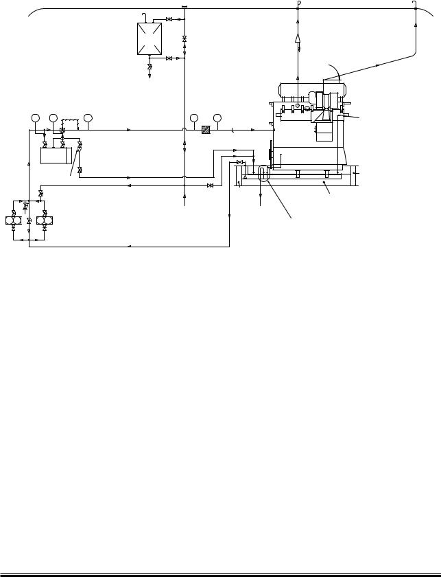
Internally on the engine RU is connected to the Hydraulic Power Supply unit (HPS) which supplies the hydraulic oil to the Hydraulic Cylinder Units (HCUs). The HPS unit can be either mounted onto the engine and engine driven (EoD 4 40 160) or delivered separately electrically driven, option 4 40 660. See figs. 16.01.02 and 16.01.03 respectively.
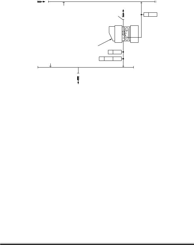
The hydraulic power supply unit shown in Fig. 8.02.01, consists of:
•an automatic main filter with a redundance filter, in parallel
•two electrically driven pumps
•three engine driven pumps
•an safety and accumulator block
RW is the oil outlet from the automatic backflushing filter.
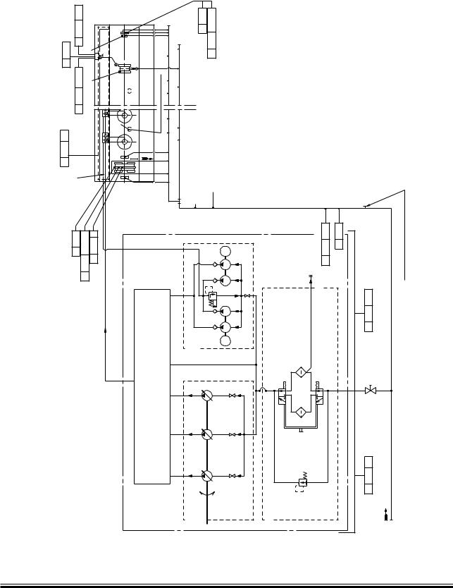
At start one of the two electrically driven start up pumps is activated, and it is stopped as soon as the three engine driven pumps have taken over the hydraulic oil supply.
The hydraulic oil is supplied to the Hydraulic Cylinder Units (HCU) located at each cylinder, where it is diverted to the electronic Fuel Injection system, and to the electronic exhaust Valve Activation (FIVA) sy stem, which perform the fuel injection and opens the exhaust valve. The exhaust valve is closed by the conventional ‘air spring’.
The electronic signals to the FIVA valves are given by the Engine Control System, see Chapter 16, Engine Control System (ECS).
Page of 2
The Hydraulic power supply is available in 2 versions
The standard version, EoD 4 40 660, is the classic ME power supply where the hydraulic power is generated by engine driven pumps and start up pressure is created by electric driven start pumps. The capacity of the start up pumps is only sufficient to make the start up pressure. The engine can not run with the engine driven pumps out of operation.
The optional version, EoD 4 40 661 is similar to the standard version, but the electric driven start up pumps have a capacity sufficient to give Take Home power at least 15% engine power. The electric power consumption should be taken into consideration in the specification of the auxilliary machinery capacity.


 RU
RU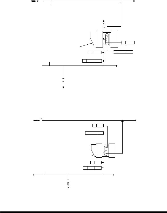


 !"
!" turbocharger