


3-14 ENGINE
ENGINE DISASSEMBLY
Identify the position of each removed part. Organize the parts in their respective groups (e.g., intake, exhaust) so that they can be reinstalled in their original positions.
• Remove the spark plugs. ( 2-5)
STARTER MOTOR
• Remove the starter motor 1.
CYLINDER HEAD COVER |
|
E |
|
• Remove the cylinder head cover 1 and its gaskets. |
|||
L |
|||
|
|
||
|
|
P |
|
|
M |
||
|
A |
|
|
|
S |
|
|
• Remove the PAIR reed valves 2 with their gaskets.
CAMSHAFT
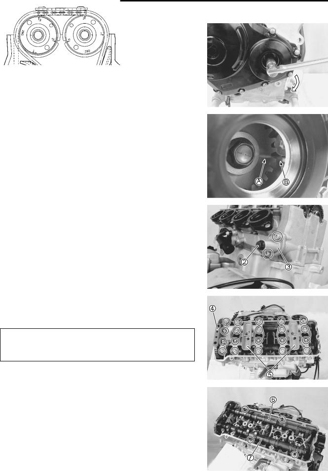
• Remove the valve timing inspection cap 1.
ENGINE 3-15
•Turn the crankshaft to bring the line A on the CKP sensor rotor to the rib B behind the clutch cover and also to bring the cams to the position as shown.
|
|
|
|
|
E |
|
|
|
|
|
|
• Remove the cam chain tension adjuster cap bolt 2 |
L |
||||
and |
|
||||
spring. |
|
|
P |
|
|
|
|
|
|
|
|
• Remove the cam chain tension adjuster 3. |
|
|
|
||
|
|
M |
|
|
|
|
|
A |
|
|
|
|
S |
|
|
|
|
•Remove the cam chain guide No. 2 4.
•Remove the camshaft journal holders 5.
Be sure to loosen the camshaft journal holder bolts evenly by shifting the wrench in the descending order of numbers.
•Remove the intake camshaft 6.
•Remove the exhaust camshaft 7.
•Remove the dowel pins.

3-16 ENGINE
CYLINDER HEAD
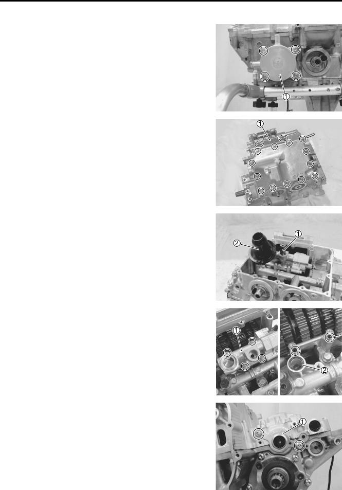
•Remove the thermostat cover 1.
•Remove the thermostat 2 and thermostat conector 3.
THERMOSTAT INSPECTION ( 7-9)
• Remove the ECT sensor 4.
ECT SENSOR INSPECTION ( 7-7)
• Remove the cylinder head bolts (M6) 5.
|
E |
• Remove the O-rings 6. |
L |
|
|
• Remove the cylinder head bolts and washers. |
|
NOTE: |
|
When loosening the cylinder head bolts, loosen each boltPlittle |
|
by little diagonally. |
M |
•Remove the cylinder head. A
•Remove the dowel pins andSgasket.
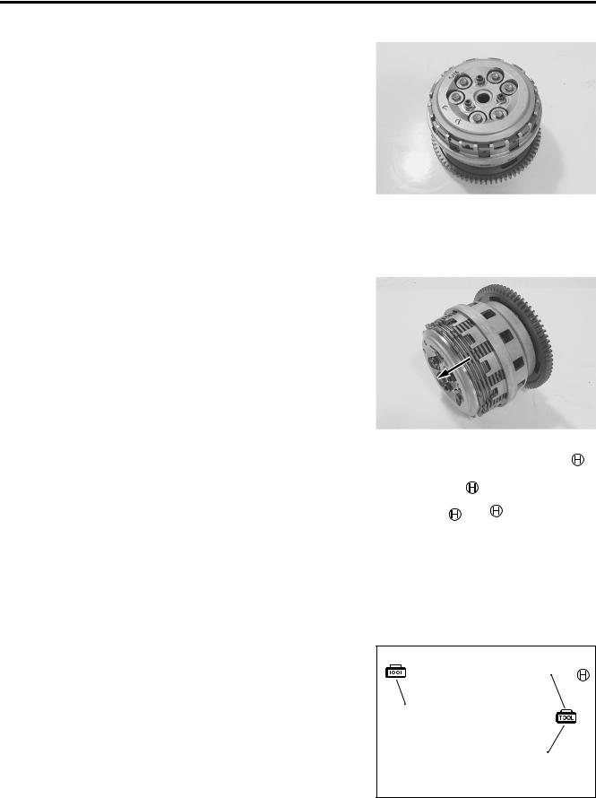
CLUTCH
•Remove the clutch cover 1 along with the CKP sensor 2.
•Remove the dowel pins and gasket.
CKP SENSOR INSPECTION ( 4-35)

ENGINE 3-17
• Hold the clutch housing with the special tool.
Do not damage the clutch plates by the special tool.
09920-53740: Clutch sleeve hub holder
• Remove the clutch springs.
NOTE:
Loosen the clutch spring set bolts little by little and diagonally.
•Remove the pressure plate 3.
•Remove the clutch drive plates 4 and driven plates 5.
•Remove the clutch push piece 6, thrust washer 7 and bearing 8.
|
|
|
E |
• Remove the spring washer 9 and its seat 0. |
P |
||
L |
|||
• Remove the clutch push rod A. |
M |
||
NOTE: |
|
||
A |
|
||
|
|
||
If it is difficult to pull out the push rod B, use a magnetic hand or |
|||
a wire. |
S |
|
|
|
|
|
|
• Unlock the clutch sleeve hub nut.
3-18 ENGINE
• Hold the clutch sleeve hub with the special tool.
09920-53740: Clutch sleeve hub holder
• Remove the clutch sleeve hub nut.
•Remove the washers C, D and E from the clutch sleeve hub.
|
|
E |
• Remove the wave spring washers F and clutch lifter driven |
L |
|
cam G. |
P |
|
|
|
|
|
M |
|
|
A |
|
|
S |
|
• Remove the clutch lifter drive cam H and washer I.
•Remove the spacer J and bearing K.
•Remove the primary driven gear assembly L.
NOTE:
If it is difficult to remove the primary driven gear, rotate the crankshaft.

ENGINE 3-19
OIL PUMP DRIVE SPROCKET
• Remove the spacer 1.
•Remove the oil pump drive sprocket 2 and chain 3.
•Remove the thrust washer 4.
GEARSHIFT SYSTEM
• With the snap ring 1 and washer removed, remove the gearshift shaft assembly 2.
|
|
|
E |
|
|
L |
|
• Remove the gearshift cam plate bolt 3 and gearshift cam |
|
||
plate 4. |
|
P |
|
|
|
|
|
• Remove the gearshift cam stopper 5. |
|
|
|
|
M |
|
|
|
A |
|
|
|
S |
|
|
STARTER IDLE GEAR AND GENERATOR COVER
• Remove the starter idle gear cover.
•Remove the spring washer 1, washer 2 and starter idle gear No. 1 3.

3-20 ENGINE
• Remove the shaft 4, bearing 5 and thrust washer 6.
• Remove the generator cover.
• Remove the dowel pins and gasket.
|
E |
• Remove the starter idle gear No. 2 7 and shaft 8. |
L |
|
P |
M |
|
A |
|
S |
|
CAM CHAIN/CAM CHAIN TENSIONER/CAM CHAIN GUIDE
•While holding the generator rotor with the special tool, remove the CKP sensor rotor/cam chain drive sprocket nut.
09930-44520: Rotor holder
•Remove the CKP sensor rotor/cam chain drive sprocket 1 and cam chain 2.
•Remove the cam chain tensioner 3 and cam chain guide No. 1 4.

ENGINE 3-21
GENERATOR ROTOR AND STARTER DRIVEN GEAR
• Hold the generator rotor with the special tool.
09930-44520: Rotor holder
• Remove the generator rotor bolt.
• Install a bolt A of suitable size to the left end of crankshaft.
SUITABLE BOLT A [M12, length: 28 – 38 mm (1.1 – 1.5 in)]
• Remove the generator rotor 1 and starter driven gear 2 with the special tool.
09930-34980: Rotor remover |
|
E |
28 – 38 mm (1.1 – 1.5 in) |
L |
|
P |
|
M |
|
A |
|
S |
|
WATER PUMP |
|
• Remove the water hoses and water inlet connector 1. |
|
• Remove the water pump 2.
WATER PUMP SERVICING ( 7-11)

3-22 ENGINE
GEAR POSITION SWITCH
• Remove the gear position switch 1.
CRANKCASE BREATHER (PCV) COVER
• Remove the crankcase breather cover 1.
|
E |
• Remove the gasket 2. |
L |
|
P |
|
M |
|
A |
OIL PRESSURE SWITCH |
S |
|
|
• Remove the oil pressure switch 1. |
|
OIL FILTER
• Remove the oil filter with the special tool.
09915-40610: Oil filter wrench
ENGINE 3-23
OIL COOLER
• Remove the oil cooler 1.
OIL PAN
• Remove the plate 1 and oil pan.
• Remove the gasket.
|
|
E |
|
OIL PRESSURE REGULATOR |
|
L |
|
• Remove the oil pressure regulator 1. |
P |
||
OIL STRAINER |
|
||
M |
|||
• Remove the oil strainer 2. |
|||
A |
|
||
S |
|
|
|
OIL PUMP
•Remove the oil pump 1.
•Remove the dowel pins and O-ring 2.
LOWER CRANKCASE
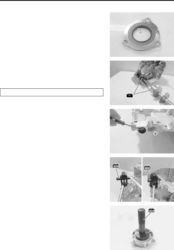
• Remove the clutch push rod oil seal retainer 1.

3-24 ENGINE
• Remove the upper crankcase bolts.
• Remove the lower crankcase bolts (M8).
• Remove the crankshaft journal bolts (M9).
• Remove the lower crankcase assembly.
|
E |
• Remove the dowel pins, O-ring 2 and cap 3. |
L |
|
P |
M |
|
A |
|
S |
|
COUNTERSHAFT
•Remove the dowel pin.
•Remove the retainer 1, bushing 2, gearshift shaft and fork
3.
•Remove the oil seal 4 and countershaft assembly 5.
• Remove the C-ring 6 and bearing pin 7.

ENGINE 3-25
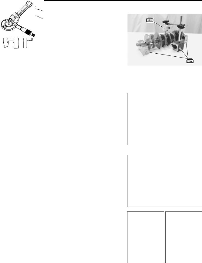
CRANKSHAFT
• Loosen the conrod bearing cap bolts by using a 10 mm, 12-point socket wrench, and tap the bearing cap bolts lightly with a plastic hammer to remove the bearing cap.
• Remove the crankshaft and thrust bearings 1.
PISTON AND CONROD
•Push the conrod to cylinder head side and remove the piston and conrod from the upper crankcase.
Be careful not to damage the cylinder wall by the conrod.
E
L
P
M
A
S
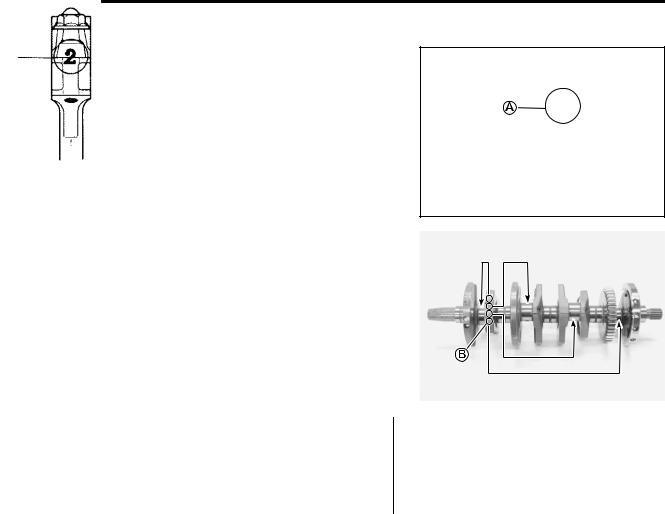
• Remove the piston pin circlip 1.
• Separate the piston and conrod by driving out the piston pin.
NOTE:
Scribe the cylinder number on the piston head.

3-26 ENGINE
ENGINE COMPONENTS INSPECTION
AND SERVICE
Identify the position of each removed part. Organize the parts in their respective groups (i.e., intake, exhaust, No.1 or No.2) so that they can be installed in their original locations.
CYLINDER HEAD COVER
•Clean and check the gasket grooves A and PAIR reed valve gasket mating surfaces B of cylinder head cover.
•If it is damaged, replace the cylinder head cover with a new one.
CMP SENSOR |
|
|
E |
|
|
L |
|
REMOVAL |
|
|
|
• Remove the CMP sensor 1 from the cylinder head cover. |
|||
INSPECTION |
|
P |
|
|
M |
|
|
• Inspect the CMP sensor. ( 4-33) |
|
||
|
|
|
|
|
A |
|
|
|
S |
|
|
INSTALLATION
• Install the CMP sensor.
NOTE:
When installing, clean the CMP sensor’s face.
CMP sensor mounting bolt: 10 N·m (1.0 kgf-m, 7.0 lb-ft)
PAIR REED VALVE
REMOVAL
• Remove the PAIR reed valve 1 from the gasket.

ENGINE 3-27
INSPECTION
•Inspect the reed valve for the carbon deposit.
•If the carbon deposit is found in the reed valve, replace the PAIR reed valve with a new one.
CRANKCASE BREATHER REED VALVE
REMOVAL
• Remove the crankcase breather reed valve 1 from the crankcase breather cover.
|
|
|
E |
INSPECTION |
|
L |
|
• Inspect the reed valve for the carbon deposit. |
P |
|
|
• If the carbon deposit is found in the reed valve, replace the |
|
||
crankcase breather reed valve with a new one. |
|
|
|
M |
|
|
|
A |
|
|
|
S |
|
|
|
INSTALLATION
•Install the reed valve to the breather cover.
•Tighten the bolts to the specified torque.
Crankcase breather reed valve cover bolt:
10 N·m (1.0 kgf-m, 7.0 lb-ft)
PCV HOSE
•Remove the PCV hose from the crankcase breather reed valve cover.
•Inspect the PCV hose for wear or damage.
•If it is worn or damaged, replace the PCV hose with a new one.
3-28 ENGINE
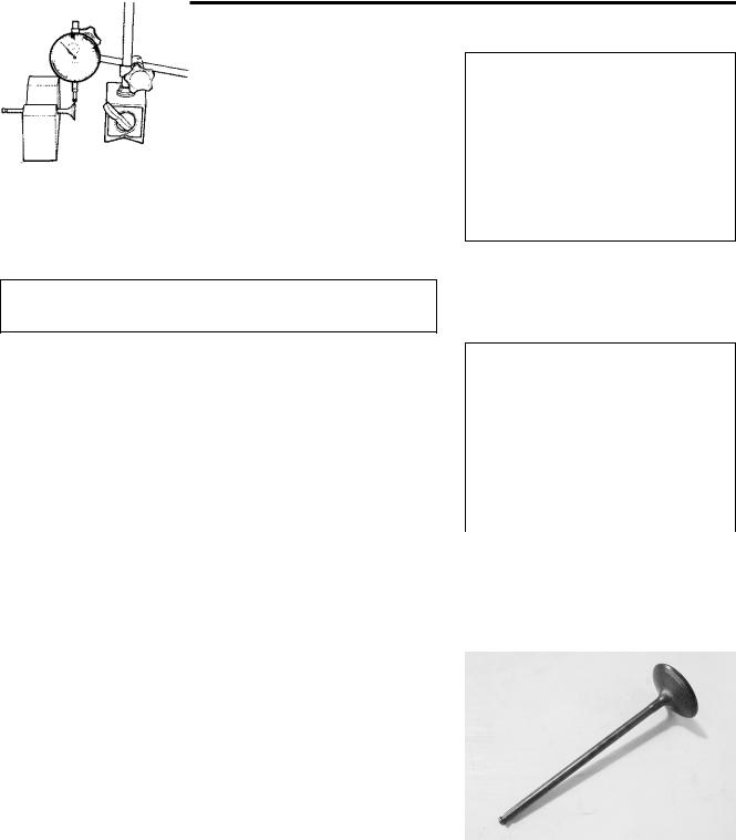
CAMSHAFT
CAMSHAFT IDENTIFICATION
The exhaust camshaft can be distinguished from that of the intake by the embossed letters “EX” (for exhaust) as against letters “IN” (for intake).
CAM WEAR
•Check the camshaft for wear or damage.
•Measure the cam height H with a micrometer.
Cam height H:
Service Limit: (IN.) : 36.28 mm (1.428 in) (EX.) : 35.68 mm (1.405 in)
09900-20202: Micrometer (25 – 50 mm)
|
|
|
E |
|
|
|
|
|
|
CAMSHAFT JOURNAL WEAR |
|
L |
|
|
• Determine whether or not each journal is worn down to the |
|
|
|
|
|
P |
|
||
limit by measuring the oil clearance with the camshaft |
|
|
|
|
installed in place. |
M |
|
|
|
• Use the plastigauge 1 to read the clearance at the widest |
|
|
|
|
portion, which is specified as follows: |
|
|
|
|
Camshaft journal oil clearance: |
|
|
|
|
Service Limit: (IN. & EX.): 0.150Amm (0.0059 in) |
|
|
|
|
09900-22301: PlastigaugeS |
|
|
|
|
|
|
|
|
|
09900-22302: Plastigauge |
|
|
|
|
NOTE: |
|
|
|
|
Install camshaft journal holders to their original positions. |
|
|
|
|
( 3-93) |
|
|
|
|
•Tighten the camshaft journal holder bolts evenly and diagonally to the specified torque.
Camshaft journal holder bolt: 10 N·m (1.0 kgf-m, 7.0 lb-ft)

ENGINE 3-29
NOTE:
Do not rotate the camshaft with the plastigauge in place.
•Remove the camshaft holders, and read the width of the compressed plastigauge with envelope scale.
•This measurement should be taken at the widest part.
•If the camshaft journal oil clearance measured exceeds the limit, measure the inside diameter of the camshaft journal holder and outside diameter of the camshaft journal.
•Replace the camshaft or the cylinder head depending upon which one exceeds the specification.
Camshaft journal holder I.D.:
Standard: (IN. & EX.):
24.012 – 24.025 mm (0.9454 – 0.9459 in)
09900-20602: Dial gauge (1/1000, 1 mm) |
|
|
|
E |
|
09900-22403: Small bore gauge (18 – 35 mm) |
|
|
|||
L |
|||||
|
|
||||
Camshaft journal O.D.: |
P |
|
|
||
Standard (IN. & EX.): |
|
|
|
|
|
M |
|
|
|
||
23.959 – 23.980 mm (0.9433 – 0.9441 in) |
|
|
|||
09900-20205: Micrometer (0 – 25 mm) |
|
|
|
|
|
A |
|
|
|
|
|
S |
|
|
|
|
|
|
|
|
|
||
CAMSHAFT RUNOUT
•Measure the runout using the dial gauge.
•Replace the camshaft if the runout exceeds the limit.
Camshaft runout:
Service Limit (IN. & EX.): 0.10 mm (0.004 in)
09900-20607: Dial gauge (1/100 mm)
09900-20701: Magnetic stand
09900-21304: V-block set (100 mm)
CAM SPROCKET
•Inspect the sprocket teeth for wear.
•If they are worn, replace the sprocket/camshaft assembly and cam chain as a set.

3-30 ENGINE
CAM CHAIN TENSION ADJUSTER
INSPECTION
• Remove the cam chain tension adjuster cap bolt and spring.
• Check that the push rod slides smoothly when releasing stopper 1.
• If it does not slide smoothly, replace the cam chain tension adjuster with a new one.
CAM CHAIN TENSIONER
INSPECTION
•Check the contacting surface of the cam chain tensioner.
•If it is worn or damaged, replace it with a new one.
CAM CHAIN GUIDE |
|
L |
|
E |
|
INSPECTION |
P |
|
|
|
|
• Check the contacting surfaces of the cam chain guide No. 1 |
|
|
and No. 2. |
M |
|
|
|
|
• If they are worn or damaged, replace them with the new ones. |
|
|
|
A |
|
|
S |
|
CYLINDER HEAD AND VALVE
VALVE AND VALVE SPRING DISASSEMBLY
•Remove the tappet 1 and shim 2 by fingers or magnetic hand.
Identify the position of each removed part.

ENGINE 3-31
•Install the special tool 3 between the valve spring and cylinder head.
•Using the special tools, compress the valve spring and
remove the two cotter halves from the valve stem.
09916-14510: Valve lifter
09916-14530: Valve lifter attachment
09916-84511: Tweezers
09919-28610: Sleeve protector
To prevent damage of the tappet sliding surface with the special tool, use the protector.
•Remove the valve spring retainer 4 and valve spring 5.
•Pull out the valve 6 from the combustion chamber side.
|
|
E |
|
L |
|
|
P |
|
• Remove the oil seal 7 and spring seat 8. |
||
|
M |
|
Do not reuse the removed oil seal. |
|
|
|
A |
|
• Remove the other valves in the same manner as described |
||
|
S |
|
previously.
CYLINDER HEAD DISTORTION
•Decarbonize the combustion chambers.
•Check the gasketed surface of the cylinder head for distortion with a straightedge and thickness gauge, taking a clearance reading at several places indicated.
•If the largest reading at any position of the straightedge exceeds the limit, replace the cylinder head.
Cylinder head distortion:
Service Limit: 0.20 mm
09900-20803: Thickness gauge
3-32 ENGINE
VALVE STEM RUNOUT
•Support the valve using V-blocks and check its runout using the dial gauge as shown.
•If the runout exceeds the service limit, replace the valve.
Valve stem runout:
Service Limit: 0.05 mm
09900-20607: Dial gauge (1/100 mm)
09900-20701: Magnetic stand
09900-21304: V-block set (100 mm)
Be careful not to damage the valve and valve stem when handling it.
VALVE HEAD RADIAL RUNOUT
•Place the dial gauge at a right angle to the valve head face and measure the valve head radial runout.
•If it measures more than the service limit, replace the valve.
Valve head radial runout: |
|
|
|
E |
|
|
|
|
|
||
Service Limit: 0.03 mm |
|
|
L |
||
09900-20607: Dial gauge (1/100 mm) |
|
||||
09900-20701: Magnetic stand |
|
|
|||
09900-21304: V-block set (100 mm) |
P |
|
|||
|
|
|
M |
||
|
|
|
|
|
|
|
|
|
|
|
|
|
|
A |
|
|
|
Be careful not to damage the valve and valve stem |
|
|
|||
when handling it. |
S |
|
|
|
|
|
|
|
|
|
|
VALVE STEM AND VALVE FACE WEAR CONDITION
•Visually inspect each valve stem and valve face for wear and pitting. If it is worn or damaged, replace the valve with a new one.
ENGINE 3-33
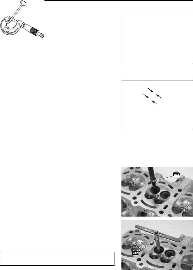
VALVE STEM DEFLECTION
•Lift the valve about 10 mm from the valve seat.
•Measure the valve stem deflection in two directions, perpendicular to each other, by positioning the dial gauge as shown.
•If the deflection measured exceeds the limit, then determine whether the valve or the guide should be replaced with a new one.
Valve stem deflection (IN & EX):
Service Limit: 0.25 mm
09900-20607: Dial gauge (1/100 mm)
09900-20701: Magnetic stand
VALVE STEM WEAR
•If the valve stem is worn down to the limit, as measured with a micrometer, replace the valve.
•If the stem is within the limit, then replace the guide.
• After replacing valve or guide, be sure to recheck the deflec- |
|
|
||
tion. |
|
|
E |
|
Valve stem O.D.: |
|
|
||
|
L |
|||
|
|
|||
Standard (IN) : 4.475 – 4.490 mm (0.1762 – 0.1768 in) |
|
|
||
(EX) : 4.455 – 4.470 mm (0.1754 – 0.1760 in) |
|
|
||
09900-20205: Micrometer (0 – 25 mm) |
P |
|
|
|
|
|
|||
NOTE: |
|
|
|
|
If valve guides have to be removed for replacement after |
|
|
||
|
A |
|
|
|
inspecting related parts, carry out theMsteps shown in valve |
|
|
||
guide servicing. ( below) |
|
|
|
|
S |
|
|
|
|
VALVE GUIDE SERVICING |
|
|
|
|
•Using the valve guide remover, drive the valve guide out toward the intake or exhaust camshaft side.
09916-43211: Valve guide remover/installer
NOTE:
*Discard the removed valve guide subassemblies.
*Only oversized valve guides are available as replacement parts. (Part No. 11115-29G70)
•Re-finish the valve guide holes in cylinder head with the reamer and handle.
09916-33320: Valve guide reamer
09916-34542: Reamer handle
When refinishing or removing the reamer from the valve guide hole, always turn it clockwise.

3-34 ENGINE
• Cool down the new valve guides in a freezer for about one hour and heat the cylinder head to 100 °C – 150 °C (212 °F – 302 °F) with a hot plate.
Do not use a burner to heat the valve guide hole to prevent cylinder head distortion.
•Apply engine oil to the valve guide hole.
•Drive the valve guide into the hole using the valve guide installer 1 and attachment 2.
09916-43211: Valve guide installer/remover
09916-44930: Attachment
09916-53330: Attachment
NOTE: |
|
|
|
|
|
|
|
|
|
|
|
|
|
|
|
|
|
|
|
|
|
Install the valve guide until the attachment 2 contacts with the |
|
|
|
|
|
|
|
|
||
cylinder head 3. |
A: 14.1 mm (0.555 in) (IN) |
|
|
|
|
|
|
|
|
|
|
|
|
|
|
|
|
|
|||
|
|
|
|
|
|
|
|
|||
|
|
|
|
|
|
|
|
|
||
|
|
|
|
|
|
|
|
|
||
|
|
E |
|
|
|
|||||
|
13.2 mm (0.520 in) (EX) |
|
|
|
|
|||||
|
|
|
|
|||||||
|
|
|
|
|
|
|||||
|
|
L |
|
|
|
|
|
|
||
|
|
|
|
|
|
|
||||
Failure to oil the valve guide hole before driving the |
|
|
||||||||
|
|
|
|
|
|
|
|
|
||
new guide into place may result in a damaged guide or |
|
|
|
|
|
|
|
|
|
|
|
P |
|
|
|
||||||
head. |
M |
|
|
|
|
|
|
|
|
|
|
|
|
|
|
|
|
|
|
||
|
|
|
|
|
|
|
|
|
|
|
• After installing the valve guides, re-finish their guiding bores |
|
|
|
|
|
|
|
|
||
using the reamer. |
A |
|
|
|
|
|
|
|
|
|
S |
|
|
|
|
|
|
|
|
||
|
|
|
|
|
|
|
|
|
||
• Clean and oil the guides after reaming. |
|
|
|
|
|
|
|
|
||
09916-33210: Valve guide reamer
09916-34542: Reamer handle
NOTE:
*Be sure to cool down the cylinder head to ambient air temperature.
*Insert the reamer from the combustion chamber and always turn the reamer handle clockwise.
VALVE SEAT WIDTH INSPECTION
•Visually check for valve seat width on each valve face.
•If the valve face has worn abnormally, replace the valve.
•Coat the valve seat with Prussian Blue and set the valve in place. Rotate the valve with light pressure.
•Check that the transferred blue on the valve face is uniform all around and in center of the valve face.
09916-10911: Valve lapper set

ENGINE 3-35
•If the seat width W measured exceeds the standard value or seat width is not uniform, reface the seat using the seat cutter.
Valve seat width W:
Standard: 0.9 – 1.1 mm (0.035 – 0.043 in)
If the valve seat is out of specification, re-cut the seat.
VALVE SEAT SERVICING |
|
|
|
|
|
|
|
|
|
|
|
|
|
|
|
|
|
|
|
|
|
||
• The valve seats 1 for both the intake valve 2 and exhaust |
|
|
|
|
|
|
|
|
|
|
|
|
|
|
|
|
|
|
|
||||
valve 3 are machined to four different angles. The seat con- |
|
|
|
|
|
|
|
|
|
|
|
|
|
|
|
|
|
|
|
||||
|
|
|
|
|
|
|
|
|
|
|
|
|
|
|
|
|
|
|
|||||
tact surface is cut at 45°. |
|
|
|
|
|
|
|
|
|
|
|
|
60˚ |
|
|
|
|
|
|
||||
|
|
|
|
60˚ |
|
||||||||||||||||||
|
|
|
|
|
|
|
|
|
|
|
|
||||||||||||
|
|
|
|
|
|
|
|
|
|
|
|
|
|
|
15˚ |
|
|
||||||
|
|
|
|
|
|
|
|
|
|
|
|
|
|||||||||||
|
|
|
|
|
|
|
|
|
|
|
30˚ |
|
|
|
|
|
|
|
|
|
|||
|
|
|
|
|
|
|
|
|
|
|
|
|
|
|
|
|
|
||||||
|
INTAKE |
|
EXHAUST |
|
|
|
|
|
|
45˚ |
|
|
|
|
|
|
45˚ |
|
|
||||
|
|
|
|
|
|
|
|
|
|
|
|
||||||||||||
|
|
|
|
|
|
|
|
|
|
|
|
|
|
|
|
|
|
|
|
||||
|
|
|
|
|
|
|
|
|
|
|
|
|
|
|
|
|
|
|
|
|
|
|
|
Seat angle |
30°, 45°, 60° |
|
15°, 45°, 60° |
|
|
|
|
|
|
|
|
|
|
|
|
|
|
|
|
|
|
|
|
|
|
|
|
|
|
|
|
|
|
|
|
|
|
|
|
|
|
|
|
|
|||
|
|
|
|
|
|
|
|
|
|
|
|
|
|
|
|
|
|
|
|
|
|||
|
|
|
|
|
|
|
|
|
|
|
|
|
|
|
|
|
|
|
|
|
|
|
|
Seat width |
0.9 – 1.1mm (0.035 – 0.043 in) |
|
|
|
|
|
|
|
|
|
|
|
|
|
|
|
|
|
|
|
|
||
|
|
E |
|
|
|
|
|
|
|
|
|
|
|||||||||||
|
|
|
|
|
|
|
|
|
|
|
|
|
|
|
|||||||||
Valve diameter |
27.2 mm (1.07 in) |
|
22 mm (0.87 in) |
|
|
|
|
|
|
|
|
|
|
|
|
||||||||
|
|
|
|
|
|
|
|
|
|
|
|
|
|
|
|
||||||||
|
|
|
|
|
|
|
|
|
|
|
|
|
|
|
|||||||||
Valve guide I.D. |
4.500 – 4.512 mm (0.177 – 0.178 in) |
|
|
|
|
|
|
|
|
|
|
|
|
|
|
|
|
|
|
|
|
||
|
|
|
|
|
|
|
|
|
|
|
|
|
|
|
|
|
|
|
|
|
|
|
|
|
|
|
P |
|
|
|
|
|
|
|
|
|
|
|
|
|
|
|
|
|
|
|
|
* The valve seat contact area must be inspected afterL |
|
|
|
|
|
|
|
|
|
|
|||||||||||||
each cut. |
M |
|
|
|
|
|
|
|
|
|
|
|
|
|
|
|
|
|
|
|
|||
|
|
|
|
|
|
|
|
|
|
|
|
|
|
|
|
|
|
|
|
||||
* Do not use lapping compound after the final cut is |
|
|
|
|
|
|
|
|
|
|
|
|
|
|
|
|
|
|
|
||||
made. The finished valve seat should have a velvety |
|
|
|
|
|
|
|
|
|
|
|
|
|
|
|
|
|
|
|
||||
|
A |
|
|
|
|
|
|
|
|
|
|
|
|
|
|
|
|
|
|
|
|
|
|
smooth finish but not a highly polished or shiny fin- |
|
|
|
|
|
|
|
|
|
|
|
|
|
|
|
|
|
|
|
||||
ish. This will provide a soft surface for the final seat- |
|
|
|
|
|
|
|
|
|
|
|
|
|
|
|
|
|
|
|
||||
ing of the valve which will occur during the first few |
|
|
|
|
|
|
|
|
|
|
|
|
|
|
|
|
|
|
|
||||
seconds of engineSoperation. |
|
|
|
|
|
|
|
|
|
|
|
|
|
|
|
|
|
|
|
|
|
||
* The titanium valves are coated with an oxidized |
|
|
|
|
|
|
|
|
|
|
|
|
|
|
|
|
|
|
|
||||
membrane treatment to resist wear but the mem- |
|
|
|
|
|
|
|
|
|
|
|
|
|
|
|
|
|
|
|
||||
brane tend to be removed if lapped after valve seat |
|
|
|
|
|
|
|
|
|
|
|
|
|
|
|
|
|
|
|
||||
servicing. |
|
|
|
|
|
|
|
|
|
|
|
|
|
|
|
|
|
|
|
|
|
|
|
|
|
|
|
|
|
|
|
|
|
|
|
|
|
|
|
|
|
|
|
|
|
|
|
NOTE:
After servicing the valve seats, be sure to check the valve clearance after the cylinder head has been reinstalled. ( 2-7)
•Clean and assemble the head and valve components. Fill the intake and exhaust ports with gasoline to check for leaks.
•If any leaks occur, inspect the valve seat and face for burrs or other things that could prevent the valve from sealing.
Always use extreme caution when handling gasoline.

3-36 ENGINE
VALVE SPRING
The force of the coil spring keeps the valve seat tight. Weakened spring result in reduced engine power output, and often account for the chattering noise coming from the valve mechanism.
•Check the valve spring for proper strength by measuring its free length and also by the force required to compress it.
•If the spring length is less than the service limit, or if the force required to compress the spring does not fall within the range specified, replace the spring.
Valve spring free length:
Service limit (IN & EX): 38.2 mm (1.504 in)
09900-20102: Vernier calipers
Valve spring tension (IN & EX):
Standard: 203 – 233 N (20.7 – 23.8 kgf)/33.55 mm (45.6 – 52.4 lbs/1.32 in)
|
|
|
|
|
|
E |
|
|
|
|
|
|
|
|
|
VALVE AND VALVE SPRING REASSEMBLY |
|
|
L |
|
|||
• Install the valve spring seat. |
|
P |
|
||||
|
|
|
|
|
|
||
• Apply MOLYBDENUM OIL SOLUTION to the oil seal 1, and |
|
|
|
||||
press-fit it into position. |
|
M |
|
|
|
||
MOLYBDENUM OIL SOLUTION |
|
|
|
||||
|
A |
|
|
|
|
|
|
|
|
|
|
|
|
|
|
|
|
|
|
|
|
|
|
|
S |
|
|
|
|
|
|
Do not reuse the removed oil seal. |
|
|
|
|
|
|
|
|
|
|
|
|
|
|
|
•Insert the valve, with its stem coated with MOLYBDENUM OIL SOLUTION all around and along the full stem length without any break.
When inserting the valve, take care not to damage the lip of the oil seal.
MOLYBDENUM OIL SOLUTION
•Install the valve spring with the small-pitch portion A facing cylinder head.
B Large-pitch portion
C UPWARD
D Paint

ENGINE 3-37
•Put on the valve spring retainer 2, and using the special tool 3, press down the spring, fit the cotter halves 4 to the stem
end, and release the lifter to allow the cotter halves to wedge in between retainer and stem.
09916-14510: Valve lifter
09916-14530: Valve lifter attachment
09916-84511: Tweezers
09919-28610: Sleeve protector
• Be sure that the rounded lip E of the cotter fits snugly into the groove F in the stem end.
• Install the other valves and springs in the same manner as described previously.
Be sure to restore each spring and valve to their original positions.
|
|
|
|
E |
|
|
|
|
|
|
|
|
|
|
|
|
|
|
|
L |
|||
Be careful not to damage the valve and valve stem |
|
|
|||
when handling it. |
|
P |
|
|
|
|
|
|
|
|
|
|
2 Valve spring retainer |
|
|
||
|
M |
|
|
||
|
4 Cotter |
|
|
|
|
• Install the tappet shims and the tappets to their original posi- |
|
|
|||
tions. |
S |
|
|
|
|
A |
|
|
|
|
|
NOTE:
*Apply engine oil to the stem end, shim and tappet before fitting them.
*When seating the tappet shim, be sure the figure printed surface faces the tappet.
INTAKE PIPE
• Remove the intake pipes.
3-38 ENGINE
• Apply SUZUKI SUPER GREASE “A” to the O-rings.
99000-25010: SUZUKI SUPER GREASE “A”
(or equivalent grease)
•Install the intake pipes.
•Apply THREAD LOCK to the bolts.
99000-32050: THREAD LOCK “1342”
CLUTCH
CLUTCH DRIVE PLATE INSPECTION
NOTE:
*Wipe off engine oil from the clutch drive plates with a clean rag.
*Clutch drive plate No.1: I.D. 111 mm (4.4 in)/Purple paint
*Clutch drive plate No.2: I.D. 111 mm (4.4 in)/Black paint
*Clutch drive plate No.3: I.D. 118 mm (4.6 in)/NIL
|
A Paint |
|
|
|
|
L |
|||
• Measure the thickness of drive plates with a vernier calipers. |
||||
|
E |
|||
|
P |
|||
• If the drive plate thickness is found to have reached the limit, |
|
|
||
replace it with a new one. |
M |
|
|
|
Drive plate thickness: |
|
|
||
|
|
|
||
Service Limit: 2.42 mm (0.095 in) |
|
|
|
|
A |
|
|
||
09900-20102: Vernier calipers |
|
|
|
|
S |
|
|
|
|
• Measure the claw width of drive plates with a vernier calipers. |
|
|
||
• Replace the drive plates found to have worn down to the limit. |
|
|
||
Drive plate claw width: |
|
|
|
|
Service Limit: 13.05 mm (0.5138 in) |
|
|
|
|
09900-20102: Vernier calipers |
|
|
|
|
|
|
|
|
|
CLUTCH DRIVEN PLATE INSPECTION
NOTE:
Wipe off engine oil from the clutch driven plates with a clean rag.
•Measure each driven plate for distortion with a thickness gauge and surface plate.
•Replace driven plates which exceed the limit.
Driven plate distortion (No. 1 and No. 2):
Service Limit: 0.10 mm (0.004 in)
09900-20803: Thickness gauge

ENGINE 3-39
CLUTCH SPRING INSPECTION
•Measure the free length of each coil spring with a vernier calipers, and compare the length with the specified limit.
•Replace all the springs if any spring is not within the limit.
Clutch spring free length:
Service Limit: 53.2 mm (2.094 in)
09900-20102: Vernier calipers
CLUTCH BEARING INSPECTION
•Inspect the clutch release bearing for any abnormality, particularly cracks, to decide whether it can be reused or should be replaced.
•Smooth engagement and disengagement of the clutch depends on the condition of this bearing.
|
|
E |
|
L |
|
CLUTCH SLEEVE HUB/PRIMARY DRIVEN GEAR ASSEMB Y |
|
|
• Inspect the slot of the clutch sleeve hub and primary driven |
|
|
|
P |
|
gear assembly for damage or wear caused by the clutch |
|
|
plates. If necessary, replace it with a new one. |
|
|
M |
|
|
A |
|
|
S |
|
|
CLUTCH LIFTER
CLUTCH LIFTER DRIVE CAM AND DRIVEN CAM INSPEC-
TION
•Inspect the clutch lifter drive cam and driven cam for wear or damage.
•If any defects are found, replace the clutch lifter drive cam or driven cam.
3-40 ENGINE
CLUTCH LIFTER PIN ADJUSTMENT
NOTE:
When adjusting the clutch lifter, it is not necessary to install the clutch onto the countershaft.
• Assemble the following parts into the primary driven gear assembly. ( 3-85 to -88)
*Clutch sleeve hub
*Spring washer seat, Spring washer
*Clutch drive plates, Clutch driven plates
*Pressure plate
*Clutch springs, Clutch springs set bolts
Clutch spring set bolt: 10 N·m (1.0 kgf-m, 7.0 lb-ft)
•Remove the clutch assembly from the primary driven gear assembly.
|
|
E |
|
L |
|
|
P |
|
|
M |
|
• Check the height H of clutch lifter adjusting pin screws at |
|
|
three positions using the thickness gauge. |
|
|
• If the measurement is out of the specification, adjust the |
|
|
height H as shown in the followingAspecification. |
|
|
Clutch lifter adjustingSpin screw height H |
|
|
Standard: 0.2 – 0.4 mm (0.008 – 0.016 in) |
|
|
09900-20803: Thickness gauge |
|
|
NOTE: |
|
|
Each clutch lifter adjusting pin screw height should be as closely |
|
|
|
||
as possible. |
|
|
•Loosen the lock-nut and turn out the adjusting pin screw.
•Set the thickness gauge to 0.3 mm (0.012 in).
•Place a proper flat plate on the thickness gauges and hold them by hand.
•Slowly turn in the adjusting pin screw until resistance is felt.
•Tighten the lock-nut.
Clutch lifter pin lock-nut: 23 N·m (2.3 kgf-m, 16.5 lb-ft)

ENGINE 3-41
WAVE SPRING WASHER INSPECTION
•Measure the free height H of each wave spring washer with a vernier calipers.
•If each wave spring washer height H is not within the specified limit, replace it with a new one.
09900-20102: Vernier calipers
Wave spring washer height H
Service Limit: 4.30 mm (0.169 in)
OIL PUMP
INSPECTION
• Remove the oil pump driven sprocket 1.
|
|
|
E |
|
L |
||
• Rotate the oil pump shaft by hand and check that it moves |
|
||
|
P |
|
|
smoothly. |
|
|
|
• If it does not move smoothly, replace the oil pump assembly. |
|
||
|
M |
|
|
|
|
|
|
|
A |
|
|
* Do not attempt to disassemble the oil pump assembly. |
|
|
|
* The oil pump is available only as an assembly. |
|
|
|
|
S |
|
|
STARTER CLUTCH
INSPECTION
•Install the starter driven gear onto the starter clutch and turn the starter driven gear by hand to inspect the starter clutch for a smooth movement. The gear turns one direction only. If a large resistance is felt to rotation, inspect the starter clutch for damage or inspect the starter clutch contacting surface of the starter driven gear for wear or damage.
•If they are found to be damaged, replace them with new ones.
•Inspect the starter driven gear bearing for any damages.

3-42 ENGINE
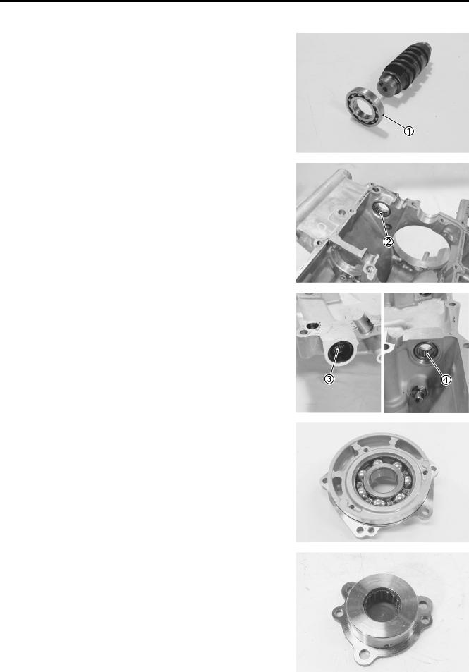
DISASSEMBLY
•With holding the rotor with the special tool remove the starter clutch bolts.
09930-44520: Rotor holder
• Remove the one way clutch 1 and guide 2 from the rotor.
|
|
|
E |
REASSEMBLY |
|
L |
|
|
|
|
|
• When fitting the one way clutch 1 to the guide 2, position |
|
||
flange side A of one way clutch to the rotor side. |
P |
|
|
|
M |
|
|
|
A |
|
|
|
S |
|
|
•When installing the starter clutch guide 2 to the rotor 3, make sure that the flange B side faces outside.
•Degrease the securing bolts and bolt holes.
•Apply THREAD LOCK SUPER “1303” to the bolts and tighten them to the specified torque while holding the rotor with the special tool.
99000-32030: THREAD LOCK SUPER “1303”
Starter clutch securing bolt: 10 N·m (1.0 kgf-m, 7.0 lb-ft)
09930-44520: Rotor holder

ENGINE 3-43
GENERATOR
INSPECTION ( 9-10)
REASSEMBLY
• When installing the generator stator set bolts, tighten them to the specified torque.
Generator stator set bolt: 11 N·m (1.1 kgf-m, 8.0 lb-ft)
NOTE:
Be sure to install the grommet 1 to the generator cover.
WATER PUMP
7-11
GEARSHIFT SYSTEM
GEARSHIFT SHAFT/GEARSHIFT ARM DISASSEMBLY
• Remove the following parts from the gearshift shaft/gearshift
|
arm. |
|
|
|
|
1 |
Washer |
5 |
Plate return spring |
E |
|
2 |
Snap ring |
6 |
Washer |
||
L |
|||||
3 |
Gearshift shaft return spring |
7 |
Screw |
||
|
|||||
4 |
Gearshift cam drive plate |
|
|
|
GEARSHIFT SHAFT/GEARSHIFT ARM INSPECTIONP
• Inspect the gearshift shaft/gearshift armMfor wear or bend.
• Inspect the return springs for damage or fatigue.
• Replace the arm or spring ifAthere is anything unusual.
GEARSHIFT SHAFT/GEARSHIFT ARM REASSEMBLY
• Apply THREAD LOCK to the gearshift shaft screw.
99000-32050: THREAD LOCK “1342”
NOTE:
When installing the gearshift shaft return spring, position the stopper A of gearshift arm between the shaft return spring ends
B.

3-44 ENGINE
• Install the following parts to the gearshift shaft/gearshift arm as shown in the illustration.
1 |
Washer |
5 |
Plate return spring |
2 |
Snap ring |
6 |
Washer |
3 |
Gearshift shaft return spring |
7 |
Screw |
4 |
Gearshift cam drive plate |
|
|
|
|
|
E |
|
|
|
|
L |
|
|
|
|
|
|
OIL PRESSURE REGULATOR |
P |
|||
|
|
|
||
• Inspect the operation of the oil pressure regulator by pushing |
||||
on the piston with a proper bar. |
|
M |
||
|
|
|
||
• If the piston does not operate, replace the oil pressure regula- |
||||
tor with a new one. |
|
A |
||
|
|
|||
|
S |
|
|
|
OIL STRAINER
•Inspect the oil strainer body for damage.
•Clean the oil strainer if necessary.

ENGINE 3-45
TRANSMISSION
DRIVESHAFT REMOVAL ( 3-51)
DISASSEMBLY
Disassemble the countershaft and driveshaft. Pay attention to the following points:
• Remove the 6th drive gear snap ring 1 from its groove and slide it towards the 3rd/4th drive gears 2.
•Slide the 6th 3 and 2nd 4 drive gears toward the 3rd/4th drive gears 2, then remove the 2nd drive gear circlip 5.
 E
E
L
P
M
A
S
1 |
Countershaft/1st drive gear |
8 |
6th driven gear |
|
|
|
|
2 |
5th drive gear |
9 |
3rd driven gear |
|
|
|
|
3 |
3rd/4th drive gears |
0 |
4th driven gear |
|
|
|
|
4 |
6th drive gear |
A |
5th driven gear |
|
|
|
|
5 |
2nd drive gear |
B |
1st driven gear |
|
|
|
|
6 |
Driveshaft |
A |
Engine sprocket nut |
7 |
2nd driven gear |
|
|
ITEM |
N·m |
kgf-m |
lb-ft |
|
|
|
|
A |
115 |
11.5 |
83.2 |
3-46 ENGINE
REASSEMBLY
Assemble the countershaft and driveshaft in the reverse order of disassembly. Pay attention to the following points:
NOTE:
*Rotate the bearings by hand to inspect for smooth rotation. Replace the bearings if there is anything unusual.
*Before installing the gears, apply engine oil to the driveshaft and countershaft.
*When installing the oil seal, apply SUZUKI SUPER GREASE “A” to it.
99000-25010: SUZUKI SUPER GREASE “A”
(or equivalent grease)
* Never reuse a snap ring. After a snap ring has been |
|
|
|
||
removed from a shaft, it should be discarded and a |
|
|
|
||
new snap ring must be installed. |
|
|
|
|
|
* When installing a new snap ring, do not expand the |
|
|
|
||
end gap larger than required to slip the snap ring |
|
L |
|||
over the shaft. |
|
|
|
||
* After installing a snap ring, make sure that it is com- |
|
||||
|
|
E |
|||
pletely seated in its groove and securely fitted. |
P |
||||
|
|
|
|
||
|
|
|
|
|
|
NOTE: |
M |
|
|
||
|
|
|
|||
When reassembling the transmission, attention must be given to |
|
|
|||
the locations and positions of washers and snap rings. The |
|
|
|||
cross sectional view shows the correct position of the gears, |
|
|
|||
bushings, washers and snap rings. (A3-47) |
|
|
|
|
|
• When installing a new snapSring, pay attention to its direction. |
|
|
|||
|
|
||||
Fit it to the side where the thrust is as shown in the illustration. |
|
|
|||
|
A Thrust |
|
|
||
|
B Sharp edge |
|
|
||
|
|
|
|
|
|
|
|
|
|
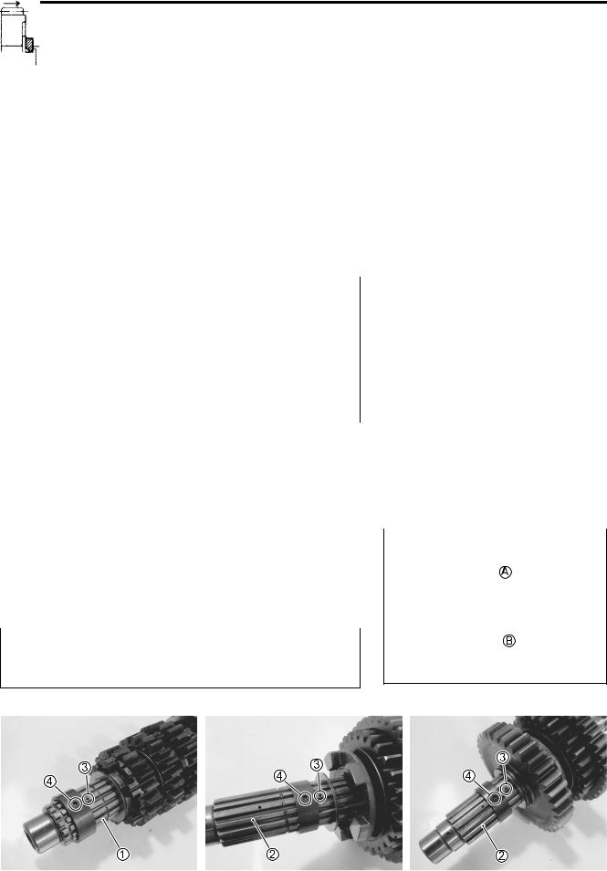
|
|
When installing the gear bushing onto the countershaft 1 and driveshaft 2, align the shaft oil hole 3 with the bushing oil hole 4.

ENGINE 3-47
TRANSMISSION PARTS LOCATION
E
L
P
M
A
S
1 |
Countershaft |
2 |
Driveshaft |
|
|
|
|
3-48 ENGINE
CYLINDER
CRANKCASE SERVICING ( 3-51)
CYLINDER DISTORTION
•Check the gasketed surface of the cylinder for distortion with a straightedge and thickness gauge, taking a clearance reading at several places as indicated.
•If the largest reading at any position of the straightedge exceeds the limit, replace the crankcase set.
Cylinder distortion:
Service Limit: 0.02 mm (0.008 in)
09900-20803: Thickness gauge
CYLINDER BORE
•Inspect the cylinder wall for any scratches, nicks or other damage.
•Measure the cylinder bore diameter at six places.
Cylinder bore: |
|
E |
|
Standard: 67.000 – 67.015 mm (2.6378 – 2.6384 in) |
|
||
L |
|||
09900-20508: Cylinder gauge set |
|||
P |
|
||
|
|||
|
|||
M |
|
|
|
A |
|
|
|
S |
|
|
|
|
|
|
|
ENGINE 3-49
PISTON AND PISTON RING
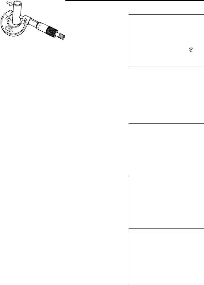
PISTON DIAMETER
•Using a micrometer, measure the piston outside diameter at 15 mm (0.6 in) A from the piston skirt end.
•If the measurement is less than the limit, replace the piston.
Piston diameter:
Service Limit: 66.88 mm (2.6331 in)
at 15 mm (0.6 in) from the skirt end
09900-20203: Micrometer (50 – 75 mm)
|
|
|
|
|
E |
|
|
|
|
|
|
||
PISTON-TO-CYLINDER CLEARANCE |
L |
|||||
• Subtract the piston diameter from the cylinder bore diameter. |
|
|
|
|
||
( 3-48) |
P |
|
|
|
|
|
|
|
|
|
|
|
|
• If the piston-to-cylinder clearance exceeds the service limit, |
|
|
|
|
||
replace the crankcase set or the piston, or both. |
|
|
|
|
|
|
A |
|
|
|
|
|
|
Piston-to-cylinder clearance: |
M |
|
|
|
|
|
Service Limit: 0.120 mm (0.0047 in) |
|
|
|
|
|
|
S |
|
|
|
|
|
|
|
|
|
|
|
|
|
PISTON PIN AND PIN BORE |
|
|
|
|
|
|
•Measure the piston pin bore diameter using the small bore gauge.
•If the measurement is out of specification, replace the piston.
Piston pin bore I.D.:
Service Limit: 14.030 mm (0.5524 in)
09900-20602: Dial gauge (1/1000 mm) 09900-22401: Small bore gauge (10 – 18 mm)
•Measure the piston pin outside diameter at three positions using the micrometer.
•If any of the measurements is out of specification, replace the piston pin.
Piston pin O.D.:
Service Limit: 13.980 mm (0.5503 in)
09900-20205: Micrometer (0 – 25 mm)

3-50 ENGINE
PISTON RING-TO-GROOVE CLEARANCE
•Measure the side clearances of the 1st and 2nd piston rings using the thickness gauge.
•If any of the clearances exceeds the limit, replace both the piston and piston rings.
09900-20803: Thickness gauge
09900-20205: Micrometer (0 – 25 mm)
Piston ring-to-groove clearance: |
||||
Service Limit (1st) : 0.180 mm (0.0071 in) |
|
|
|
|
|
|
|
||
(2nd) : 0.150 mm (0.0059 in) |
||||
Piston ring groove width: |
|
|
|
|
|
|
|
||
Standard (1st) |
: 1.01 – 1.03 mm (0.0398 – 0.0406 in) |
|
|
|
(2nd) : 0.81 – 0.83 mm (0.0319 – 0.0327 in) |
|
|
|
|
(Oil) |
: 1.51 – 1.53 mm (0.0594 – 0.0602 in) |
|
|
|
Piston ring thickness: |
|
|
|
|
Standard (1st) |
: 0.97 – 0.99 mm (0.0382 – 0.0390 in) |
|
|
|
(2nd) : 0.77 – 0.79 mm (0.0303 – 0.0311 in) |
|
E |
|
|
pers. |
GAP |
|
|
|
|
|
|||
PISTON RING FREE END GAP AND PISTON RING END |
|
|
|
|
• Measure the piston ring free end gap using the vernier cali- L |
|
|||
|
M |
|
||
|
A |
|
||
|
S |
|
|
|
•Next, fit the piston ring squarely into the cylinder and measure the piston ring end gap using the thickness gauge.
•If any of the measurements exceeds the service limit, replace the piston ring with a new one.
Piston ring free end gap:
Service Limit (1st) : 4.4 mm (0.17 in) (2nd) : 6.8 mm (0.27 in)
09900-20102: Vernier calipers
Piston ring end gap:
Service Limit (1st) : 0.50 mm (0.020 in) (2nd) : 0.50 mm (0.020 in)
09900-20803: Thickness gauge

ENGINE 3-51
CRANKCASE
DRIVESHAFT AND GEARSHIFT CAM Removal
• Remove the screws.
• Remove the gearshift fork shaft 1, gearshift cam 2 and gearshift forks 3.
•Remove the spacer 4.
•Remove the driveshaft left bearing dust seal 5.
|
|
|
E |
• Remove the driveshaft left bearing case bolts. |
L |
||
|
P |
|
|
• By using suitable size bolts A, remove the driveshaft left |
|
||
bearing case 6. |
M |
|
|
|
|
|
|
|
A |
|
|
|
S |
|
|
• Remove the dowel pin.
•Remove the driveshaft right bearing case bolts.
•By using suitable size bolts A, remove the driveshaft right bearing assembly 7.

3-52 ENGINE
• Remove the driveshaft assembly 8.
GEARSHIFT FORK-TO-GROOVE CLEARANCE
•Using a thickness gauge, check the gearshift fork clearance in the groove of its gear.
•The clearance for each gearshift fork plays an important role in the smoothness and positiveness of the shifting action.
Shift fork-to-groove clearance: |
|
|
|
|
Service Limit: 0.5 mm (0.02 in) |
|
|
|
|
09900-20803: Thickness gauge |
|
|
|
|
• If the clearance checked is noted to exceed the limit specified, |
|
|
||
|
E |
|||
replace the fork or its gear, or both. |
|
|
||
|
|
|
L |
|
GEARSHIFT FORK GROOVE WIDTH |
P |
|
||
|
|
|
||
• Measure the gearshift fork groove width using the vernier cali- |
|
|
||
pers. |
A |
|
|
|
Shift fork groove width: |
|
|
||
|
M |
|
|
|
S |
|
|
|
|
Standard: 5.0 – 5.1 mm (0.197 – 0.201 in) |
|
|
||
09900-20102: Vernier calipers |
|
|
|
|
|
|
|
|
|
GEARSHIFT FORK THICKNESS
•Measure the gearshift fork thickness using the vernier calipers.
Shift fork thickness:
Standard: 4.8 – 4.9 mm (0.189 – 0.193 in)
09900-20102: Vernier calipers
ENGINE 3-53
BEARING AND DUST SEAL
Inspection
•Inspect the gearshift cam bearing 1 for abnormal noise and smooth rotation.
•Replace the bearings if there is anything unusual.
•Inspect the gearshift cam bearing 2, gearshift shaft bearings 3 (LH) and 4 (RH) for abnormal noise and smooth rotation while they are in the crankcase.
•Replace the bearing if there is anything unusual.
E |
L |
P |
M |
A |
S |
•Inspect the driveshaft left bearing for abnormal noise and smooth rotation while it is in the case.
•Replace the bearing if there is anything unusual.
•Inspect the driveshaft right bearing for abnormal noise and smooth rotation.
•If there is anything unusual, replace the bearing assembly.
3-54 ENGINE
•Inspect the driveshaft left bearing dust seal for wear and damage.
•Replace the dust seal if there is anything unusual.
Removal
• Remove the gearshift cam bearing with the special tools.
09923-74511: Bearing remover
09930-30104: Sliding shaft
Be careful not to lean the bearing remover.
|
|
|
|
|
E |
||
• Remove the oil seal. (LH only) |
L |
||
|
P |
||
|
M |
||
|
A |
||
S |
|||
• Remove the gearshift shaft bearings with the special tool.
09921-20240: Bearing remover set (15 mm)
• Remove the bearing with the special tool.
09913-70210: Bearing installer set ( 62)

ENGINE 3-55
• Remove the driveshaft left bearing dust seal from the retainer using the special tool.
09913-50121: Oil seal remover
Installation
• Install the bearings with the special tool.
09913-70210: Bearing installer set (1 32) (2, 3 20)
NOTE:
The stamped mark side of the gearshift shaft bearing faces outside.
E |
L |
P |
M |
A |
S |
• Install new oil seal with the special tool.
09913-70210: Bearing installer set ( 22)
• Apply SUZUKI SUPER GREASE “A” to the oil seal lip.
99000-25010: SUZUKI SUPER GREASE “A”
(or equivalent grease)
• Install the bearing with the special tool.
09913-70210: Bearing installer set ( 68)
NOTE:
The stamped mark side of the driveshaft left bearing faces out-
side.

3-56 ENGINE
• Install the driveshaft left bearing dust seal with the special tool.
09913-70210: Bearing installer set ( 62)
• Put the driveshaft assembly 1 into the lower crankcase.
• Install the driveshaft right bearing assembly 2.
• Apply THREAD LOCK to the bolts and tighten them to the specified torque.
99000-32050: THREAD LOCK “1342”
Driveshaft right bearing case bolt:
12 N·m (1.2 kgf-m, 8.7 lb-ft)
|
|
|
|
|
|
E |
|
• Install the gearshift forks 3 as shown. |
L |
||
|
P |
||
|
M |
||
A |
|||
S |
|
|
|
•Install the gearshift cam 4 with the bearing fitted.
•With engaging each fork end to the cam groove, insert the fork shaft 5.
•Apply THREAD LOCK to the screws and tighten them to the specified torque.
99000-32050: THREAD LOCK “1342”
Bearing retainer screw: 10 N·m (1.0 kgf-m, 7.0 lb-ft)
•Install the dowel pin.
•Apply SUZUKI SUPER GREASE “A” to the O-ring and fit the driveshaft left bearing case 6.
Replace the O-ring with a new one.
99000-25010: SUZUKI SUPER GREASE “A”
(or equivalent grease)

ENGINE 3-57
• Apply THREAD LOCK to the bolts and tighten them to the specified torque.
99000-32050: THREAD LOCK “1342”
Driveshaft left bearing case bolt:
12 N·m (1.2 kgf-m, 8.7 lb-ft)
• Apply SUZUKI SUPER GREASE “A” to the dust seal lip and O-ring.
• Apply THREAD LOCK to the bolts and tighten them to the specified torque.
99000-25010: SUZUKI SUPER GREASE “A”
(or equivalent grease)
99000-32050: THREAD LOCK “1342”
Driveshaft retainer bolt: 12 N·m (1.2 kgf-m, 8.7 lb-ft) |
E |
|||||
|
||||||
|
|
|
L |
|||
|
Replace the O-ring with a new one. |
|
||||
|
|
|||||
|
|
|
|
|
||
|
|
|
|
|
|
|
|
|
|
P |
|
||
|
|
M |
|
|
|
|
|
• Apply SUZUKI SUPER GREASE “A” to the O-ring. |
|
|
|
||
|
A |
|
|
|
||
99000-25010: SUZUKI SUPER GRE SE “A” |
|
|
|
|||
|
|
S |
(or equivalent grease) |
|
||
|
|
|
|
|
|
|
|
|
|
|
|
|
|
|
Replace the O-ring with a new one. |
|
|
|
|
|
|
|
|
|
|
|
|
• Install the spacer 7.
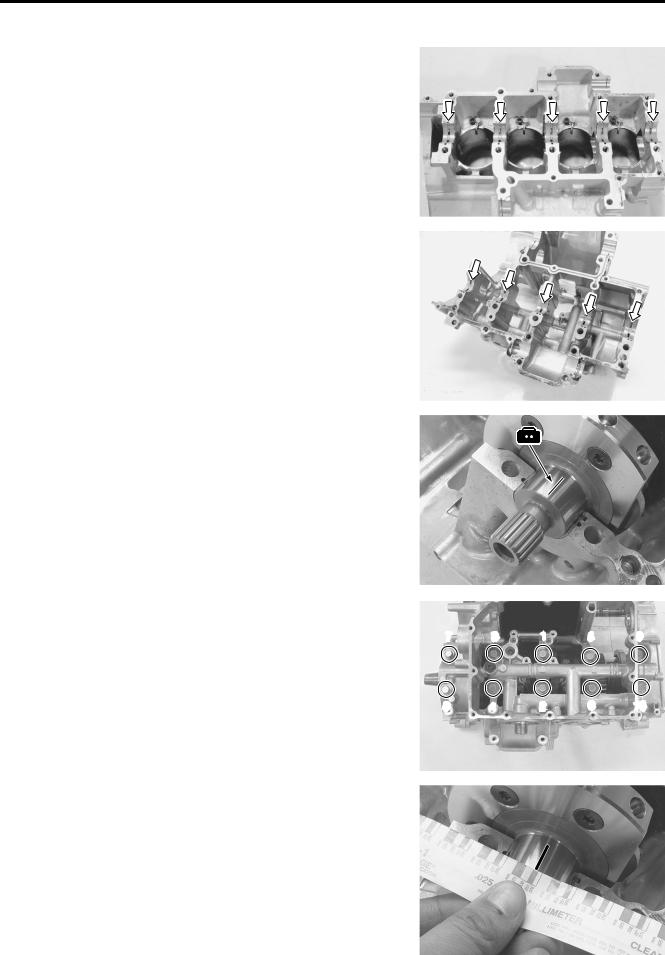
OIL JET
Removal
•Remove the piston cooling oil jets 1 from the upper crankcase.
3-58 ENGINE
•Remove the oil jet 2 (for transmission) from the lower crankcase.
• Remove the oil jet 3 (for cam chain tension adjuster) from the cylinder head.
|
|
E |
Inspection and cleaning |
|
L |
• Check the oil jets for clogging. |
P |
|
• If they are clogged, clean their oil passage with a proper wire |
|
|
and compressed air. |
M |
|
1 Piston cooling oil jet |
|
|
S |
|
|
2 Oil jet (#14) (ForAtransmission) |
|
|
3 Oil jet (#8) (For cam chain tension adjuster)
Installation
•Fit new O-ring 1 to each piston cooling oil jet as shown and apply engine oil to them.
Use new O-rings to prevent oil pressure leakage.
• Install each piston cooling oil jet.
NOTE:
Apply a small quantity of THREAD LOCK to the bolts and tighten them to the specified torque.
99000-32050: THREAD LOCK “1342”
Piston cooling oil jet bolt: 10 N·m (1.0 kgf-m, 7.0 lb-ft)

ENGINE 3-59
• Install the oil jet (for transmission).
• Apply engine oil to the O-ring.
• Install the oil jet (for cam chain tension adjuster).
PLUG |
E |
|
|
||
|
||
P |
|
|
Removal |
|
|
• Remove the oil gallery plugs 1 and 2. |
|
|
L |
|
|
M |
|
|
A |
|
|
S |
|
|
• Remove the oil gallery plugs 3 and 4.
• Remove the water jacket plugs 5 and 6.

3-60 ENGINE
Installation
• Apply THREAD LOCK to the oil gallery plug 2.
99000-32050: THREAD LOCK “1342”
NOTE:
* It is not required to apply THREAD LOCK when installing the other removed oil gallery plugs.
* After tightening the plug 2, make sure that the plug end is flush with the cover mating surface.
•Apply engine coolant to the O-rings of the water jacket plugs 5 and 6.
99000-99032-11X: SUZUKI COOLANT (Except USA)
• Tighten each plug to the specified torque. |
|
|
1 Oil gallery plug: 10 |
N·m (1.0 kgf-m, |
7.0 lb-ft) |
2 Oil gallery plug: 22 |
N·m (2.2 kgf-m, |
16.0 lb-ft) |
3 Oil gallery plug: 15 |
N·m (1.5 kgf-m, |
11.0 lb-ft) |
4 Oil gallery plug: 35 |
N·m (3.5 kgf-m, |
25.5 lb-ft) |
|
|
E |
5 Water jacket plug: 9.5 N·m (0.95 kgf-m, 6.9 lb-ft) |
|
|
6 Water jacket plug: 9.5 N·m (0.95 kgf-m, 6.9 lb-ft) |
|
|
|
|
|
|
P |
|
Use new gasket or O-ring for each plug. |
|
L |
|
M |
|
A |
|
|
S |
|
|
ENGINE 3-61
09900-20607: Dial gauge (1/100 mm, 10 mm)
09900-20701: Magnetic stand
09900-21304: V-block set (100 mm)
CONROD SMALL END I.D. |
|
|
|
|
|
|
|
|
• Using a small bore gauge, measure the inside diameter of the |
|
|
|
|
|
|||
conrod small end. |
|
|
|
|
|
|
|
|
Conrod small end I.D.: |
|
|
|
E |
|
|
||
Service Limit: 14.040 mm (0.5528 in) |
|
|
|
|
||||
09900-20602: Dial gauge (1/1000 mm, 1 mm) |
|
|
|
|
||||
09900-22401: Small bore gauge (10 – 18 mm) |
|
|
|
|
||||
L |
|
|
|
|||||
|
|
|
|
|
|
|||
|
|
|
|
|
|
|||
• If the inside diameter of the conrod small end exceeds the |
|
|
|
|
|
|||
limit, replace the conrod. |
P |
|
|
|
|
|
||
|
|
|
|
|
||||
|
|
|
|
|
||||
|
|
|
|
|
|
|
||
CONROD BIG END SIDE CLE R NCE |
|
|
|
|
|
|
||
|
|
M |
|
|
|
|
|
|
• Inspect the conrod side clearance by using a thickness |
|
|
|
|
|
|||
gauge. |
|
A |
|
|
|
|
|
|
• If the clearance exceeds the limit, remove the conrod and |
|
|
|
|
|
|||
|
S |
|
|
|
|
|
|
|
inspect the conrod big end width and the crank pin width. |
|
|
|
|
|
|||
• If the width exceed the limit, replace conrod or crankshaft. |
|
|
|
|
|
|||
Conrod big end side clearance:
Service Limit: 0.30 mm (0.012 in)
09900-20803: Thickness gauge
Conrod big end width:
Standard: 19.95 – 20.00 mm (0.7854 – 0.7874 in)
09900-20205: Micrometer (0 – 25 mm)
Crank pin width:
Standard: 20.10 – 20.15 mm (0.7913 – 0.7933 in)
09900-20605: Dial calipers (1/100 mm, 10 – 34 mm)

3-62 ENGINE
CONROD-BIG END BEARING INSPECTION
•Inspect the bearing surfaces for any sign of fusion, pitting, burn, or flaws. If any, replace them with a specified set of bearings.
CONROD-BIG END BEARING SELECTION
•Place the plastigauge axially along the crank pin, avoiding the oil hole, as shown.
09900-22301: Plastigauge
•Tighten the conrod cap bolts to the specified torque, in two stages. ( 3-73)
* Apply engine oil to the bearing cap bolt. |
|
|
|
|
* Never rotate the crankshaft or conrod when a piece |
LE |
|||
of plastigauge is installed. |
|
|
||
|
|
P |
|
|
|
|
|
||
*1: The number faces the intake side. |
M |
|
|
|
|
|
|
|
|
A |
|
|
|
|
S |
|
|
|
|
|
|
|
|
*1 |
|
|
|
|
|
•Remove the bearing caps and measure the width of the compressed plastigauge using the envelope scale. This measurement should be taken at the widest part of the compressed plastigauge.
Conrod big end oil clearance:
Standard: 0.032 – 0.056 mm (0.0013 – 0.0022 in) Service Limit: 0.080 mm (0.0031 in)
•If the oil clearance exceeds the service limit, select the specified bearings from the bearing selection table.
ENGINE 3-63
•Check the corresponding conrod I.D. code number (“1” or “2”)
A.
•Check the corresponding crank pin O.D. code number (“1”, “2” or “3”) B.
Bearing selection table
|
|
|
Crank pin O.D. B |
|
|
|
|||
|
Code |
1 |
|
2 |
|
3 |
|
|
|
Conrod |
1 |
Green |
|
Black |
|
Brown |
|
||
I.D A |
|
|
|
|
|
|
|
|
|
2 |
Black |
|
Brown |
|
Yellow |
E |
|||
Conrod I.D. |
|
|
|
|
|
|
|
||
|
|
|
|
|
|
|
|
||
|
|
|
|
|
|
|
|
|
|
|
1 |
|
|
|
I.D. specification |
L |
|||
|
Code |
|
|
|
|
|
|||
|
|
|
|
34.000 – 34.008 mm |
|
|
|||
|
|
|
|
(1.3386 – 1.3389 in) |
|
|
|||
|
|
|
|
|
|
|
|
||
|
|
|
|
|
M |
|
|
||
|
2 |
|
|
34.008 – 34.016Pmm |
|
||||
|
|
|
(1.3389 – 1.3392 in) |
|
|
||||
|
|
|
|
|
|
||||
|
|
|
A |
|
|
|
|||
|
S |
|
|
|
|
|
|
||

3-64 ENGINE
Crank pin O.D.
Code |
O.D. specification |
1 |
30.992 – |
31.000 mm |
|
|
(1.2202 – 1.2205 in) |
|
|||
|
|
|||
2 |
30.984 – |
30.992 mm |
|
|
(1.2198 – 1.2202 in) |
|
|||
|
|
|||
3 |
30.976 – |
30.984 mm |
|
|
(1.2195 – 1.2198 in) |
|
|||
|
|
|||
09900-20202: Micrometer (25 – 50 mm) |
|
|
||
Bearing thickness |
|
|
|
|
Color C (Part No.) |
Thickness |
|
||
Yellow |
1.492 – |
1.496 mm |
|
|
(12164-29G00-0D0) |
(0.0587 – 0.0589 in) |
|
||
Brown |
1.488 – |
1.492 mm |
|
|
(12164-29G00-0C0) |
(0.0586 – 0.0587 in) |
|
||
Black |
1.484 – |
1.488 mm |
E |
|
(12164-29G00-0B0) |
(0.0584 – 0.0586 in) |
|||
Green |
1.480 – |
1.484 mm |
||
(12164-29G00-0A0) |
(0.0583 – 0.0584 in) |
|||
L |
||||
|
|
|
||
|
P |
|||
The bearings must be replaced as a set. |
||||
|
M |
|
||
|
A |
|
||
|
S |
|
|
|
ENGINE 3-65
CRANKSHAFT JOURNAL BEARING
INSPECTION
• Inspect each bearing of upper and lower crankcases for any damage.
|
|
|
|
E |
|
|
|
|
|
|
|
SELECTION |
|
|
L |
|
|
• Place the plastigauge axially along the crankshaft journal, |
|
||||
|
|||||
avoiding the oil hole, as shown. |
M |
|
|||
09900-22301: Plastigauge |
|
||||
P |
|
||||
|
|
|
|
|
|
|
|
A |
|
|
|
Never rotate the crankshaft when a piece of plasti- |
|
|
|||
|
S |
|
|
|
|
gauge is installed. |
|
|
|
|
|
•Mate the lower crankcase with the upper crankcase.
•Tighten the crankshaft journal bolts (M9) in ascending order of numbers assigned to these bolts. Tighten each bolt a little at a time to equalize the pressure.
Crankshaft journal bolt: (M9)
Initial : 18 N·m (1.8 kgf-m, 13.0 lb-ft) Final : 50°
•Remove the lower crankcase and measure the width of the compressed plastigauge using the envelope scale. This measurement should be taken at the widest part of the compressed plastigauge.
Crankshaft journal oil clearance:
Standard: 0.010 – 0.028 mm (0.0004 – 0.0011 in) Service Limit: 0.080 mm (0.0031 in)
•If the oil clearance exceeds the service limit, select the specified bearings from the bearing selection table.
7 |
3 |
1 |
5 |
9 |
8 |
4 |
2 |
6 |
10 |

3-66 ENGINE
•Check the corresponding crankcase journal I.D. code number A, “A”, “B” or “C” which is stamped on the rear of upper
crankcase.
•Check the corresponding crankshaft journal O.D. code number B, “A”, “B” or “C” which is stamped on the crankshaft.
Bearing selection table
|
|
Crankshaft journal O.D. B |
|||
|
Code |
A |
B |
C |
|
Crankcase |
A |
Green |
Black |
Brown |
|
B |
Black |
Brown |
Yellow |
||
I.D. A |
|||||
|
|
|
|
||
C |
Brown |
Yellow |
Blue |
||
|
|||||
Crankcase I.D. specification
Code |
|
I.D. specification |
|
|
|
|
|
A |
|
33.000 – 33.006 mm |
|
|
(1.29921 – 1.29945 in) |
|
|
|
|
|
|
|
|
|
E |
B |
|
33.007 – 33.012 mm |
|
|
(1.29949 – 1.29968 in) |
||
|
|
||
|
|
L |
|
|
|
|
|
C |
|
33.013 – 33.018 mm |
|
|
|
||
|
(1.29972 – 1.29992 in) |
|
|
|
|
|
|
|
|
|
|
|
|
P |
|
|
|
M |
|
|
|
A |
|
|
S |
|
|

ENGINE 3-67
Crankshaft journal O.D. specification
Code |
O.D. specification |
A
29.994 – 30.000 mm
(1.18086 – 1.18110 in)
B
29.988 – 29.994 mm
(1.18062 – 1.18086 in)
C
29.982 – 29.988 mm
(1.18039 – 1.18062 in)
09900-20202: Micrometer (25 – 50 mm)
Bearing thickness specification |
|
|
||
|
|
|
|
|
Color (Part No.) |
|
Thickness |
|
|
|
|
|
|
|
Blue |
|
1.504 – 1.507 mm |
|
|
(12229-01H00-0E0) |
|
(0.0592 – 0.0593 in) |
|
|
|
|
|
|
|
Yellow |
|
1.501 – 1.504 mm |
|
|
(12229-01H00-0D0) |
|
(0.0591 – 0.0592 in) |
|
E |
Brown |
|
1.498 – 1.501 mm |
|
|
|
L |
|||
(12229-01H00-0C0) |
|
(0.0590 – 0.0591 in) |
||
|
|
|
||
|
|
|
|
|
Black |
|
1.495 – 1.498 mm |
|
|
(12229-01H00-0B0) |
|
P |
|
|
|
(0.0589 – 0.0590 in) |
|
|
|
Green |
|
1.492 – 1.495 mm |
|
|
(12229-01H00-0A0) |
|
M |
|
|
|
(0.0587 – 0.0589 in) |
|
|
|
NOTE: |
A |
|
|
|
|
|
|
|
|
Upper and lower crankshaft journal bearings are the same. |
|
|||
S |
|
|
||
INSTALLATION
• When fitting the crankshaft journal bearings to the upper and middle crankcases, be sure to fix the stopper part A first and press the other end.
Do not touch the bearing surfaces with your hands.
Grasp by the edge of the bearing shell.
3-68 ENGINE
CRANKSHAFT THRUST BEARING
•With the crankshaft, right-side thrust bearing and left-side thrust bearing inserted in the upper crankcase, measure the thrust clearance on the left side by using the thickness gauge.
L: Left-side thrust bearing
R: Right-side thrust bearing
is no
•If the thrust clearance exceeds the standard range, adjust the thrust clearance by the following procedures.
CRANKSHAFT THRUST CLEARANCE ADJUSTMENT |
E |
||
• Remove the right-side thrust bearing and measure its thick- |
L |
||
ness with a micrometer. |
|
|
|
|
|
|
|
• If the thickness of the right-side thrust bearing is below stan- |
|
||
|
|
P |
|
dard, replace it with a new one and once again perform the |
|
||
thrust clearance measurement listed above, checking to |
|
||
make sure it is within standard. |
|
M |
|
A |
|
||
|
|
||
Right-side thrust bearing thickness: |
|
|
|
Standard: 2.425 – 2.450 mm (0.0955 – 0.0965 in) |
|
||
S |
|
|
|
09900-20205: Micrometer (0 – 25 mm)
•If the right-side thrust bearing is within the standard range, reinsert the right-side thrust bearing and remove the left-side thrust bearing.
•As shown in the illustration, measure the clearance by using a thickness gauge before inserting the left-side thrust bearing.
09900-20803: Thickness gauge
•Select a left-side thrust bearing from the selection table. ( 3-69)

|
|
|
|
|
|
ENGINE 3-69 |
Thrust bearing selection table |
|
|
|
|
||
|
|
|
|
|
|
|
Clearance before |
Color |
|
Thrust bearing |
|
||
inserting left-side |
|
Thrust clearance |
||||
(Part No.) |
|
thickness |
||||
thrust bearing |
|
|
||||
|
|
|
|
|
|
|
|
|
|
|
|
|
|
2.560 – 2.585 mm |
White |
|
2.475 – 2.500 mm |
0.060 – 0.110 mm |
||
(0.1008 – 0.1018 in) |
(12228-17E00-0F0) |
|
(0.0974 – 0.0984 in) |
(0.0024 – 0.0043 in) |
||
|
|
|
|
|
|
|
2.535 – 2.560 mm |
Yellow |
|
2.450 – 2.475 mm |
0.060 – 0.110 mm |
||
(0.0998 – 0.1008 in) |
(12228-17E00-0E0) |
|
(0.0965 – 0.0974 in) |
(0.0024 – 0.0043 in) |
||
|
|
|
|
|
|
|
2.510 – 2.535 mm |
Green |
|
2.425 – 2.450 mm |
0.060 – 0.110 mm |
||
(0.0988 – 0.0998 in) |
(12228-17E00-0D0) |
|
(0.0955 – 0.0965 in) |
(0.0024 – 0.0043 in) |
||
|
|
|
|
|
|
|
2.485 – 2.510 mm |
Blue |
|
2.400 – 2.425 mm |
0.060 – 0.110 mm |
||
(0.0978 – 0.0988 in) |
(12228-17E00-0C0) |
|
(0.0945 – 0.0955 in) |
(0.0024 – 0.0043 in) |
||
2.460 – 2.485 mm |
Black |
|
2.375 – 2.400 mm |
0.060 – 0.110 mm |
||
(0.0969 – 0.0978 in) |
(12228-17E00-0B0) |
|
(0.0935 – 0.0945 in) |
(0.0024 – 0.0043 in) |
||
|
|
|
|
|
|
|
2.430 – 2.460 mm |
Red |
|
2.350 – 2.375 mm |
0.055 – 0.110 mm |
||
(0.0957 – 0.0969 in) |
(12228-17E00-0A0) |
|
(0.0925 – 0.0935 in) |
(0.0022 – 0.0043 in) |
||
|
|
|
|
|
|
|
|
|
|
|
|
|
|
• After selecting a left-side thrust bearing, insert it and again |
|
E |
|
|||
|
|
|
||||
perform the thrust clearance measurement to make sure it |
|
|
|
|||
falls within the standard range. |
L |
|
||||
|
|
|
|
|||
|
A Color code |
|
|
|
||
NOTE: |
M |
|
|
|
|
|
|
|
|
|
|
||
Right-side thrust bearing has the same specificationPas the |
|
|
|
|||
GREEN (12228-17E00-0D0) of left-side thrust bearing. |
|
|
|
|
||
|
A |
|
|
|
|
|
|
|
|
|
|
||
S |
|
|
|
|
||