


FI SYSTEM DIAGNOSIS 4-21
FAIL-SAFE FUNCTION
FI system is provided with fail-safe function to allow the engine to start and the motorcycle to run in a minimum performance necessary even under malfunction condition.
ITEM |
|
FAIL-SAFE MODE |
|
|
STARTING |
RUNNING |
|
|
|
|
ABILITY |
ABILITY |
|||
|
|
|
|
|
|
||
|
|
|
|
|
|
||
CMP sensor |
|
When camshaft position signal has |
|
“NO” |
“YES” |
||
|
|
failed during running, the ECM |
|
|
|
||
|
|
|
Motorcycle can run, but once engine |
||||
|
|
determines the cylinder positions as |
stops, engine can not start. |
||||
|
|
# to be the same as before occur- |
|
|
|
|
|
|
|
rence of such a failure. |
|
|
|
|
|
|
|
|
|
|
|
|
|
IAP sensor |
|
Intake air pressure is fixed to 101 |
|
|
“YES” |
“YES” |
|
|
|
kPa (760 mmHg). |
|
|
|
||
|
|
|
|
|
|
|
|
|
|
|
|
|
|
|
|
TP sensor |
|
The throttle opening is fixed to full |
|
|
|
|
|
|
|
open position. |
|
|
|
“YES” |
“YES” |
|
|
Ignition timing is also fixed. |
|
|
|
|
|
|
|
|
|
|
|
||
ECT sensor |
|
Engine coolant temperature value is |
|
|
|
||
|
|
fixed to 80 °C (176 °F). |
|
|
“YES” |
“YES” |
|
|
|
Cooling fan is fixed on position. |
|
|
|
|
|
|
|
|
|
|
|
||
IAT sensor |
|
Intake air temperature value is fixed |
|
“Y S” |
“YES” |
||
|
|
to 40 °C (104 °F). |
|
|
|
||
|
|
|
|
E |
|
||
AP sensor |
|
Atmospheric pressure is fixed to 101 |
|
“YES” |
“YES” |
||
|
|
kPa (760 mmHg). |
L |
|
|||
|
|
P |
|
|
|
|
|
|
|
|
|
|
|
|
|
Ignition signal |
|
#1 Ignition-off |
|
|
|
“YES” |
“YES” |
|
|
M |
|
|
|
|
|
|
|
|
|
#2, #3 & #4 cylinders can run. |
|||
|
|
|
|
|
|
||
|
|
#2 Ignition-off |
|
|
|
“YES” |
“YES” |
|
|
A |
|
|
|
|
|
|
|
|
|
|
#1, #3 & #4 cylinders can run. |
||
|
|
|
|
|
|
|
|
|
|
#3 Ignition-off |
|
|
|
“YES” |
“YES” |
S |
|
|
|
|
|
||
|
|
|
#1, #2 & #4 cylinders can run. |
||||
|
|
#4 Ignition-off |
|
|
|
“YES” |
“YES” |
|
|
|
|
|
|
#1, #2 & #3 cylinders can run. |
|
|
|
|
|
|
|
|
|
Primary injection signal |
|
#1 Fuel-cut (primary side) |
|
|
“YES” |
“YES” |
|
|
|
|
|
|
|
#2, #3 & #4 cylinders can run. |
|
|
|
|
|
|
|
|
|
|
|
#2 Fuel-cut (primary side) |
|
|
“YES” |
“YES” |
|
|
|
|
|
|
|
#1, #3 & #4 cylinders can run. |
|
|
|
|
|
|
|
|
|
|
|
#3 Fuel-cut (primary side) |
|
|
“YES” |
“YES” |
|
|
|
|
|
|
|
#1, #2 & #4 cylinders can run. |
|
|
|
|
|
|
|
|
|
|
|
#4 Fuel-cut (primary side) |
|
|
“YES” |
“YES” |
|
|
|
|
|
|
|
#1, #2 & #3 cylinders can run. |
|

4-22 FI SYSTEM DIAGNOSIS
ITEM |
FAIL-SAFE MODE |
|
|
STARTING |
RUNNING |
||
|
|
ABILITY |
ABILITY |
||||
|
|
|
|
|
|||
|
|
|
|
|
|
||
Secondary injection signal |
#1 Fuel-cut (secondary side) |
|
|
— |
“YES” |
||
|
|
|
|
|
|
|
|
|
|
|
|
|
#2, #3 & #4 cylinders can run. |
||
|
|
|
|
|
|
||
|
#2 Fuel-cut (secondary side) |
|
|
— |
“YES” |
||
|
|
|
|
|
|
|
|
|
|
|
|
|
#1, #3 & #4 cylinders can run. |
||
|
|
|
|
|
|
||
|
#3 Fuel-cut (secondary side) |
|
|
— |
“YES” |
||
|
|
|
|
|
|
|
|
|
|
|
|
|
#1, #2 & #4 cylinders can run. |
||
|
|
|
|
|
|
||
|
#4 Fuel-cut (secondary side) |
|
|
— |
“YES” |
||
|
|
|
|
|
|
|
|
|
|
|
|
|
#1, #2 & #3 cylinders can run. |
||
|
|
|
|
|
|
||
Secondary throttle valve |
Secondary throttle valve is fixed to |
|
|
|
|
||
actuator |
full close position. When motor dis- |
|
“YES” |
“YES” |
|||
|
connection or lock occurs, power |
|
|
||||
|
|
|
|
|
|
||
|
from ECM is shut off. |
|
|
|
|
|
|
|
|
|
|
|
|
||
STP sensor |
Secondary throttle valve is fixed to |
|
“YES” |
“YES” |
|||
|
full close position. |
|
|
|
|||
|
|
|
|
|
|
|
|
|
|
|
|
|
|
||
Gear position signal |
Gear position signal is fixed to 6th |
|
E |
“YES” |
|||
|
gear. |
|
|
|
“Y |
S” |
|
|
|
|
|
|
|
|
|
|
|
|
|
|
|
|
|
HO2 sensor |
|
|
L |
|
|
||
Feedback compensation is inhibited. |
“Y |
S” |
“YES” |
||||
(For E-02, 19) |
(Air/fuel ratio is fixed to normal.) |
|
|
|
|
|
|
PAIR control solenoid valve |
|
P |
|
|
|
||
ECM stops controlling PAIR control |
“YES” |
“YES” |
|||||
|
solenoid valve. |
|
|
|
|||
|
|
|
|
|
|
|
|
EXCV actuator |
M |
|
|
|
|
|
|
EXCV actuator is fixed to full open |
|
|
|
||||
|
position. When motor disconnection |
|
|
|
|||
|
A |
|
|
|
“YES” |
“YES” |
|
|
or lock occurs, power from ECM is |
|
|
|
|||
|
S |
|
|
|
|
|
|
|
shut off. |
|
|
|
|
|
|
The engine can start and can run even if the above signal is not received from each sensor. But, the engine running condition is not complete, providing only emergency help (by fail-safe circuit). In this case, it is necessary to bring the motorcycle to the workshop for complete repair.
When two ignition signals or two injector signals are not received by ECM, the fail-safe circuit can not work and ignition or injection is stopped.

FI SYSTEM DIAGNOSIS 4-23
FI SYSTEM TROUBLESHOOTING
CUSTOMER COMPLAINT ANALYSIS
Record details of the problem (failure, complaint) and how it occurred as described by the customer. For this purpose, use of such an inspection form such as below will facilitate collecting information required for proper analysis and diagnosis.
EXAMPLE: CUSTOMER PROBLEM INSPECTION FORM
User name: |
|
|
|
Model: |
|
|
VIN: |
|
|
|
|||||
|
|
|
|
|
|
|
|
|
|||||||
Date of issue: |
|
|
|
Date Reg. |
|
|
Date of problem: |
Mileage: |
|||||||
|
|
|
|
|
|
|
|
|
|
|
|
||||
Malfunction indicator |
|
|
Always ON |
Sometimes ON |
Always OFF |
Good condition |
|||||||||
lamp condition (LED) |
|||||||||||||||
|
|
|
|
|
|
|
|
|
|||||||
|
|
|
|
|
|||||||||||
Malfunction display/code |
User mode: No display |
|
Malfunction display ( |
) |
|||||||||||
(LCD) |
|
|
|
|
|
|
|
|
|
|
|||||
|
|
|
|
|
Dealer mode: |
No code |
|
Malfunction code ( |
) |
||||||
|
|
|
|
|
|
|
|
|
|
|
|||||
|
|
|
|
|
|
|
|
|
|
|
|||||
|
|
|
|
|
|
|
PROBLEM SYMPTOMS |
|
|
|
|||||
|
|
|
|
|
|
|
|
|
|||||||
Difficult Starting |
|
|
|
|
|
|
Poor Driveability |
|
|||||||
No cranking |
|
|
|
|
|
|
|
|
E |
|
|||||
|
|
|
|
|
|
|
Hesitation on acceleration |
||||||||
No initial combustion |
|
|
|
|
Back fire/ |
After fire |
|
||||||||
No combustion |
|
|
|
|
|
|
of power |
|
|||||||
Poor starting at |
|
|
|
|
P |
|
|
|
|||||||
|
|
|
M |
SurgingLack |
|
||||||||||
( |
cold |
warm |
always) |
Abnormal knocking |
|
||||||||||
Other |
|
|
|
|
Engine rpm jumps briefly |
||||||||||
|
|
|
|
|
|
|
|
|
|
Other |
|
|
|
|
|
|
|
|
|
|
|
|
|
|
|
||||||
Poor Idling |
|
S |
|
|
|
Engine Stall when |
|
||||||||
|
|
|
|
|
|
|
|
|
|
|
|
||||
Poor fast Idle |
|
|
A |
|
|
Immediately after start |
|
||||||||
Abnormal idling speed |
|
|
|
|
Throttle valve is opened |
||||||||||
( |
High |
Low) ( |
r/min) |
|
|
|
Throttle valve is closed |
|
|||||||
Unstable |
|
|
|
|
|
|
|
Load is applied |
|
||||||
Hunting ( |
r/min to |
r/min) |
|
|
|
Other |
|
|
|
||||||
Other |
|
|
|
|
|
|
|
|
|
|
|
|
|
||
|
|
|
|
|
|
|
|
|
|
|
|
|
|||
OTHERS: |
|
|
|
|
|
|
|
|
|
|
|
|
|||
|
|
|
|
|
|
|
|
|
|
|
|
|
|
|
|

4-24 FI SYSTEM DIAGNOSIS
MOTORCYCLE/ENVIRONMENTAL CONDITION WHEN PROBLEM OCCURS |
|||||||||||||||||
|
|
|
|
|
|
|
|
|
|
|
|
||||||
|
|
|
|
|
Environmental condition |
|
|
|
|
|
|
||||||
|
|
|
|
|
|
|
|
|
|
|
|
|
|||||
Weather |
Fair |
Cloudy |
|
|
Rain |
|
Snow |
Always |
Other |
|
|
|
|
||||
Temperature |
Hot |
Warm |
|
Cool |
|
Cold ( |
°C/ |
°F) |
Always |
|
|
||||||
Frequency |
Always |
Sometimes ( |
|
times/ |
day, month) |
Only once |
|
|
|||||||||
|
Under certain condition |
|
|
|
|
|
|
|
|
|
|
|
|||||
Road |
Urban |
Suburb |
|
Highway |
Mountainous ( |
Uphill |
Downhill) |
||||||||||
|
Tarmacadam |
Gravel |
|
Other |
|
|
|
|
|
|
|
|
|
||||
|
|
|
|
|
|
|
|
|
|
|
|
|
|||||
|
|
|
|
|
|
Motorcycle condition |
|
|
|
|
|
|
|||||
|
|
|
|
|
|
||||||||||||
Engine condition |
Cold |
Warming up phase |
Warmed up |
Always |
Other at starting |
||||||||||||
|
Immediately after start |
Racing without load |
Engine speed ( |
r/min) |
|||||||||||||
|
|
|
|
|
|
|
|
||||||||||
Motorcycle con- |
During driving: |
Constant speed |
Accelerating |
|
Decelerating |
|
|
||||||||||
dition |
Right hand corner |
|
Left hand corner |
|
|
|
|
|
|
||||||||
|
At stop |
Motorcycle speed when problem occurs ( |
|
km/h, |
mile/h) |
||||||||||||
|
Other |
|
|
|
|
|
|
|
|
|
|
|
|
|
|
|
|
|
|
|
|
|
|
|
|
|
|
|
|
|
|
|
|
|
|
NOTE:
|
E |
VISUAL INSPECTION |
L |
The above form is a standard sample. The form should be modified according to conditions and characteristics of each market.
P • Prior to diagnosis using the mode select switchMor SDS, perform the following visual inspections. The rea-
son for visual inspection is that mechanical failures (such as oil leakage) cannot be displayed on the screen with the use of mode selectAswitch or SDS.
* Engine oil level and leakage ( 2-12)
* Engine coolant level and leakageS( 2-17) * Fuel level and leakage ( 2-14 and 9-33) * Clogged air cleaner element ( 2-4)
* Battery condition ( 9-40) * Throttle cable play ( 2-15)
* Vacuum hose looseness, bend and disconnection * Broken fuse
* FI light operation ( 4-17 and 9-31)
* Each warning light operation ( 9-31) * Speedometer operation ( 9-34)
* Exhaust gas leakage and noise ( 2-29) * Each coupler disconnection
* Clogged radiator fins ( 7-4 and -5)

FI SYSTEM DIAGNOSIS 4-25
SELF-DIAGNOSTIC PROCEDURES
NOTE:
*Do not disconnect couplers from the ECM, the battery cable from the battery, ECM ground wire harness from the engine or main fuse before confirming the malfunction code (self-diag- nostic trouble code) stored in memory. Such disconnection will erase the memorized information in ECM memory.
*Malfunction code stored in ECM memory can be checked by the special tool.
*Before checking malfunction code, read SELF-DIAGNOSIS FUNCTION “USER MODE and DEALER MODE” ( 4-17 and
4-18) carefully to have good understanding as to what functions are available and how to use it.
*Be sure to read “PRECAUTIONS IN SERVICING” ( 4-3)
before inspection and observe what is written there.
• Remove the front seat. ( 8-7) |
|
|
|
|
|
|
|
|
|
|
|
|
|
|
|
• Connect the special tool to the dealer mode coupler at the wir- |
E |
|
|
|
|
||
ing harness, and start the engine or crank the engine for more |
|
|
|
|
|||
than 4 seconds. |
|
|
|
|
|
||
L |
|
|
|
|
|||
|
|
|
|
|
|||
• Turn the special tool’s switch ON and check the malfunction |
|
|
|
|
|
|
|
code to determine the malfunction part. |
P |
|
|
|
|
|
|
09930-82720: Mode select switch |
|
|
|
|
|
|
|
M |
|
|
|
|
|
|
|
|
|
|
|
|
|
||
|
|
|
|
|
|
||
|
|
|
|
|
|
||
A |
|
|
|
|
|
|
|
S |
|
|
|
|
|
|
|
|
|
|
|
|
|
|
|
SELF-DIAGNOSIS RESET PROCEDURE
•After repairing the trouble, turn OFF the ignition switch and turn ON again.
•If the malfunction code indicates (C00), the malfunction is cleared.
•Disconnect the special tool from the dealer mode coupler.
NOTE:
*Even though the malfunction code (C00) is indicated, the previous malfunction history code still remains stored in the ECM. Therefore, erase the history code memorized in the ECM using SDS.
*The malfunction code is memorized in the ECM also when the wire coupler of any sensor is disconnected. Therefore, when a wire coupler has been disconnected at the time of diagnosis, erase the stored malfunction history code using SDS.

4-26 FI SYSTEM DIAGNOSIS
USE OF SDS DIAGNOSTIC PROCEDURES
* Don’t disconnect couplers from ECM, the battery cable from the battery, ECM ground wire harness from the engine or main fuse before confirming the malfunction code (self-diagnostic trouble code) stored in memory. Such disconnection will erase the memorized information in ECM memory.
* Malfunction code stored in ECM memory can be checked by the SDS.
* Be sure to read “PRECAUTIONS IN SERVICING” ( 4-3) before inspection and observe what is written there.
• Remove the front seat. ( 8-7) |
|
|
|
|
• Set up the SDS tool. (Refer to the SDS operation manual for |
|
|
|
|
further details.) |
|
|
|
|
|
|
|
|
|
|
|
|
|
|
• Read the DTC (Diagnostic Trouble Code) and show data |
|
|
|
|
when trouble (displaying data at the time of DTC) according to |
|
|
|
|
instructions displayed on SDS. |
|
|
|
|
• Not only is SDS used for detecting Diagnostic Trouble Codes |
|
|
|
|
but also for reproducing and checking on screen the failure |
E |
|
|
|
condition as described by customers using the trigger. |
|
|
||
L |
|
|
||
• How to use trigger. (Refer to the SDS operation manual for |
|
|
||
|
|
|
||
further details.) |
P |
|
|
|
09904-41010: SDS set tool |
|
|
||
99565-01010-007: CD-ROM Ver. 7 |
|
|
||
|
M |
|
|
|
|
|
|
|
|
A |
|
|
|
|
S |
|
|
|
|
|
|
|
|
|

FI SYSTEM DIAGNOSIS 4-27
USE OF SDS DIAGNOSIS RESET PROCEDURE
• After repairing the trouble, turn OFF the ignition switch and turn ON again.
• Click the DTC inspection button 1.
• Check the DTC.
•The previous malfunction history code (Past DTC) still remains stored in the ECM. Therefore, erase the history code memorized in the ECM using SDS tool.
NOTE:
The malfunction code is memorized in the ECM also when the wire coupler of any sensor is disconnected. Therefore, when a wire coupler has been disconnected at the time of diagnosis, erase the stored malfunction history code using SDS.
• Click “Clear” 2 to delete history code (Past DTC).
|
E |
|
L |
|
P |
• Follow the displayed instructions. |
M |
A |
|
S |
|
• Check that both “Current DTC” 3 and “Past DTC” 4 are |
|
deleted (NIL). |
|

4-28 FI SYSTEM DIAGNOSIS
SHOW DATA WHEN TROUBLE (DISPLAING DATA AT THE TIME OF DTC)
ECM stores the engine and driving conditions (in the form of data as shown in the figure) at the moment of the detection of a malfunction in its memory. This data is called “Show data when trouble”.
Therefore, it is possible to know engine and driving conditions (e.g., whether the engine was warm or not, where the motorcycle was running or stopped) when a malfunction was detected by checking the show data when trouble. This show data when trouble function can record the maximum of two Diagnostic Trouble Codes in the ECM.
Also, ECM has a function to store each show data when trouble for two different malfunctions in the order as the malfunction is detected. Utilizing this function, it is possible to know the order of malfunctions that have been detected. Its use is helpful when rechecking or diagnosing a trouble.
E L P M A • Click “Show data when trouble”S1 to display the data. By clicking the drop down button 2, either “Failure
#1” or “Failure #2” can be selected.

|
|
|
|
|
|
|
FI SYSTEM DIAGNOSIS 4-29 |
MALFUNCTION CODE AND DEFECTIVE CONDITION |
|||||||
|
|
|
|
|
|
|
|
DTC No. |
|
DETECTED |
DETECTED FAILURE CONDITION |
CHECK FOR |
|||
|
ITEM |
||||||
|
|
|
|
|
|
|
|
|
|
|
|
|
|
||
C00 |
|
NO FAULT |
|
––––––––––– |
––––––––––– |
||
C11 |
|
CMP sensor |
The signal does not reach ECM for 3 |
CMP sensor wiring and mechan- |
|||
|
|
sec. or more, after receiving the starter |
ical parts |
||||
|
|
|
|
||||
|
|
|
|
signal. |
|
|
CMP sensor, intake cam pin, |
P0340 |
|
|
|
|
|||
|
|
|
|
|
wiring/coupler connection |
||
|
|
|
|
|
|
|
|
|
|
|
|
|
|
||
C12 |
|
CKP sensor |
The signal does not reach ECM for 3 |
CKP sensor wiring and mechan- |
|||
|
|
sec. or more, after receiving the starter |
ical parts |
||||
|
|
|
|
||||
|
|
|
|
signal. |
|
|
CKP sensor, lead wire/coupler |
P0335 |
|
|
|
|
|||
|
|
|
|
|
connection |
||
|
|
|
|
|
|
|
|
|
|
|
|
|
|
||
|
|
|
IAP sensor |
The sensor should produce following |
IAP sensor, lead wire/coupler |
||
|
|
|
|
voltage. |
|
|
connection |
C13 |
|
|
0.5 V sensor voltage < 4.85 V |
|
|||
|
|
|
|
In other than the above range, C13 |
|
||
|
|
|
|
(P0105) is indicated. |
|
|
|
|
|
|
|
|
|
||
|
|
|
|
Sensor voltage is higher than specified |
IAP sensor circuit open or |
||
|
|
H |
|
value. |
|
E |
|
|
|
|
|
|
shorted to VCC or ground circuit |
||
P0105 |
|
|
|
|
|
|
open |
|
|
|
|
Sensor voltage is lower than specified |
IAP sensor circuit shorted to |
||
|
|
L |
|
|
P |
|
|
|
|
|
value. |
|
L ground or VCC circuit open |
||
|
|
|
|
|
|||
|
|
|
TP sensor |
The sensor should produce following |
TP sensor, lead wire/coupler |
||
|
|
|
|
M |
|
connection |
|
|
|
|
|
voltage. |
|
|
|
C14 |
|
|
A |
|
|
|
|
|
|
0.2 V sensor voltage < 4.80 V |
|
||||
|
|
|
S |
In other than the above range, C14 |
|
||
|
|
|
(P0120) is indicated. |
|
|
||
|
|
|
|
|
|||
|
|
H |
ensor voltage is higher than specified |
TP sensor circuit shorted to |
|||
|
|
value. |
|
|
VCC or ground circuit open |
||
|
|
|
|
|
|||
P0120 |
|
|
|
Sensor voltage is lower than specified |
TP sensor circuit open or |
||
|
|
L |
|
value. |
|
|
shorted to ground or VCC circuit |
|
|
|
|
|
|
|
open |
|
|
|
ECT sensor |
The sensor voltage should be the fol- |
ECT sensor, lead wire/coupler |
||
|
|
|
|
lowing. |
|
|
connection |
C15 |
|
|
0.15 V sensor voltage < 4.85 V |
|
|||
|
|
|
|
In other than the above range, C15 |
|
||
|
|
|
|
(P0115) is indicated. |
|
|
|
|
|
|
|
|
|
||
|
|
H |
|
Sensor voltage is higher than specified |
ECT sensor circuit open or |
||
|
|
|
value. |
|
|
ground circuit open |
|
P0115 |
|
|
|
|
|
||
|
|
|
|
|
|
|
|
|
L |
|
Sensor voltage is lower than specified |
ECT sensor circuit shorted to |
|||
|
|
|
|||||
|
|
|
value. |
|
|
ground |
|
|
|
|
|
|
|
||
|
|
|
|
|
|
|
|
4-30 FI SYSTEM DIAGNOSIS
DTC No. |
DETECTED |
DETECTED FAILURE CONDITION |
|
CHECK FOR |
|
ITEM |
|
||||
|
|
|
|
|
|
|
|
IAT sensor |
The sensor voltage should be the fol- |
|
IAT sensor, lead wire/coupler |
|
|
|
lowing. |
|
connection |
C21 |
|
0.15 V sensor voltage < 4.85 V |
|
|
|
|
|
|
In other than the above range, C21 |
|
|
|
|
|
(P0110) is indicated. |
|
|
|
|
|
|
|
|
|
H |
|
Sensor voltage is higher than specified |
IAT sensor circuit open or |
|
|
|
value. |
|
ground circuit open |
|
P0110 |
|
|
|
||
|
|
|
|
|
|
L |
|
Sensor voltage is lower than specified |
|
IAT sensor circuit shorted to |
|
|
|
|
|||
|
|
value. |
|
ground |
|
|
|
|
|
||
|
|
|
|
|
|
|
|
AP sensor |
The sensor voltage should be the fol- |
|
AP sensor, wiring/coupler con- |
|
|
|
lowing. |
|
nection |
C22 |
|
0.5 V sensor voltage < 4.85 V |
|
|
|
|
|
|
In other than the above range, C22 |
|
|
|
|
|
(P1450) is indicated. |
|
|
|
|
|
|
|
|
|
H |
|
Sensor voltage is higher than specified |
AP sensor circuit shorted to |
|
|
|
value. |
|
VCC or ground circuit open |
|
|
|
|
|
||
|
|
|
|
|
|
P1450 |
|
|
Sensor voltage is lower than specified |
|
E |
|
|
|
AP sensor circuit open or |
||
|
L |
|
value. |
|
shorted to ground or VCC circuit |
|
|
|
|
|
open |
|
|
|
P |
|
|
|
|
TO sensor |
The sensor voltage should be Lthe folTO sensor, lead wire/coupler |
||
|
|
|
lowing for 2 sec. and more, after igni- |
|
connection |
|
|
|
M |
|
|
C23 |
|
tion switch is turned ON. |
|
|
|
|
|
|
A |
|
|
|
|
|
0.2 V sensor voltage < 4.8 V |
|
|
|
|
|
In other than the above value, C23 |
|
|
|
|
|
(P1651) is indicated. |
|
|
|
|
|
|
|
|
|
H |
|
ensor voltage is higher than specified |
TO sensor circuit shorted to |
|
|
Svalue. |
|
VCC or ground circuit open |
||
|
|
|
|||
P1651 |
|
|
Sensor voltage is lower than specified |
|
TO sensor circuit open or |
|
L |
|
value. |
|
shorted to ground or VCC circuit |
|
|
|
|
|
open |
|
|
Ignition sig- |
CKP sensor (pick-up coil) signal is pro- |
Ignition coil, wiring/coupler con- |
|
C24/C25 |
nal |
duced, but signal from ignition coil is |
|
nection, power supply from the |
|
C26/C27 |
|
interrupted 8 times or more continu- |
|
battery |
|
|
|
|
ously. In this case, the code C24 |
|
|
|
|
(P0351), C25 (P0352), C26 (P0353) or |
|
||
P0351/P0352 |
|
|
|||
P0353/P0354 |
|
C27 (P0354) is indicated. |
|
|
|
|
|
|
|
|
|
|
|
Secondary |
When no actuator control signal is |
|
STVA motor, STVA lead |
C28 |
throttle valve |
supplied from the ECM, communica- |
|
wire/coupler |
|
|
|
actuator |
tion signal does not reach ECM or |
|
|
|
|
|
operation voltage does not reach |
|
|
|
|
|
|
|
|
P1655 |
|
STVA motor, C28 (P1655) is indicated. |
|
||
|
|
|
STVA can not operate. |
|
|
|
|
|
|
|
|

FI SYSTEM DIAGNOSIS 4-31
DTC No. |
DETECTED |
DETECTED FAILURE CONDITION |
CHECK FOR |
|||||
ITEM |
|
|||||||
|
|
|
|
|
|
|
|
|
|
|
STP sensor |
The sensor should produce following |
STP sensor, lead wire/coupler |
||||
|
|
|
|
voltage. |
|
|
|
connection |
C29 |
|
|
0.15 V sensor voltage < 4.85 V |
|
||||
|
|
|
|
In other than the above range, C29 |
|
|||
|
|
|
|
(P1654) is indicated. |
|
|
|
|
|
|
|
|
|
|
|||
|
H |
|
|
Sensor voltage is higher than specified |
STP sensor circuit shorted to |
|||
|
|
|
value. |
|
|
|
VCC or ground circuit open |
|
|
|
|
|
|
|
|
||
|
|
|
|
|
|
|||
P1654 |
|
|
|
Sensor voltage is lower than specified |
STP sensor circuit open or |
|||
|
L |
|
|
value. |
|
|
|
shorted to ground or VCC circuit |
|
|
|
|
|
|
|
|
open |
|
|
|
|
|
|
|||
|
|
Gear posi- |
|
Gear position signal voltage should be |
GP switch, wiring/coupler con- |
|||
C31 |
tion signal |
|
higher than the following for 3 seconds |
nection, gearshift cam, etc. |
||||
|
|
|
|
and more. |
|
|
|
|
|
|
|
|
Gear position sensor voltage > 0.6 V |
|
|||
|
|
|
|
|
||||
P0705 |
|
|
If lower than the above value, C31 |
|
||||
|
|
|
|
(P0705) is indicated. |
|
|
|
|
|
|
|
|
|
||||
C32/C33 |
Primary fuel |
CKP sensor (pickup coil) signal is pro- |
Primary fuel injector, wiring/cou- |
|||||
injector |
|
duced, but fuel injector signal is inter- |
pler connection, power supply to |
|||||
C34/C35 |
|
|
|
|
|
E |
||
|
|
|
|
rupted 4 times or more continuously. In |
the injector |
|||
|
|
|
|
this case, the code C32 L( 0201), C33 |
|
|||
P0201/P0202 |
|
|
|
|||||
|
|
(P0202), C34 |
|
or C35 (P0204) |
|
|||
P0203/P0204 |
|
|
is indicated. |
(P0203) |
|
|
||
|
|
Secondary |
|
Some failure exists in the fuel injector |
Secondary fuel injector, wir- |
|||
C36/C37 |
fuel injector |
M |
|
|
ing/coupler connection, power |
|||
C38/C39 |
signal in a high load, high revolution |
|||||||
|
|
condition.In this case, the code C36 |
supply to the injector |
|||||
|
|
S |
A |
|
|
|
|
|
P1764/P1765 |
(P1764), C37 (P1765), C38 (P1766) or |
|
||||||
C39 (P1767) is indicated. |
|
|
||||||
P1766/P1767 |
|
|
||||||
|
|
|
|
|
||||
|
|
|
|
|
|
|
||
|
|
Fuel pump |
|
No voltage is applied to the fuel pump, |
Fuel pump relay, lead wire/cou- |
|||
|
|
relay |
|
although fuel pump relay is turned ON, |
pler connection, power source to |
|||
C41 |
|
|
or voltage is applied to fuel pump |
fuel pump relay and fuel injec- |
||||
|
|
|
|
although fuel pump relay is turned |
tors |
|||
|
|
|
|
OFF. |
|
|
|
|
|
|
|
|
|
|
|
||
|
|
|
|
Voltage is applied to fuel pump |
|
Fuel pump relay switch circuit |
||
|
H |
|
|
although fuel pump relay is turned |
shorted to power source |
|||
P0230 |
|
|
|
OFF. |
|
|
|
Fuel pump relay (switch side) |
|
|
|
|
|
|
|
|
|
|
|
|
No voltage is applied to the fuel pump, |
Fuel pump relay circuit open or |
||||
|
|
|
|
|||||
|
L |
|
|
although fuel pump relay is turned ON. short |
||||
|
|
|
|
|
|
|
|
Fuel pump relay (coil side). |
|
|
|
|
|
|
|||
C42 |
Ignition |
|
Ignition switch signal is not input to the |
Ignition switch, lead wire/coupler, |
||||
|
|
switch |
|
ECM. |
|
|
|
etc. |
|
|
|
|
|
|
|||
P1650 |
|
|
* When the I.D. agreement is not verified. * Immobilizer/anti-theft system |
|||||
|
|
* ECM does not receive communication |
|
|||||
|
|
|
|
|
||||
|
|
|
|
signal from the immobilizer antenna. |
|
|||
|
|
|
|
|
|
|
|
|
* : Immobilizer system is equipped model only.

4-32 FI SYSTEM DIAGNOSIS
DTC No. |
|
DETECTED |
DETECTED FAILURE CONDITION |
|
CHECK FOR |
||||
|
ITEM |
|
|||||||
|
|
|
|
|
|
|
|
|
|
|
|
|
HO2 sensor |
HO2 sensor output voltage is not input |
HO2 sensor circuit open or |
||||
C44 |
|
(For E-02, |
to ECM during engine operation and |
|
shorted to ground |
||||
|
|
|
19) |
running condition. |
|
|
|
|
|
|
|
|
|
(Sensor voltage < 0.55 V) |
|
|
|
||
|
|
|
|
|
|
|
|||
P0130 |
|
|
In other than the above value, C44 |
|
|
||||
|
|
|
|
(P0130) is indicated. |
|
|
|
||
C44 |
|
|
The Heater can not operate so that |
|
HO2 sensor lead wire/coupler |
||||
|
|
heater operation voltage is not supply |
|
connection |
|||||
|
|
|
|
|
|||||
|
|
|
|
to the oxygen heater circuit, C44 |
|
Battery voltage supply to the |
|||
P0135 |
|
|
|
||||||
|
|
(P0135) is indicated. |
|
|
HO2 sensor |
||||
|
|
|
|
|
|
||||
|
|
|
|
|
|
|
|||
|
|
|
Exhaust con- |
EXCVA position sensor produces fol- |
|
EXCVA, EXCVA lead wire/cou- |
|||
|
|
|
trol valve |
lowing voltage. |
|
|
|
pler |
|
|
|
|
actuator |
0.1 V sensor voltage < 4.9 V |
|
|
|||
|
|
|
|
In other than the above range, C46 |
|
|
|||
|
|
|
|
(P1675) is indicated. |
|
|
E |
||
C46 |
|
|
When no actuator control signal is |
|
|||||
|
|
|
|
supplied from the ECM, communica- |
|
||||
|
|
|
|
tion signal does not reach ECM or |
|
||||
|
|
|
|
operation voltage does not reach |
|
||||
|
|
|
|
EXCVA motor, C46 |
|
isLindi- |
|||
|
|
|
|
cated. EXCVA can not operate. |
|
|
|||
|
|
|
|
|
|
(P1658) |
|
|
|
|
|
|
|
EXCVA position sensor voltage is |
|
EXCVA position sensor circuit |
|||
|
|
H |
|
higher than specified value. |
|
|
shorted to VCC or ground circuit |
||
P1657 |
|
|
|
|
M |
|
|
open |
|
|
|
|
|
|
|
|
|
||
|
|
|
|
|
|
|
|
|
|
|
|
|
|
position sensor voltage is |
|
EXCVA position sensor circuit |
|||
|
|
|
|
|
|
||||
|
|
L |
|
EXCVA |
|
|
|
open or shorted to ground or |
|
|
|
|
lower than specified value. |
|
|
||||
|
|
|
S |
|
|
|
|
VCC circuit open |
|
|
|
|
|
When no actuator control signal is |
|
EXCVA, EXCVA motor lead |
|||
|
|
|
|
supplied from the ECM, communica- |
|
wire/coupler |
|||
P1658 |
|
|
tion signal does not reach ECM or |
|
|
||||
|
|
operation voltage does not reach |
|
|
|||||
|
|
|
|
|
|
||||
|
|
|
|
EXCVA motor, C46 (P1658) is indi- |
|
|
|||
|
|
|
|
cated. EXCVA motor can not operate. |
|
|
|||
|
|
|
|
|
|
||||
C49 |
|
PAIR control |
PAIR control solenoid valve voltage is |
|
PAIR control solenoid valve, lead |
||||
|
|
|
solenoid |
not input to ECM. |
|
|
|
wire/coupler |
|
P1656 |
|
|
|
|
|||||
|
valve |
|
|
|
|
|
|
||
|
|
|
|
|
|
|
|
|
|
|
|
|
|
|
|
||||
C60 |
|
Cooling fan |
Cooling fan relay signal is not input to |
|
Cooling fan relay, lead wire/cou- |
||||
|
|
|
|
|
|
|
|
|
|
P0480 |
|
relay |
ECM. |
|
|
|
|
pler connection |
|
|
|
|
|
|
|
|
|
|
|
|
|
|
|
|
|
|
|
|
|
|
|
|
|
|
|
|
|
|
|
FI SYSTEM DIAGNOSIS 4-33 |
|
“C11” (P0340) CMP SENSOR CIRCUIT MALFUNCTION |
|
|
|||||||||||||||||||
|
|
|
|
|
|
|
|
|
|
|
|
|
|
|
|
|
|
|
|
|
|
|
DETECTED CONDITION |
|
|
|
|
POSSIBLE CAUSE |
|||||||||||||||
|
|
|
|
|
|
|
|
|
|
|
|
|
|
|
|
|
|
|
|
|
|
The signal does not reach ECM for 3 sec. or more, |
• |
Metal particles or foreign material being stuck on |
|||||||||||||||||||
after receiving the starter signal. |
|
|
the CMP sensor and rotor tip |
||||||||||||||||||
|
|
|
|
|
|
|
|
|
|
|
|
|
|
• CMP sensor circuit open or short |
|||||||
|
|
|
|
|
|
|
|
|
|
|
|
|
|
• |
CMP sensor malfunction |
|
|
||||
|
|
|
|
|
|
|
|
|
|
|
|
|
|
• |
ECM malfunction |
|
|
||||
|
|
|
|
|
|
|
|
|
|
|
|
|
|
|
|
|
|
|
|
|
|
|
|
|
|
|
|
|
|
|
|
|
|
|
|
|
|
|
|
|
|
ECM |
|
|
CMP sensor |
|
|
|
|
|
|
|
|
|
|||||||||||
|
|
|
|
|
|
|
|
|
|
||||||||||||
|
|
|
|
|
|
|
|
|
|
|
|
|
|
|
|
|
|
|
|
|
|
|
|
|
|
|
|
|
|
|
|
|
|
|
|
|
|
|
|
|
|
|
|
|
|
|
|
|
|
Bl/Y |
|
|
|
|
|
|
|
|
|
R |
|
|
|
VCC |
|
|
|
|
|
|
|
|
|
|
|
|
|
|
|
||||||||
|
|
|
|
|
|
W |
|
|
|
|
|
|
|
|
|
B/Y |
|
|
|
CMP |
|
|
|
|
|
|
|
|
|
|
|
|
|
|
|
||||||||
|
|
|
|
|
|
B/Bl |
|
|
|
|
|
|
|
|
|
B/Br |
|
|
|
E2 |
|
|
|
|
|
|
|
|
|
|
|
|
|
|
E |
||||||||
|
|
|
|
|
|
|
|
|
|
|
|
|
|
|
|
|
|
|
|
|
|
|
|
|
|
|
|
|
|
|
|
|
|
|
|
|
|
|
|
|
|
|
|
|
|
|
|
|
|
|
|
|
|
|
|
|
|
|
|
|
|
|
|
|
|
|
|
|
|
|
|
|
|
|
|
|
|
|
|
|
|
|
|
|
|
|
|
|
|
|
|
|
|
|
|
|
|
|
|
|
|
|
|
|
|
|
|
|
|
INSPECTION |
|
|
L |
|
|
||||||||||||||||
|
|
|
|
|
|
|
|
|
|||||||||||||
1) Turn the ignition switch OFF. |
|
|
|
|
|
|
|
|
|
||||||||||||
|
|
|
|
|
|
|
M |
|
|
|
|
|
|
|
|||||||
2) Lift and support the fuel tank. ( 5-3) |
P |
|
|
||||||||||||||||||
3) Remove the air cleaner box. ( 5-14) |
|
|
|
|
|
|
|
|
|
||||||||||||
|
|
|
|
|
A |
|
|
|
|
|
|
|
|
|
|||||||
4) Check the CMP sensor coupler for loose or poor contacts. |
|
|
|||||||||||||||||||
If OK, then measure the CMP sensor peak voltage. |
|
|
|
|
|
|
|
||||||||||||||
|
S |
|
|
|
|
|
|
|
|
|
|||||||||||
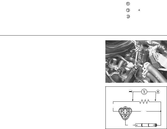
5)Connect 3 new 1.5 V batteries in series, 1 kΩ resistor and the multi-circuit tester as shown in the illustration.
09900-25008: Multi-circuit tester set
Tester knob indication: Voltage ( )
W |
1 kΩ |
|
L/Y |
|
B/L |

4-34 FI SYSTEM DIAGNOSIS
6)Under this condition, if a suitable screwdriver touching the
pick-up surface of the CMP sensor is moved, the tester reading voltage changes (0.8 V and less ↔ 4.3 V and more).
.
Is the voltage OK? |
|
|
|
|
ECM couplers (Harness side) |
||
• B/Y, B/Br or R wire open or shorted to ground |
|||
(Black) |
(Gray) |
||
|
|||
•Loose or poor contacts on the CKP sensor coupler or ECM coupler (terminal C, S or A)
•If wires and connection are OK, intermittent
YES |
trouble or faulty ECM. |
|
|
|
|
|
|
|
|
|
|
|
|
|
|
|
|
|
|||
|
• Recheck each terminal and wire harness for |
|
E |
|||||||
|
open circuit and poor connection. |
|
|
|||||||
|
• Replace the ECM with a known good one, and |
|
||||||||
|
|
|
|
|
|
|
||||
|
inspect it again. |
|
|
|
|
|
|
|
|
|
|
|
|
|
|
|
|
|
|||
|
• Inspect that metal particles or foreign material |
|
|
|
|
|
|
|||
|
stuck on the CMP sensor and rotor tip. |
P |
||||||||
|
|
L |
||||||||
NO |
• If there are no metal particles and foreign mate- |
|
|
|
|
|
|
|||
|
|
|
M |
|
|
|
|
|
|
|
|
rial, then replace the CMP sensor with a new |
|
|
|
|
|
|
|||
|
one. |
|
|
|
|
|
|
|
|
|
|
|
A |
|
|
|
|
|
|
|
|
|
S |
|
|
|
|
|
|
|
|
|
|
|
|
|
|
|
|
|
|
|
|
|
|
|
|
|
|
|
|
|
|
|
When using the multi-circuit tester, do not storongly |
|
|
|
|
|
|
||||
touch the terminal of the ECM coupler with a needle |
|
|
|
|
|
|
||||
pointed tester probe to prevent the terminal damage |
|
|
|
|
|
|
||||
or terminal bend. |
|
|
|
|
|
|
|
|
|
|
|
|
|
|
|
|
|
|
|
|
|
7)After repairing the trouble, clear the DTC using SDS tool. ( 4-27)

FI SYSTEM DIAGNOSIS 4-35
“C12” (P0335) CKP SENSOR CIRCUIT MALFUNCTION
DETECTED CONDITION |
POSSIBLE CAUSE |
The signal does not reach ECM for 3 sec. or more, • Metal particles or foreign material being stuck on after receiving the starter signal. the CKP sensor and rotor tip
• CKP sensor circuit open or short
• CKP sensor malfunction
• ECM malfunction
|
|
ECM |
CKP sensor |
|
|
B |
G/W |
CKP |
G |
O/BI |
CKP |
|
|
|
|
|
E |
|
|
|
|
||
|
|
|
|
|
|
|
|
|
|||
|
|
|
|
L |
|
|
|
|
|||
INSPECTION |
|
P |
1 |
|
|
|
|
|
|||
Step 1 |
M |
|
|
|
|
|
|
|
|
||
1) |
Turn the ignition switch OFF. |
|
|
|
|
|
|
|
|
||
|
|
|
|
|
|
|
|
|
|
||
2) |
Lift and support the fuel tank. ( 5-3) |
|
|
|
|
|
|
|
|
|
|
3) |
A |
|
|
|
|
|
|
|
|
|
|
Check the CKP sensor coupler for loose or poor contacts. |
|
|
|
|
|
|
|
||||
|
If OK, then measure the CKP sensor resistance. |
|
|
|
|
|
|
|
|
||
|
S |
|
|
|
|
|
|
|
|
|
|
4) |
Disconnect the CKP sensor coupler and measure the resis- |
|
|
|
|
|
|
||||
|
1 |
|
|
|
|
|
|||||
|
|
|
|
|
|
||||||
|
tance. |
|
|
|
|
|
|
|
|
|
|
|
|
|
|
|
|
|
|
|
|
|
|
|
|
|
|
|
|
|
|
|
|
|
|
CKP sensor resistance: 142 – 194 Ω (B – G)

4-36 FI SYSTEM DIAGNOSIS
5) If OK, then check the continuity between each terminal and |
1 |
ground. |
|
CKP sensor continuity: ∞ Ω (Infinity)
(B – Ground)
(G – Ground)
09900-25008: Multi-circuit tester set
Tester knob indication: Resistance (Ω)
Are the resistance and continuity OK?
YES |
Go to step 2. |
NO |
Replace the CKP sensor with a new one. |
6)After repairing the trouble, clear the DTC using SDS tool. ( 4-27)
Step 2 |
|
|
|
2 |
|
|
|
|
|
|
1) Crank the engine a few seconds with the starter motor, and |
|
|
|
|
|
V |
|
|||
measure the CKP sensor peak voltage at the coupler. |
|
|
|
|
|
|
||||
|
|
E |
|
|
|
|
|
|||
|
|
|
|
|
|
|
||||
2) Repeat the above test procedure a few times and measure |
|
|
|
|
|
|
|
|||
|
|
|
|
|
|
|
||||
the highest peak voltage. |
|
|
|
|
|
|||||
|
|
P |
|
|||||||
CKP sensor peak voltage: 0.28 V and more |
|
L |
|
|
|
|
|
|||
(+ B – - G) |
|
|
|
|
|
|
|
|
|
|
|
M |
|
|
|
|
|
|
|
|
|
1 Peak volt adaptor |
|
|
|
|
|
|
|
|
||
A |
|
|
|
|
|
|
|
|
|
|
09900-25008: Multi-circuit tester set |
|
|
|
|
|
|
|
|
|
|
Tester knob indication: Voltage ( ) |
|
|
|
|
|
|
|
|
|
|
S |
|
|
|
|
|
|
|
|
|
|

FI SYSTEM DIAGNOSIS 4-37
. |
|
|
|
Is the voltage OK? |
2 |
|
|
|
• G/W or O/BI wire open or shorted to ground. |
ECM couplers (Harness side) |
|
|
(Black) |
(Gray) |
|
|
• Loose or poor contacts on the CKP sensor cou- |
||
|
|
|
|
|
pler or ECM coupler (terminal D or U). |
|
|
|
• If wire and connection are OK, intermittent trou- |
|
|
YES |
ble or faulty ECM. |
|
|
|
• Recheck each terminal and wire harness for |
|
|
|
open circuit and poor connection. |
|
|
|
• Replace the ECM with a known good one, and |
|
|
|
inspect it again. |
|
|
|
• Inspect that metal particles or foreign material |
|
|
|
stuck on the CKP sensor and rotor tip. |
|
|
NO |
• If there are no metal particles and foreign mate- |
|
||||
|
|
rial, then replace the CKP sensor with a new |
|
|||
|
|
one. |
|
|
|
|
|
|
|
|
|
|
|
|
|
|
|
|
|
|
|
|
E |
||||
When using the multi-circuit tester, do not storongly |
|
|
||||
touch the terminal of the ECM coupler with a needle |
|
|
||||
|
|
|
L |
|||
pointed tester probe to prevent the terminal damage |
|
|||||
or terminal bend. |
|
|
|
|
||
|
|
|
P |
|
||
3) After repairing the trouble, clear the DTC using SDS tool. |
|
|||||
( 4-27) |
|
M |
|
|||
|
|
|
A |
|
||
|
|
|
S |
|
||

4-38 FI SYSTEM DIAGNOSIS
“C13” (P0105-H/L) IAP SENSOR CIRCUIT MALFUNCTION
|
|
DETECTED CONDITION |
|
POSSIBLE CAUSE |
|
|
|
|
|
C13 |
IAP sensor voltage is not within the fol- |
• |
Clogged vacuum passage between throttle body |
|
|
|
lowing range. |
|
and IAP sensor. |
|
|
0.5 V Sensor voltage < 4.85 V |
• |
Air being drawn from vacuum passage between |
|
|
NOTE: |
|
throttle body and IAP sensor. |
|
|
• |
IAP sensor circuit open or shorted to ground. |
|
|
|
Note that atmospheric pressure varies |
||
|
|
depending on weather conditions as |
• |
IAP sensor malfunction. |
|
|
well as altitude. |
• |
ECM malfunction. |
|
|
|
|
|
|
|
Take that into consideration when |
|
|
|
|
inspecting voltage. |
|
|
|
|
|
|
|
P0105 |
H |
Sensor voltage is higher than specified |
• |
IAP sensor circuit open or shorted to VCC or |
|
value. |
|
ground circuit open. |
|
|
L |
Sensor voltage is lower than specified |
• |
IAP sensor circuit shorted to ground or VCC cir- |
|
value. |
|
cuit open. |
|
|
|
|
||
|
|
|
|
|
IAP sensor
|
|
|
|
|
|
|
E |
ECM |
|
|
|
|
|
|
|
|
|
||
|
|
|
|
|
|
|
|
||
|
|
|
|
|
|
L |
|
|
|
|
|
|
|
|
|
|
|
||
|
|
|
|
G/B |
P |
|
IAP |
||
|
|
|
|
B/Br |
|
|
|
E2 |
|
|
|
|
|
|
|
|
|
||
|
|
|
|
M |
|
|
VCC |
||
|
|
|
|
R |
|
|
|
||
|
|
|
A |
|
|
|
|
|
|
|
|
|
S |
|
|
|
|
|
|
INSPECTION |
1 |
Step 1 (When indicating C13:) |
|
|
1)Turn the ignition switch OFF.
2)Lift and support the fuel tank. ( 5-3)
3)Check the IAP sensor coupler for loose or poor contacts. If OK, then measure the IAP sensor input voltage.


4-42 FI SYSTEM DIAGNOSIS
Step 3 |
|
3 |
|
||
1) |
Turn the ignition switch OFF. |
|
|
|
|
2) |
Remove the IAP sensor. |
|
|
||
3) |
Connect the vacuum pump gauge to the vacuum port of the |
|
|
||
|
IAP sensor. |
|
v |
||
|
Arrange 3 new 1.5 V batteries in series 1 (check that total |
|
|||
|
voltage is 4.5 – 5.0 V) and connect - terminal to the ground |
|
|
||
|
terminal 2 and + terminal to the VCC terminal 3. |
|
|
||
4)Check the voltage between V-out 4 and ground. Also, check
if voltage reduces when vacuum is applied up to 53 kPa (400 mmHg) by using vacuum pump gauge. ( 4-43)
09917-47011: Vacuum pump gauge
09900-25008: Multi-circuit tester set
Tester knob indication: Voltage ( )
Is the voltage OK? |
|
|
3 |
|
|
|
• G/B, R or B/Br wire open or shorted to ground, |
ECM couplers (Harness side) |
|||
|
E |
(Gray) |
|||
|
or poor 9, A or S connection |
|
(Black) |
||
|
|
L |
|
||
|
• If wire and connection are OK, intermittent trou- |
|
|||
|
|
|
|||
YES |
ble or faulty ECM. |
|
P |
|
|
|
|
|
|||
• Recheck each terminal and wire harness for |
|
|
|||
|
|
|
|||
|
open circuit and poor connection. |
|
|
|
|
|
|
M |
|
|
|
|
• Replace the ECM with a known good one, and |
|
|
||
|
inspect it again. |
A |
|
|
|
NO |
If check result is not satisfactory, replace the IAP |
|
|
||
S |
|
|
|
||
|
|
|
|
||
|
sensor with a new one. |
|
|
|
|
When using the multi-circuit tester, do not storongly touch the terminal of the ECM coupler with a needle pointed tester probe to prevent the terminal damage or terminal bend.
5)After repairing the trouble, clear the DTC using SDS tool. ( 4-27)

FI SYSTEM DIAGNOSIS 4-43
Output voltage (VCC voltage 4.5 – 5.0 V, ambient temp. 20 – 30 °C, 68 – 86 °F)
|
ALTITUDE |
ATMOSPHERIC |
|
OUTPUT |
|
|||||
|
(Reference) |
|
PRESSURE |
|
VOLTAGE |
|
||||
|
|
|
|
|
|
|
|
|
|
|
(ft) |
(m) |
(mmHg) |
kPa |
|
(V) |
|
||||
|
|
|
|
|
|
|
|
|
|
|
0 |
0 |
760 |
100 |
|
|
|
||||
|
|
|
|
|
|
|
|
|
3.1 – 3.6 |
|
|
|
|
|
|
|
|
|
|
|
|
2 000 |
610 |
707 |
94 |
|
|
|
||||
|
|
|
|
|
|
|
|
|
|
|
2 001 |
611 |
707 |
94 |
|
|
|
||||
|
|
|
|
|
|
|
|
|
2.8 – 3.4 |
|
|
|
|
|
|
|
|
|
|
|
|
5 000 |
1 524 |
634 |
85 |
|
|
|
||||
5 001 |
1 525 |
634 |
85 |
|
|
|
||||
|
|
|
|
|
|
|
|
|
2.6 – 3.1 |
|
|
|
|
|
|
|
|
|
|
|
|
8 000 |
2 438 |
567 |
76 |
|
|
|
||||
|
|
|
|
|
|
|
|
|
|
|
8 001 |
2 439 |
567 |
76 |
|
|
|
||||
|
|
|
|
|
|
|
|
|
2.4 – 2.9 |
|
|
|
|
|
|
|
|
|
|
|
|
10 000 |
3 048 |
526 |
70 |
|
|
E |
||||
|
|
|
|
|
|
|
|
|
|
|
|
|
|
|
|
|
|
|
|
|
|
|
|
|
|
|
|
|
|
|
L |
|
|
|
|
|
|
|
|
|
P |
||
|
|
|
|
|
|
M |
||||
|
|
|
|
A |
|
|
|
|||
|
|
|
S |
|
|
|
|
|
||

4-44 FI SYSTEM DIAGNOSIS
“C14” (P0120-H/L) TP SENSOR CIRCUIT MALFUNCTION
|
|
|
|
|
|
DETECTED CONDITION |
|
|
|
POSSIBLE CAUSE |
||||||||||||||
|
|
|
|
|
|
|
|
|
|
|
|
|
|
|
|
|
|
|
|
|
||||
C14 |
|
Output voltage is not within the following |
• |
TP sensor maladjusted |
|
|
|
|||||||||||||||||
|
|
|
|
|
|
range. |
|
|
|
|
|
|
• TP sensor circuit open or short |
|||||||||||
|
|
|
|
|
|
Difference between actual throttle open- |
• |
TP sensor malfunction |
|
|
|
|||||||||||||
|
|
|
|
|
|
ing and opening calculated by ECM is |
• |
ECM malfunction |
|
|
|
|||||||||||||
|
|
|
|
|
|
larger than specified value. |
|
|
|
|
|
|
|
|
|
|
||||||||
|
|
|
|
|
|
0.2 V Sensor voltage < 4.8 V |
|
|
|
|
|
|
|
|
|
|
||||||||
|
|
|
|
|
|
|
|
|
|
|
|
|
|
|
|
|
|
|
|
|||||
P0120 |
H |
|
Sensor voltage is higher than specified |
• TP sensor circuit shorted to VCC or ground circuit |
||||||||||||||||||||
|
|
|
|
value. |
|
|
|
|
|
|
|
open |
|
|
|
|
|
|
|
|
||||
|
|
|
|
|
|
|
|
|
|
|
|
|
|
• TP sensor circuit open or shorted to ground or |
||||||||||
|
|
|
L |
|
Sensor voltage is lower than specified |
|||||||||||||||||||
|
|
|
|
value. |
|
|
|
|
|
|
|
VCC circuit open |
|
|
|
|||||||||
|
|
|
|
|
|
|
|
|
|
|
|
|
|
|
|
|||||||||
|
|
|
|
|
|
|
|
|
|
|
|
|
|
|
|
|
|
|
|
|
|
|
|
|
|
|
|
|
|
|
|
|
|
|
|
|
|
|
|
|
|
|
|
|
|
|
|
ECM |
|
|
|
|
|
|
|
TP sensor |
|
|
|
|
|
|
|
|
|
|
|
|
|
|
|
|
||
|
|
|
|
|
|
|
|
|
|
|
|
|
|
|
|
|
|
|
VCC |
|
||||
|
|
|
|
|
|
|
|
|
|
|
|
|
|
|
|
|
|
|
|
|
|
|
||
|
|
|
|
|
|
|
|
|
|
|
|
|
|
|
|
|
|
|
|
|
|
|
|
|
|
|
|
|
|
|
|
|
|
|
|
|
R |
|
|
|
|
|
|
|
|
|
|
|
|
|
|
|
|
|
|
|
|
|
|
|
|
|
|
|
|
|
|
|
|
|
|
|||
|
|
|
|
|
|
|
|
|
|
|
|
|
|
|
|
|
|
|
E |
|
||||
|
|
|
|
|
|
|
|
|
|
|
|
|
|
|
|
|
|
|
|
|||||
|
|
|
|
|
|
|
|
|
|
|
|
P/B |
|
|
|
|
||||||||
|
|
|
|
|
|
|
|
|
|
|
|
|
|
|
|
|
|
|
|
|
TP |
|
||
|
|
|
|
|
|
|
|
|
|
|
|
|
|
|
L |
|
|
|||||||
|
|
|
|
|
|
|
|
|
|
|
|
|
|
|
|
|
|
|
|
|||||
|
|
|
|
|
|
|
|
|
|
|
|
B/Br |
|
|
|
E2 |
|
|||||||
|
|
|
|
|
|
|
|
|
|
|
|
|
P |
|
|
|
|
|||||||
|
|
|
|
|
|
|
|
|
|
|
|
|
|
|
|
|
|
|
|
|
||||
|
|
|
|
|
|
|
|
|
|
|
|
|
|
|
|
|
|
|
|
|
||||
|
|
|
|
|
|
|
|
|
|
|
|
|
|
|
|
|
|
|
|
|
|
|
||
|
|
|
|
|
|
|
|
|
M |
|
|
|
|
|
|
|
|
|||||||
INSPECTION |
|
|
|
|
|
|
|
|||||||||||||||||
|
1 |
|
|
|
|
|
|
|||||||||||||||||
Step 1 (When indicating C14:) |
|
|
|
|
|
|
|
|
|
|
|
|
|
|
|
|
||||||||
|
|
|
|
|
|
|
|
|
|
|
|
|
|
|
|
|||||||||
1) |
|
|
|
|
|
S |
|
|
|
|
|
|
|
|
|
|
||||||||
Turn the ignition switch to OFF. |
A |
|
|
|
|
|
|
|
|
|
|
|||||||||||||
2) |
Lift and support the fuel tank. ( 5-3) |
|
|
|
|
|
|
|
|
|
|
|||||||||||||
3) |
Check the TP sensor coupler for loose or poor contacts. |
|
|
|
|
|
|
|
|
|||||||||||||||
|
If OK, then measure the TP sensor input voltage. |
|
|
|
|
|
|
|
|
|
|
|||||||||||||
4) |
Disconnect the TP sensor coupler. |
|
|
|
|
|
|
|
|
|
|
|||||||||||||
5) |
Turn the ignition switch ON. |
|
|
|
|
|
|
|
|
|
|
|
|
|
|
|
|
|||||||
6) |
Measure the voltage at the R wire B and ground. |
|
|
|
|
|
|
|
|
|
|
|||||||||||||
7) |
If OK, then measure the voltage at the R wire B and B/Br |
|
|
|
|
|
|
|
|
|||||||||||||||
|
wire C. |
|
|
|
|
|
|
|
|
|
|
|
|
|
|
|
|
|
|
|
|
|||

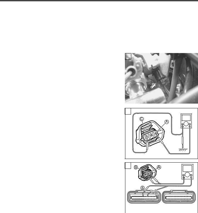
4-46 FI SYSTEM DIAGNOSIS
Is the continuity OK?
YES |
Go to Step 2. |
NO |
P/B wire shorted to VCC, or B/Br wire open |
9)After repairing the trouble, clear the DTC using SDS tool. ( 4-27)
Step 1 (When indicating P0120-L:) |
1 |
|
|
1)Turn the ignition switch OFF.
2)Lift and support the fuel tank. ( 5-3)
3)Check the TP sensor coupler for loose or poor contacts. If OK, then check the TP sensor lead wire continuity.
4) Disconnect the TP sensor coupler. |
|
1 |
|
|
5) Check the continuity between P/B wire A and ground. |
|
|
|
|
6) Also, check the continuity between P/B wire A and B/Br wire |
|
|
||
|
|
L |
|
|
C. If the sound is not heard from the tester, the circuit condi- |
|
E |
|
|
tion is OK. |
P |
|
|
|
|
|
|
|
|
M |
|
|
|
|
A |
|
|
|
|
S |
|
1 |
|
|
7) Disconnect the ECM coupler. |
|
|
! |
|
8) Check the continuity between P/B wire A and terminal 8. |
|
|
|
|
9) Also, check the continuity between R wire B and terminal A. |
|
|
|
|
TPS lead wire continuity: Continuity ( ) |
|
|
|
|
09900-25008: Multi-circuit tester set
09900-25009: Needle pointed probe set
Tester knob indication: Continuity test ( ) |
(Black) |
(Gray) |
|||
|
|
|
|
||
|
|
|
ECM couplers (Harness side) |
||
|
|
|
|
||
|
|
|
|
||
|
|
|
|
|
|
When using the multi-circuit tester, do not storongly |
|
|
|
||
touch the terminal of the ECM coupler with a needle |
|
|
|
||
pointed tester probe to prevent the terminal damage |
|
|
|
||
or terminal bend. |
|
|
|
||
|
|
|
|
|
|
Is the continuity OK? |
|
|
|||
|
|
|
|
|
|
YES |
|
Go to Step 1 ( 4-44) and go to Step 2. |
|
|
|
NO |
|
R wire or P/B wire open, or P/B wire shorted to |
|
|
|
|
ground |
|
|
|
|
|
|
|
|
|
|
|
|
|
|
|
|
10)After repairing the trouble, clear the DTC using SDS tool. |
|
|
|||
( 4-27) |
|
|
|
|
|

FI SYSTEM DIAGNOSIS 4-47
Step 2 |
2 |
|
|
|
1) |
Turn the ignition switch OFF. |
|
|
|
2) |
Disconnect the TP sensor coupler. |
|
|
|
|
|
|
||
|
|
|
||
3) |
Install the test harness to the TP sensor. |
|
|
|
4) |
Check the continuity between terminal A and ground. |
|
|
|
TP sensor continuity: ∞ Ω (Infinity) (Terminal A – Ground)
5) |
If OK, then measure the TP sensor resistance at the test har- |
2 |
|
ness terminals (between terminal A and terminal B). |
|
6) |
Turn the throttle grip and measure the resistance. |
|
TP sensor resistance
Throttle valve is closed: Approx. 1.1 kΩ Throttle valve is opened: Approx. 4.3 kΩ
|
|
E2 |
|
|
|
|
L |
|
|
|
P |
P/B |
|
|
M |
|
|
||
TPS |
R |
ECM |
||
|
B/Br |
|
||
A |
|
|
|
|
|
|
|
|
|
S |
|
|
|
|
7) If OK, then measure the TP sensor resistance at the test har- |
2 |
|
|
ness terminals (between terminal C and terminal D).
TP sensor resistance: Approx. 4.68 kΩ
(Terminal C – Terminal D)
09900-25008: Multi-circuit tester set
09900-28630: TPS test wire harness
Tester knob indication: Resistance (Ω)
Are the continuity and resistance OK? |
2 |
|
|
|
YES |
Go to Step 3. |
|
|
|
NO |
• Reset the TP sensor position correctly. |
|
|
|
• Replace the TP sensor with a new one. |
|
P/B |
|
|
|
|
|
||
8) After repairing the trouble, clear the DTC using SDS tool. |
TPS |
R |
ECM |
|
|
|
|||
( 4-27) |
|
B/Br |
|
|
|
|
|
||
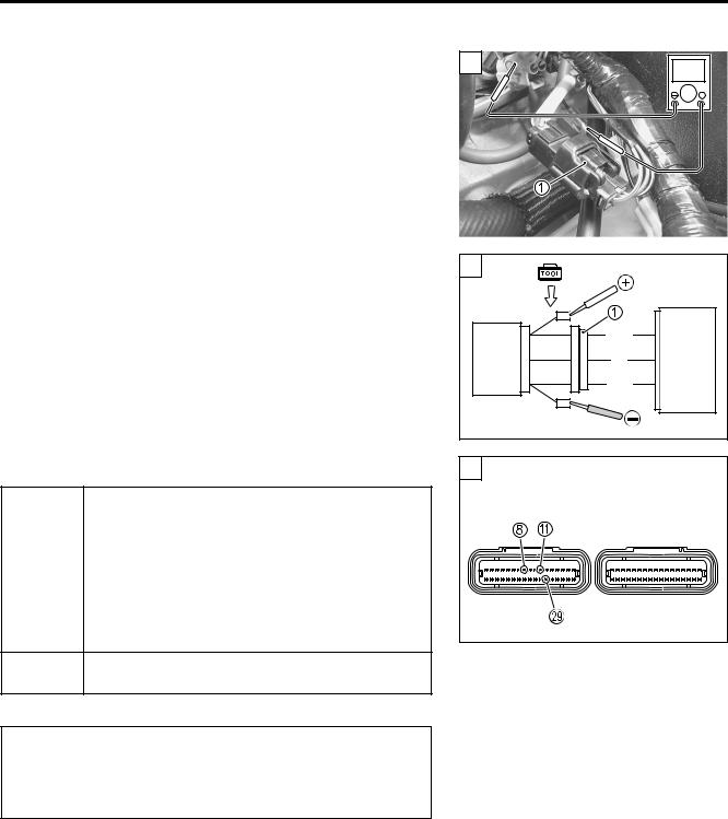
4-48 FI SYSTEM DIAGNOSIS
Step 3 |
3 |
V |
|
1) |
Connect the TP sensor coupler 1 to the test harness. |
|
|
|
|
||
2) |
Turn the ignition switch ON. |
|
|
3) |
Measure the TP sensor output voltage at the coupler |
|
|
|
(between + P/B and - B/Br) by turning the throttle grip. |
|
|
3
Approx. 1.1 V
Approx. 4.3 V
09900-25008: Multi-circuit tester set |
|
P/B |
|
Tester knob indication: Voltage ( ) |
TPS |
R |
ECM |
|
|
B/Br |
|
Is the voltage OK? |
|
|
3 |
E |
|
|
|
• P/B, R or B/Br wire open or shorted to ground, |
|
ECM couplers (Harness side) |
|||
|
L |
(Gray) |
||||
|
or poor 8, A or S connection |
P |
(Black) |
|||
|
|
|
||||
|
|
|
|
|
||
|
• If wire and connection are OK, intermittent trou- |
|
|
|
||
YES |
ble or faulty ECM. |
M |
|
|
|
|
|
|
|
|
|||
|
|
|
|
|
||
|
• Recheck each terminal and wire harness for |
|
|
|
||
|
open circuit and poor connection. |
|
|
|
|
|
|
|
A |
|
|
|
|
|
• Replace the ECM with a known good one, and |
|
|
|
||
|
inspect it again.S |
|
|
|
|
|
NO
If check result is not satisfactory, replace TP sensor with a new one.
When using the multi-circuit tester, do not storongly touch the terminal of the ECM coupler with a needle pointed tester probe to prevent the terminal damage or terminal bend.
4)After repairing the trouble, clear the DTC using SDS tool. ( 4-27)

FI SYSTEM DIAGNOSIS 4-49
“C15” (P0115-H/L) ECT SENSOR CIRCUIT MALFUNCTION
|
|
|
|
DETECTED CONDITION |
|
|
|
POSSIBLE CAUSE |
||||||||||
|
|
|
|
|
|
|
|
|
|
|
|
|
|
|
||||
C15 |
Output voltage is not within the following |
• |
ECT sensor circuit open or short |
|||||||||||||||
|
|
|
|
range. |
|
|
|
|
• |
ECT sensor malfunction |
||||||||
|
|
|
|
0.15 V Sensor voltage < 4.85 V |
• |
ECM malfunction |
||||||||||||
|
|
|
|
|
|
|
|
|
|
|
|
|
|
|
||||
P0115 |
H |
Sensor voltage is higher than specified |
• |
ECT sensor circuit open or ground circuit open |
||||||||||||||
|
|
value. |
|
|
|
|
|
|
|
|
|
|
|
|
||||
|
|
|
|
|
|
|
|
|
• |
ECT sensor circuit shorted to ground |
||||||||
|
|
L |
Sensor voltage is lower than specified |
|||||||||||||||
|
|
value. |
|
|
|
|
|
|
|
|
|
|
|
|
||||
|
|
|
|
|
|
|
|
|
|
|
|
|
|
|
|
|||
|
|
|
|
|
|
|
|
|
|
|
|
|
|
|
|
|||
|
|
|
|
ECT sensor |
|
|
|
|
|
|
|
|
|
|
ECM |
|||
|
|
|
|
|
|
|
|
|
|
|
|
|
|
|
|
|
|
|
|
|
|
|
|
|
|
|
|
|
B/BI |
|
E |
|
ECT |
|
|||
|
|
|
|
|
|
|
|
|
|
|
|
|
||||||
|
|
|
|
|
|
|
|
|
|
|
|
|
||||||
|
|
|
|
|
|
|
|
|
|
B/Br |
|
|
E2 |
|
||||
|
|
|
|
|
|
|
|
|
|
|
|
|
||||||
|
|
|
|
|
|
|
|
|
|
|
|
|
|
|
|
|||
|
|
|
|
|
|
|
|
|
|
|
|
|
|
|
|
|||
|
|
|
|
|
|
|
|
|
|
|
|
|
|
|
|
|||
|
|
|
|
|
|
|
|
|
|
|
|
L |
|
|
||||
|
|
|
|
|
|
|
|
|
|
|
|
|
|
|||||
INSPECTION |
|
|
|
M |
|
|
|
|
|
|
|
|||||||
|
|
|
|
|
1 |
|
|
|
|
|||||||||
|
|
|
P |
|
|
|
|
|
||||||||||
Step 1 (When indicating C15:) |
|
|
|
|
|
|
|
|
|
|||||||||
1) Turn the ignition switch OFF. |
|
|
|
|
|
|
|
|
|
|||||||||
2) Lift and support the fuel tank. ( 5-3) |
|
|
|
|
|
|
|
|
||||||||||
|
|
|
|
|
S |
|
|
|
|
|
|
|
|
|
||||
3) Check the ECT sensor couplerAfor loose or poor contacts. |
|
|
|
|
|
|
||||||||||||
If OK, then measure the ECT sensor voltage at the wire side |
|
|
|
|
|
|
||||||||||||
coupler. |
|
|
|
|
|
|
|
|
|
|
|
|
|
|
|
|||
4) Disconnect the coupler and turn the ignition switch ON. |
|
|
|
|
|
|
||||||||||||
5) Measure the voltage between B/Bl wire terminal A and |
|
|
|
|
|
|
||||||||||||
ground. |
|
|
|
|
|
|
|
|
|
|
|
|
|
|
|
|||
6) If OK, then measure the voltage between B/Bl wire terminal |
|
|
|
|
|
|
||||||||||||
A and B/Br wire terminal B. |
|
|
|
|
|
|
|
|
|
|||||||||
ECT sensor voltage: |
4.5 – 5.5 V |
|
|
|
|
|
|
|
|
|||||||||
|
|
|
1 |
|
|
|
|
|||||||||||
|
|
|
|
|
|
|
(+ B/Bl – - Ground) |
|
|
|
|
|
|
|
|
|||
|
|
|
|
|
|
|
(+ B/Bl – - B/Br) |
|
|
|
|
|
|
|
|
|||
09900-25008: Multi-circuit tester set |
|
|
|
|
|
|
|
V |
||||||||||
|
|
|
|
|
|
|
|
|||||||||||
Tester knob indication: Voltage ( )
Is the voltage OK?
YES |
Go to Step 2. |
|
|
|
|
|
• Loose or poor contacts on the ECM coupler |
|
NO |
(terminal 0 or S). |
|
• Open or short circuit in the B/Bl wire or B/Br |
||
|
||
|
wire |
|
|
|
4-50 FI SYSTEM DIAGNOSIS
Step 1 (When indicating P0115-H:) |
1 |
|
|
1)Turn the ignition switch OFF.
2)Lift and support the fuel tank. ( 5-3)
3)Check the ECT sensor coupler for loose or poor contacts. If OK, then check the ECT sensor lead wire continuity.
4) Disconnect the ECT sensor coupler and ECM coupler. |
1 |
! |
||||
5) Check the continuity between B/Bl wire A and terminal 0. |
|
|||||
|
|
|||||
6) Also, check the continuity between B/Br wire B and terminal |
|
|
||||
S. |
|
|
|
|
|
|
ECTS lead wire continuity: Continuity ( ) |
|
|
||||
09900-25008: Multi-circuit tester set |
|
|
|
|||
09900-25009: Needle pointed probe set |
(Black) |
(Gray) |
||||
Tester knob indication: Continuity test ( ) |
||||||
CM couplers (Harness side) |
||||||
|
|
|
|
E |
|
|
When using the multi-circuit tester, do not storongly |
|
|||||
L |
|
|||||
touch the terminal of the ECM coupler with a needle |
|
|||||
|
|
|||||
pointed tester probe to prevent the terminal damage |
|
|
||||
or terminal bend. |
|
P |
|
|||
|
M |
|
|
|||
Is the continuity OK? |
|
|
|
|||
A |
|
|
||||
YES |
Go to Step 2. |
|
|
|||
|
|
|
|
|||
NO |
B/Bl or B/Br wire open |
|
|
|
||
|
|
S |
|
|
|
|
7)After repairing the trouble, clear the DTC using SDS tool. ( 4-27)

FI SYSTEM DIAGNOSIS 4-51
Step 1 (When indicating P0115-L:) |
1 |
|
|
1)Turn the ignition switch OFF.
2)Lift and support the fuel tank. ( 5-3)
3)Check the ECT sensor coupler for loose or poor contacts. If OK, then measure the output voltage.
4) |
Disconnect the ECT sensor coupler. |
1 |
|
|
|
|
|
|
|
5) |
Check the continuity between B/Bl wire A and ground. |
|
|
|
|
|
|
|
|
|
If the sound is not heard from the tester, the circuit condition |
|
|
|
|
|
|
|
|
|
|
|
|
|
|
|
|
|
|
|
is OK. |
|
|
|
|
|
|
|
|
|
|
|
|
|
|
|
|
|
|
Tester knob indication: Continuity test ( )
|
|
|
|
|
|
|
|
|
|
||
|
|
L |
|
|
|
|
|
|
|||
6) Connect the ECT sensor coupler and turn the ignition switch |
E1 |
|
|
|
|
|
|||||
ON. |
|
|
|
|
|
|
|
|
|
|
|
7) Measure the voltage between B/Bl wire A and ground. |
|
|
|
|
|
|
|
V |
|
||
|
|
|
|
|
|
|
|
|
|
||
|
M |
|
|
|
|
|
|
|
|
|
|
ECT sensor output voltage: 0.15 – 4.85 VP |
|
|
|
|
|
|
|
|
|||
|
(+ B/BI – - Ground) |
|
|
|
|
|
|
|
|
||
|
A |
|
|
|
|
|
|
|
|
|
|
09900-25008: Multi-circuit tester set |
|
|
|
|
|
|
|
|
|
|
|
|
S |
|
|
|
|
|
|
|
|
|
|
09900-25009: Needle pointed probe set |
|
|
|
|
|
|
|
|
|
|
|
Tester knob indication: Voltage ( ) |
|
|
|
|
|
|
|
|
|
|
|
Are the continuity and voltage OK? |
|
|
|
|
|
|
|
|
|
|
|
|
|
|
|
|
|
|
|
|
|
|
|
YES |
Go to Step 2. |
|
|
|
|
|
|
|
|
|
|
|
|
|
|
|
|
|
|
|
|
|
|
NO |
• B/BI wire shorted to ground |
|
|
|
|
|
|
|
|
|
|
• If wire is OK, go to Step 2. |
|
|
|
|
|
|
|
|
|
|
|
|
|
|
|
|
|
|
|
|
|
|
|
|
|
|
|
|
|
|
|
|
|
|
|
8)After repairing the trouble, clear the DTC using SDS tool. ( 4-27)

4-52 FI SYSTEM DIAGNOSIS
Step 2 |
2 |
|
1) |
Turn the ignition switch OFF. |
|
2) |
Disconnect the ECT sensor coupler. |
|
3) |
Measure the ECT sensor resistance. |
|
ECT sensor resistance:
Approx. 2.45 kΩ at 20 °C (68 °F)
(Terminal – Terminal)
09900-25008: Multi-circuit tester set
Tester knob indication: Resistance (Ω)
Refer to page 7-7 for details.
Is the resistance OK? |
|
|
|
|
|
|
• B/Bl or B/Br wire open or shorted to ground, or |
2 |
|
||
|
poor 0 or S connection. |
|
ECM couplers (Harness side) |
||
|
• If wire and connection are OK, intermittent trou- |
(Black) |
(Gray) |
||
|
|
|
|||
YES |
ble or faulty ECM. |
|
E |
|
|
• Recheck each terminal and wire harness for |
|
||||
|
|
||||
|
open circuit and poor connection. |
|
|
||
|
|
L |
|
||
|
• Replace the ECM with a known good one, and |
|
|||
|
inspect it again. |
P |
|
||
Replace the ECT sensor with a new one. |
|
||||
NO |
|
|
|
||
|
|
M |
|
|
|
|
|
A |
|
|
|
When using the multi-circuit tester, do not storongly |
|
|
|||
touch the terminal of the ECM coupler with a needle |
|
|
|||
|
|
S |
|
|
|
pointed tester probe to prevent the terminal damage |
|
|
|||
or terminal bend. |
|
|
|
|
|
4)After repairing the trouble, clear the DTC using SDS tool. ( 4-27)
ECT sensor specification
Engine Coolant Temp |
Resistance |
|
|
|
|
20 |
°C (68 °F) |
Approx. 2.45 kΩ |
50 °C (122 °F) |
Approx. 0.811 kΩ |
|
80 °C (176 °F) |
Approx. 0.318 kΩ |
|
110 |
°C (230 °F) |
Approx. 0.142 kΩ |

FI SYSTEM DIAGNOSIS 4-53
“C21” (P0110-H/L) IAT SENSOR CIRCUIT MALFUNCTION
|
|
|
|
DETECTED CONDITION |
|
|
|
|
|
POSSIBLE CAUSE |
||||||||
|
|
|
|
|
|
|
|
|
|
|
|
|
|
|
|
|
||
C21 |
Output voltage is not within the following |
• |
IAT sensor circuit open or short |
|||||||||||||||
|
|
|
|
range. |
|
• |
IAT sensor malfunction |
|||||||||||
|
|
|
|
0.15 V Sensor voltage < 4.85 V |
• |
ECM malfunction |
||||||||||||
|
|
|
|
|
|
|
|
|
|
|
|
|
|
|
|
|
||
P0110 |
H |
Sensor voltage is higher than specified |
• |
IAT sensor circuit open or ground circuit open |
||||||||||||||
|
|
value. |
|
|
|
|
|
|
|
|
|
|
|
|||||
|
|
|
|
|
|
|
|
|
• |
IAT sensor circuit shorted to ground |
||||||||
|
|
L |
Sensor voltage is lower than specified |
|||||||||||||||
|
|
value. |
|
|
|
|
|
|
|
|
|
|
|
|||||
|
|
|
|
|
|
|
|
|
|
|
|
|
|
|
||||
|
|
|
|
|
|
|
|
|
|
|
|
|
|
|
|
|
|
|
|
|
|
|
IAT sensor |
|
|
|
|
|
|
|
|
|
ECM |
||||
|
|
|
|
|
|
|
|
|
|
|
|
|
|
|
||||
|
|
|
|
|
|
|
|
|
|
|
Dg |
|
|
|
|
IAT |
|
|
|
|
|
|
|
|
|
|
|
|
|
|
|
|
|
|
|||
|
|
|
|
|
|
|
|
|
|
|
|
|
|
|
|
|
|
|
|
|
|
|
|
|
|
|
|
|
B/Br |
|
|
|
|
|
E2 |
|
|
|
|
|
|
|
|
|
|
|
|
|
E |
|
|
|||||
|
|
|
|
|
|
|
|
|
|
|
|
|
|
|
|
|||
|
|
|
|
|
|
|
|
|
|
|
|
|
|
|
|
|||
|
|
|
|
|
|
|
|
|
|
|
|
|
|
|
|
|||
|
|
|
|
|
|
|
|
|
|
|
|
|
|
|
|
|||
|
|
|
|
|
|
|
|
|
|
|
|
|
|
|
||||
|
|
|
|
|
|
|
|
|
|
|
L |
|||||||
INSPECTION |
P |
|
|
|
|
|
|
|||||||||||
|
1 |
|
|
|
|
|||||||||||||
M |
|
|
|
|
|
|
|
|||||||||||
Step 1 (When indicating C21:) |
|
|
|
|
|
|
|
|
||||||||||
|
|
|
|
|
|
|
|
|
|
|
||||||||
1) Turn the ignition switch OFF. |
|
|
|
|
|
|
|
|
|
|
|
|||||||
|
|
|
|
|
|
|
A |
|
|
|
|
|
|
|
|
|
|
|
2) Lift and support the fuel tank. ( 5-3) |
|
|
|
|
|
|
|
|
|
|
||||||||
3) Check the IAT sensor coupler for loose or poor contacts. |
|
|
|
|
|
|
||||||||||||
If OK, then measure the IAT sensor voltage at the wire side |
|
|
|
|
|
|
||||||||||||
coupler. |
|
S |
|
|
|
|
|
|
|
|
|
|
||||||
4) Disconnect the coupler and turn the ignition switch ON. |
|
|
|
|
|
|
||||||||||||
5) Measure the voltage between Dg wire terminal |
A and |
|
|
|
|
|
|
|||||||||||
|
1 |
|
|
|
|
|||||||||||||
ground. |
|
|
|
|
|
|
|
|
|
|
|
|
|
|
|
|||
6) If OK, then measure the voltage between Dg wire terminal A |
|
|
|
|
|
|
||||||||||||
and B/Br wire terminal B. |
|
|
|
|
|
|
|
|
|
|
V |
|||||||
IAT sensor input voltage: 4.5 – 5.5 V |
|
|
|
|
|
|
|
|
|
|
||||||||
|
|
|
|
|
|
|
|
(+ Dg – - Ground) |
|
|
|
|
|
|
|
|
||
|
|
|
|
|
|
|
|
(+ Dg – - B/Br) |
|
|
|
|
|
|
|
|
|
|
09900-25008: Multi-circuit tester set
Tester knob indication: Voltage ( )
Is the voltage OK?
YES |
Go to Step 2. |
|
|
|
|
|
• |
Loose or poor contacts on the ECM coupler |
NO |
|
(terminal Q or S) |
|
• |
Open or short circuit in the Dg wire or B/Br wire |

4-54 FI SYSTEM DIAGNOSIS
Step 1 (When indicating P0110-H:) |
1 |
1)Turn the ignition switch OFF.
2)Lift and support the fuel tank. ( 5-3)
3)Check the IAT sensor coupler for loose or poor contacts. If OK, then check the IAT sensor lead wire continuity.
4) Disconnect the IAT sensor coupler and ECM coupler. |
1 |
! |
||||
5) Check the continuity between Dg wire A and terminal Q. |
|
|||||
|
|
|||||
6) Also, check the continuity between B/Br wire B and terminal |
|
|
||||
S. |
|
|
|
|
|
|
IATS lead wire continuity: Continuity ( ) |
|
|
||||
09900-25008: Multi-circuit tester set |
|
|
|
|||
09900-25009: Needle pointed probe set |
(Black) |
(Gray) |
||||
Tester knob indication: Continuity test ( ) |
||||||
CM couplers (Harness side) |
||||||
|
|
|
|
E |
|
|
|
|
|
|
|
||
When using the multi-circuit tester, do not storongly |
L |
|
||||
touch the terminal of the ECM coupler with a needle |
|
|||||
|
|
|||||
pointed tester probe to prevent the terminal damage |
|
|
||||
or terminal bend. |
|
P |
|
|||
|
M |
|
|
|||
Is the continuity OK? |
|
|
|
|||
A |
|
|
||||
YES |
Go to Step 2. |
|
|
|||
|
|
|
|
|||
NO |
Dg wire or B/Br wire open |
|
|
|
||
|
|
S |
|
|
|
|
7)After repairing the trouble, clear the DTC using SDS tool. ( 4-27)


4-56 FI SYSTEM DIAGNOSIS
Step 2 |
2 |
|
1)Turn the ignition switch OFF.
2)Measure the IAT sensor resistance.
IAT sensor resistance: Approx. 2.45 kΩ at 20 °C (68 °F)
(Terminal – Terminal)
09900-25008: Multi-circuit tester set
Tester knob indication: Resistance (Ω)
Is the resistance OK? |
2 |
|
|
|
• Dg or B/Br wire open or shorted to ground, or |
|
ECM couplers (Harness side) |
||||||||
|
|
|
(Black) |
|
(Gray) |
|||||||
|
|
poor Q or S connection |
|
|
|
|||||||
|
|
|
|
|
|
|
|
|
||||
|
|
• If wire and connection are OK, intermittent trou- |
|
|
|
|
|
|
||||
YES |
ble or faulty ECM. |
|
|
|
|
|
|
|
|
|||
• Recheck each terminal and wire harness for |
|
|
|
|
|
|
||||||
|
|
|
|
|
|
|||||||
|
|
|
|
|
|
|
|
|||||
|
|
open circuit and poor connection. |
|
|
|
|
|
|
||||
|
|
• Replace the ECM with a known good one, and |
|
|
|
|
|
|
||||
|
|
inspect it again. |
|
|
|
|
|
|
|
|
||
|
|
|
|
|
E |
|
|
|||||
|
|
|
|
|
|
|
||||||
NO |
|
Replace the IAT sensor with a new one. |
|
|
|
|||||||
|
|
|
|
|
|
|
|
|||||
|
|
|
|
L |
|
|
||||||
|
|
|
|
|
|
|
|
|
||||
When using the multi-circuit tester, do not storongly |
|
|
||||||||||
|
|
|
|
|
|
P |
|
|
||||
touch the terminal of the ECM coupler with a needle |
|
|
|
|
|
|
||||||
pointed tester probe to prevent the terminal damage |
|
|
|
|
|
|
||||||
or terminal bend. |
|
|
|
M |
|
|
|
|
|
|
||
|
|
A |
|
|
|
|
|
|
||||
|
|
|
|
|
|
|
|
|
|
|
||
IAT sensor specification |
|
|
|
|
|
|
||||||
|
|
|
S |
|
|
|
|
|
|
|
||
Intake Air Temp |
|
|
|
Resistance |
|
|
|
|
|
|
||
|
|
|
|
|
|
|
|
|
|
|
||
|
20 °C (68 °F) |
|
|
Approx. 2.45 kΩ |
|
|
|
|
|
|
||
|
50 °C (122 °F) |
|
|
Approx. 0.808 kΩ |
|
|
|
|
|
|
||
|
80 °C (176 °F) |
|
|
Approx. 0.322 kΩ |
|
|
|
|
|
|
||
|
110 °C (230 °F) |
|
|
Approx. 0.148 kΩ |
|
|
|
|
|
|
||
NOTE:
IAT sensor resistance measurement method is the same way as that of the ECT sensor. Refer to page 7-7 for details.

 AP
AP E2
E2  VCC
VCC


Step 3 |
3 |
|
|
1) |
Remove the AP sensor. |
|
|
|
|
||
2) |
Connect the vacuum pump gauge to the vacuum port of the |
|
|
|
AP sensor. |
|
|
|
Arrange 3 new 1.5 V batteries in series 1 (check that total |
|
|
|
voltage is 4.5 – 5.0 V) and connect - terminal to the ground |
|
|
|
terminal 2 and + terminal to the VCC terminal 3. |
|
|
3) |
Check the voltage between V-out 4 and ground. Also, check |
|
|
|
if voltage reduces when vacuum is applied up to 53 kPa (400 |
|
|
|
mmHg) by using vacuum pump gauge. ( Below) |
|
|
|
|
|
|
09917-47011: Vacuum pump gauge
09900-25008: Multi-circuit tester set
Tester knob indication: Voltage ( )
Is the voltage OK? |
|
|
|
3 |
|
|
• G/Y, R or B/Br wire open or shorted to ground, |
ECM couplers (Harness side) |
|||||
(Black) |
(Gray) |
|||||
or poor P, A or S connection. |
|
|||||
|
E |
|
||||
• If wire and connection are OK, intermittent trou- |
|
|||||
ble or faulty ECM. |
|
|
|
|||
YES |
|
|
|
|
||
• Recheck each terminal and wire harness for |
|
|||||
open circuit and poor connection. |
L |
|
||||
|
|
|
|
|||
• Replace the ECM with a known good one, and |
|
|
||||
inspect it again. |
|
P |
|
|
||
|
|
|
|
|||
If check result is not satisfactory, replace AP sen- |
|
|
||||
NO |
|
M |
|
|
||
sor with a new one. |
|
|
||||
|
A |
|
|
|
||
When using the multi-circuit tester, do not storongly |
|
|
||||
|
S |
|
|
|
|
|
touch the terminal of the ECM coupler with a needle |
|
|
||||
pointed tester probe to prevent the terminal damage |
|
|
||||
or terminal bend. |
|
|
|
|
|
|
4)After repairing the trouble, clear the DTC using SDS tool. ( 4-27)

4-62 FI SYSTEM DIAGNOSIS
Output voltage (VCC voltage 4.5 – 5.0 V, ambient temp. 20 – 30 °C, 68 – 86 °F)
|
ALTITUDE |
ATMOSPHERIC |
OUTPUT |
|
||||||
|
(Reference) |
|
PRESSURE |
VOLTAGE |
|
|||||
|
|
|
|
|
|
|
|
|
|
|
(ft) |
(m) |
(mmHg) |
|
kPa |
(V) |
|
||||
|
|
|
|
|
|
|
|
|
|
|
0 |
0 |
760 |
|
100 |
|
|
||||
|
|
|
|
|
|
|
|
|
3.1 – 3.6 |
|
|
|
|
|
|
|
|
|
|
|
|
2 000 |
610 |
707 |
|
94 |
|
|
||||
|
|
|
|
|
|
|
|
|
|
|
2 001 |
611 |
707 |
|
94 |
|
|
||||
|
|
|
|
|
|
|
|
|
2.8 – 3.4 |
|
|
|
|
|
|
|
|
|
|
|
|
5 000 |
1 524 |
634 |
|
85 |
|
|
||||
5 001 |
1 524 |
634 |
|
85 |
|
|
||||
|
|
|
|
|
|
|
|
|
2.6 – 3.1 |
|
|
|
|
|
|
|
|
|
|
|
|
8 000 |
2 438 |
567 |
|
76 |
|
|
||||
|
|
|
|
|
|
|
|
|
|
|
8 001 |
2 439 |
567 |
|
76 |
|
|
||||
|
|
|
|
|
|
|
|
|
2.4 – 2.9 |
|
|
|
|
|
|
|
|
|
|
|
|
10 000 |
3 048 |
526 |
|
70 |
|
E |
||||
|
|
|
|
|
|
|
|
|
|
|
|
|
|
|
|
|
|
|
|
|
|
|
|
|
|
|
|
|
|
|
|
L |
|
|
|
|
|
|
|
|
|
P |
|
|
|
|
|
|
|
|
|
M |
||
|
|
|
|
|
|
A |
|
|
||
|
|
|
|
S |
|
|
||||

FI SYSTEM DIAGNOSIS 4-63
“C23” (P1651-H/L) TO SENSOR CIRCUIT MALFUNCTION
|
|
DETECTED CONDITION |
|
|
POSSIBLE CAUSE |
||||||||
|
|
|
|
|
|
|
|
|
|
|
|
|
|
C23 |
The sensor voltage should be the follow- |
• |
TO sensor circuit open or short |
||||||||||
|
|
ing for 2 sec. and more, after ignition |
• |
TO sensor malfunction |
|
|
|||||||
|
|
switch is turned ON. |
|
|
• |
ECM malfunction |
|
|
|||||
|
|
0.2 V Sensor voltage < 4.8 V |
|
|
|
|
|
|
|
||||
|
|
|
|
|
|
|
|
|
|
|
|
|
|
P1651 |
H |
Sensor voltage is higher than specified |
• |
TO sensor circuit shorted to VCC or ground circuit |
|||||||||
|
value. |
|
|
|
open |
|
|
||||||
|
|
|
|
|
|
• |
TO sensor circuit open or shorted to ground or |
||||||
|
L |
Sensor voltage is lower than specified |
|||||||||||
|
value. |
|
|
|
VCC circuit open |
|
|
||||||
|
|
|
|
|
|
|
|||||||
|
|
|
|
|
|
|
|
|
|
|
|
|
|
|
|
TO sensor |
|
|
|
|
|
|
|
ECM |
|||
|
|
|
|
|
|
|
|
|
|
|
|||
|
|
|
|
|
|
R |
|
E |
|
VCC |
|
||
|
|
|
|
|
|
|
|
|
|||||
|
|
|
|
|
|
B |
|
|
TOS |
|
|||
|
|
|
|
|
|
|
|
|
|
|
|||
|
|
|
|
|
|
|
|
|
|
|
|||
|
|
|
|
|
|
|
|
L |
|
|
|||
|
|
|
|
|
|
B/Br |
|
E2 |
|
||||
|
|
|
|
|
|
|
|
|
|
|
|||
|
|
|
|
|
P |
|
|
|
|||||
|
|
|
|
|
|
|
|||||||
|
|
|
|
|
|
|
|
||||||
|
|
|
|
|
|
|
|
||||||
INSPECTION |
M |
|
|
|
|
|
|
||||||
|
1 |
|
|
|
|
||||||||
Step 1 (When indicating C23:) |
|
|
|
|
|
|
|
|
|||||
|
|
|
|
|
|
|
|
|
|||||
|
|
|
|
|
|
|
|
|
|||||
1) Turn the ignition switch OFF. |
|
|
|
|
|
|
|
|
|
||||
|
|
S |
|
|
|
|
|
|
|
|
|
||
2) Remove the frame cover. ( A8-8) |
|
|
|
|
|
|
|
||||||
3) Check the TO sensor coupler for loose or poor contacts. If OK, then measure the TO sensor resistance.
4) Disconnect the TO sensor coupler.
5) Measure the resistance between terminal A and terminal C. |
1 |
|
|
TO sensor resistance: 16.5 – 22.3 kΩ
(Terminal A – Terminal C)
09900-25008: Multi-circuit tester set
Tester knob indication: Resistance (Ω)
Is the resistance OK?
YES |
Go to Step 2. |
|
|
NO |
Replace the TO sensor with a new one. |
|
|


|
|
FI SYSTEM DIAGNOSIS 4-67 |
“C28” (P1655) STV ACTUATOR CIRCUIT MALFUNCTION |
||
|
|
|
DETECTED CONDITION |
|
POSSIBLE CAUSE |
|
|
|
The operation voltage does not reach the STVA. |
• |
STVA malfunction |
ECM does not receive communication signal from |
• STVA circuit open or short |
|
the STVA. |
• |
STVA motor malfunction |
STVA |
ECM |
|
|
B/Lg |
STVA. 1B |
P/W |
STVA. 1A |
G |
STVA. 2B |
W/B |
STVA. 2A |
INSPECTION |
L |
|
||||
|
|
|
|
1 |
|
|
Step 1 |
|
P |
E |
|||
1) Lift and support the fuel tank. ( 5-3) |
|
|
|
|||
|
|
|
|
|
||
2) Remove the air cleaner box. ( 5-14) |
|
|
|
|
|
|
|
M |
|
|
|
||
3) Check the STVA lead wire coupler for loose or poor contacts. |
|
|
|
|||
|
A |
|
|
|
|
|
|
S |
|
|
|
|
|
|
|
|
|
1 |
|
|
4) Turn the ignition switch ON to check the STV operation. |
|
|
||||
(STV operating order: Full open → 95% open) |
|
|
|
|
|
|
|
|
|
|
|
||
Is the operating OK? |
|
|
|
|
|
|
|
|
|
|
|
|
|
YES |
Go to Step 2. |
|
|
|
|
|
|
|
|
|
|
|
|
|
• Loose or poor contacts on the STVA coupler |
|
|
|
||
NO |
• Open or short circuit in the B/Lg, P/W, W/B or G |
|
|
|
||
wires |
|
|
|
|
|
|
|
|
|
|
|
|
|
•If wire and connection are OK, go to Step 2.
5)After repairing the trouble, clear the DTC using SDS tool. ( 4-27)

4-68 FI SYSTEM DIAGNOSIS |
|
|
Step 2 |
2 |
|
1) |
Turn the ignition switch OFF. |
|
2) |
Disconnect the STVA lead wire coupler. |
|
3) |
Check the continuity between each terminal and ground. |
|
STVA continuity: ∞ Ω (Infinity) |
|
|
|
(Terminal – Ground) |
|
4) |
If OK, then measure the STVA resistance (between terminal |
2 |
|
A and terminal B) and (between terminal C and terminal |
|
|
D). |
|
STVA resistance: Approx. 7.0 Ω
(Terminal A – Terminal B)
(Terminal C – Terminal D)
09900-25008: Multi-circuit tester set
Tester knob indication: Resistance (Ω) |
|
E |
|
||
Is the resistance OK? |
|
2 |
|
||
|
• W/B, P/W, G and B/Lg wire open or shorted to |
|
ECM couplers (Harness side) |
||
|
L |
(Gray) |
|||
|
ground, or poor 1, 2, H and I connection |
|
(Black) |
||
|
|
P |
|
|
|
|
• If wire and connection are OK, intermittent trou- |
|
|
|
|
YES |
ble or faulty ECM. |
M |
|
|
|
|
|
|
|
||
|
|
|
|
|
|
|
• Recheck each terminal and wire harness for |
|
|
|
|
|
open circuit and poor connection. |
|
|
|
|
|
|
A |
|
|
|
|
• Replace the ECM with a known good one, and |
|
|
|
|
|
inspect it again.S |
|
|
|
|
NO |
• Loose or poor contacts on the ECM coupler. |
|
|
|
|
• Replace the STVA with a new one. |
|
|
|
||
|
|
|
|
||
|
|
|
|
|
|
When using the multi-circuit tester, do not storongly touch the terminal of the ECM coupler with a needle pointed tester probe to prevent the terminal damage or terminal bend.
5)After repairing the trouble, clear the DTC using SDS tool. ( 4-27)
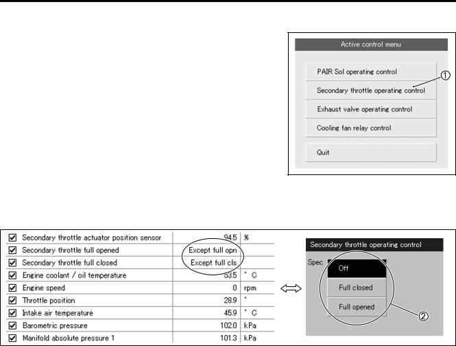
FI SYSTEM DIAGNOSIS 4-69
ACTIVE CONTROL INSPECTION
1)Set up the SDS tool. (Refer to the SDS operation manual for further details.)
2) Turn the ignition switch ON.
3) Click “Secondary throttle operating control” 1.
4) Click each button 2.
At this time, if an operation sound is heard from the STVA, the function is normal.
E
L
P
M
A
S
4-70 FI SYSTEM DIAGNOSIS
“C29” (P1654-H/L) STP SENSOR CIRCUIT MALFUNCTION
|
|
DETECTED CONDITION |
|
POSSIBLE CAUSE |
|
|
|
|
|
C29 |
Signal voltage is not within the following |
• |
STP sensor maladjusted |
|
|
|
range. |
• STP sensor circuit open or short |
|
|
|
Difference between actual throttle open- |
• |
STP sensor malfunction |
|
|
ing and opening calculated by ECM is |
• |
ECM malfunction |
|
|
larger than specified value. |
|
|
|
|
0.15 V Sensor voltage < 4.85 V |
|
|
|
|
|
||
P1654 |
H |
Sensor voltage is higher than specified |
• STP sensor circuit shorted to VCC or ground cir- |
|
|
value. |
|
cuit open |
|
|
|
|
• STP sensor circuit open or shorted to ground or |
|
|
L |
Sensor voltage is lower than specified |
||
|
value. |
|
VCC circuit open |
|
|
|
|
||
|
|
|
|
|
|
|
|
|
|
|
|
|
|
|
|
|
|
|
|
|
|
|
|
|
|
|
|
|
|
|
|
|
|
|
|
|
|
|
|
|
|
|
|
|
|
|
|
|
|
|
|
|
|
|
|
|
|
|
|
|
|
|
|
|
|
|
|
|
|
|
|
|
|
|
|
|
|
|
|
E |
|
|
||||
|
|
|
|
|
|
|
|
|
|
|
|
|
|
|
|
|
|
|
|
|
|
|
|
|||||
|
|
|
|
|
|
|
|
|
|
|
|
|
|
|
|
|
|
|
|
|
|
|
|
|||||
|
|
|
|
|
|
|
|
|
|
|
|
|
|
|
|
|
|
|
|
|
|
|
|
|||||
|
|
|
|
|
|
|
|
|
|
|
|
|
|
|
|
|
|
|
|
|
|
|
|
|||||
|
|
|
|
|
|
|
|
BI |
|
|
|
|
|
|
R |
|
|
|
|
|
|
VCC |
|
|||||
|
|
|
|
|
|
|
|
Y |
|
|
|
|
|
|
|
|
|
|
|
|
|
|
|
STP |
|
|||
|
|
|
|
|
|
|
|
|
|
|
|
Y/W |
|
|
|
|
|
|
|
|||||||||
|
|
|
|
|
|
|
L |
|
||||||||||||||||||||
|
|
|
|
|
|
|
|
|
|
|
|
|
|
|
|
|
|
|
|
|
|
|
|
|
||||
|
|
|
|
|
|
|
|
B |
|
|
|
|
|
|
|
|
B/Br |
|
|
|
|
2 |
|
|||||
|
|
|
|
|
|
|
|
|
|
|
|
|
|
|
|
|
P |
|
|
|
|
|
||||||
|
|
|
|
|
|
|
|
|
|
|
|
|
|
|
|
|
|
|
|
|
|
|||||||
|
|
|
|
|
|
|
|
|
|
|
|
|
|
|
|
|
|
|
|
|
|
|||||||
|
|
|
|
|
|
|
|
|
|
|
|
|
|
|
|
|
|
|
|
|
|
|||||||
|
STP sensor |
|
M |
|
|
|
|
|
|
|
|
|
||||||||||||||||
|
|
|
|
|
|
|
|
|
|
|
||||||||||||||||||
|
|
|
|
|
|
|
|
|
|
|
|
|
|
|
|
|
|
|
|
|
|
|
|
|||||
|
|
|
|
|
|
|
|
|
|
|
|
|
|
|
|
|
|
|
|
|
|
|
|
|||||
|
|
|
|
|
|
|
|
|
|
|
|
|
|
|
|
|
|
|
|
|
|
|
|
|||||
INSPECTION |
A |
|
1 |
|
|
|
|
|
|
|
||||||||||||||||||
|
|
|
|
|
|
|
|
|
|
|
|
|
|
|||||||||||||||
Step 1 (When indicating C29:) |
|
|
|
|
|
|
|
|
|
|
|
|
|
|
|
|||||||||||||
1) |
Turn the ignition switch OFF. |
|
|
|
|
|
|
|
|
|
|
|
|
|
|
|
||||||||||||
2) |
Lift and support the fuel tank.S( 5-3) |
|
|
|
|
|
|
|
|
|
|
|
|
|
|
|||||||||||||
3) |
Check the STP sensor coupler for loose or poor contacts. |
|
|
|
|
|
|
|
|
|
||||||||||||||||||
|
If OK, then measure the STP sensor input voltage. |
|
|
|
|
|
|
|
|
|
||||||||||||||||||
4) |
Disconnect the STP sensor coupler. |
|
|
|
|
|
|
|
|
|
|
|
|
|
|
|||||||||||||
5) |
Turn the ignition switch ON. |
|
|
|
|
|
|
|
|
|
|
|
|
|
|
|
||||||||||||
6) |
Measure the voltage at the R wire A and ground. |
|
|
|
|
|
|
|
|
|
||||||||||||||||||
7) |
Also, measure the voltage at the R wire A and B/Br wire C. |
|
|
|
|
|
|
|
|
|
||||||||||||||||||
STP sensor input voltage: 4.5 – 5.5 V |
1 |
|
|
(+ R – - Ground) |
V |
|
(+ R – - B/Br) |
|
|
|
|
09900-25008: Multi-circuit tester set |
|
|
Tester knob indication: Voltage ( ) |
|
|
Is the voltage OK? |
|
|
YES |
Go to Step 2. |
|
|
• Loose or poor contacts on the ECM coupler |
|
NO |
(terminal A or S) |
|
|
• Open or short circuit in the R wire or B/Br wire |
|


4-72 FI SYSTEM DIAGNOSIS
Step 1 (When indicating P1654-L:) |
1 |
1)Turn the ignition switch OFF.
2)Lift and support the fuel tank. ( 5-3)
3)Check the STP sensor coupler for loose or poor contacts. If OK, then check the STP sensor lead wire continuity.
4) |
Disconnect the STP sensor coupler. |
1 |
|
|
|
|
|
|
|
5) |
Check the continuity between Y/W wire B and ground. |
|
|
|
|
|
|
|
|
|
|
|
|
|
|
|
|
||
|
|
|
|
|
|
|
|
||
6) |
Also, check the continuity between Y/W wire B and B/Br wire |
|
|
|
|
|
|
|
|
|
|
|
|
|
|
|
|
||
|
|
|
|
|
|
|
|
||
|
C. If the sound is not heard from the tester, the circuit condi- |
|
|
|
|
|
|
|
|
|
|
|
|
|
|
|
|
|
|
|
tion is OK. |
|
|
|
|
|
|
|
|
|
|
|
|
|
|
|
|
|
|
|
|
|
|
|
E |
|
7) Disconnect the ECM coupler. |
|
|
L |
|
||
|
|
1 |
|
! |
||
8) Check the continuity between Y/W wire B and terminal J. |
|
|
||||
|
|
|
||||
9) Also, check the continuity between R wire A and terminal A. |
|
|
|
|||
|
|
M |
|
|
|
|
STPS lead wire continuity: Continuity ( ) |
P |
|
|
|||
09900-25008: Multi-circuit tester set |
|
|
|
|
|
|
09900-25009: Needle pointed probe set |
|
|
|
|
||
|
S |
|
|
|
|
|
Tester knob indication: Continuity test ( ) |
|
|
(Black) |
(Gray) |
||
|
A |
|
|
|||
|
|
|
|
|
ECM couplers (Harness side) |
|
|
|
|
|
|
|
|
When using the multi-circuit tester, do not storongly touch the terminal of the ECM coupler with a needle pointed tester probe to prevent the terminal damage or terminal bend.
Is the continuity OK?
YES Go to Step 1 ( 4-70) and go to Step 2.
NO
R or Y/W wire open, or Y/W wire shorted to ground
10)After repairing the trouble, clear the DTC using SDS tool. ( 4-27)

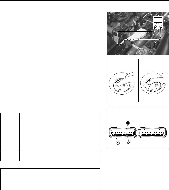
4-74 FI SYSTEM DIAGNOSIS
Step 3 |
|
3 |
|
|
|
|
|
|
|
|
1) Turn the ignition switch OFF. |
|
|
|
|
|
|
|
|
V |
|
2) Connect the STP sensor coupler. |
|
|
|
|
|
|
|
|
|
|
|
|
|
|
|
|
|
|
|
|
|
3) Insert the needle pointed probes to the STP sensor coupler. |
|
|
|
|
|
|
|
|
||
|
|
|
|
|
|
|
|
|||
|
|
|
|
|
|
|
|
|||
4) Disconnect the STVA lead wire coupler. |
|
|
|
|
|
|
|
|
|
|
5) Turn the ignition switch ON. |
|
|
|
|
|
|
|
|
|
|
6) Measure the STP sensor output voltage at the coupler |
|
|
|
|
|
|
|
|
||
(between + Y wire and - B wire) by turning the secondary |
|
|
|
|
|
|
|
|
||
throttle valve (close and open) with a finger. |
|
|
|
|
|
|
|
|
||
STP sensor output voltage |
|
|
|
|
|
|
|
|
|
|
3 |
|
|
3 |
|
|
|
|
|
||
Secondary throttle valve is closed |
: Approx. 0.5 V |
|
|
|
|
|
|
|
|
|
Secondary throttle valve is opened : Approx. 3.9 V |
|
|
|
|
|
|
|
|
||
09900-25008: Multi-circuit tester set |
|
|
|
|
|
|
|
|
|
|
09900-25009: Needle pointed probe set |
|
|
|
|
|
|
|
|
||
Tester knob indication: Voltage ( ) |
|
|
|
|
|
|
|
|
|
|
Is the voltage OK? |
|
|
3 |
E |
|
|
|
• R, Y/W or B/Br wire open or shorted to ground, |
|
ECM couplers (Harness side) |
|||
|
L |
(Gray) |
||||
|
or poor A, J or S connection |
P |
(Black) |
|||
|
|
|
||||
|
|
|
|
|
||
|
• If wire and connection are OK, intermittent trou- |
|
|
|
||
YES |
ble or faulty ECM. |
M |
|
|
|
|
|
|
|
|
|||
|
|
|
|
|
||
|
• Recheck each terminal and wire harness for |
|
|
|
||
|
open circuit and poor connection. |
|
|
|
|
|
|
|
A |
|
|
|
|
|
• Replace the ECM with a known good one, and |
|
|
|
||
|
inspect it again.S |
|
|
|
|
|
NO
If check result is not satisfactory, replace STP sensor with a new one.
When using the multi-circuit tester, do not storongly touch the terminal of the ECM coupler with a needle pointed tester probe to prevent the terminal damage or terminal bend.
After repairing the trouble, clear the DTC using SDS tool. ( 4-27)

|
|
|
|
|
|
FI SYSTEM DIAGNOSIS 4-75 |
||
“C31” (P0705) GP SWITCH CIRCUIT MALFUNCTION |
|
|||||||
|
DETECTED CONDITION |
|
|
POSSIBLE CAUSE |
|
|||
No Gear Position switch voltage |
|
|
• |
Gear Position switch circuit open or short |
|
|||
Switch voltage is not within the following range. |
• |
Gear Position switch malfunction |
|
|||||
Switch voltage > 0.6 V |
|
|
• |
ECM malfunction |
|
|||
|
ECM |
|
|
|
|
Side-stand relay |
|
|
|
|
|
|
To engine stop switch |
|
|||
|
|
|
|
|
|
Ignition |
|
|
|
|
|
BI |
GP switch |
switch |
|
||
|
|
|
N |
|
|
|
||
|
GP |
P |
P |
|
|
|
||
|
6 |
1 |
Neutral indicator |
|
||||
|
E1 |
B/W |
|
|
||||
|
|
|
|
light |
|
|||
|
|
|
|
5 |
|
|
||
|
|
|
B/W |
2 |
|
|
||
|
|
|
4 |
|
|
|||
|
|
|
|
3 |
|
|
||
|
|
|
|
|
|
|
||
|
|
|
|
|
|
Side-stand switch |
|
|
INSPECTION |
|
|
|
|
1 |
|
||
Step 1 |
|
|
|
|
E |
|
||
1) |
Turn the ignition switch OFF. |
|
|
|
L |
|
||
2) |
Lift and support the fuel tank. ( 5-3) |
|
|
|
||||
|
|
|
|
|||||
3) |
Check the GP switch coupler for loose or poor contacts. |
|
||||||
|
If OK, then measure the GP switch voltage. |
P |
|
|||||
|
|
|
M |
|
|
|||
|
|
A |
|
|
|
|||
4) |
|
S |
|
|
|
1 |
|
|
Support the motorcycle with a jack. |
|
|
|
|||||
5) |
Fold the side-stand to up position. |
|
|
|
|
V |
||
6) |
Make sure the engine stop switch is in the “RUN” position. |
|||||||
|
||||||||
7) |
Insert the needle pointed probe to the lead wire coupler. |
|
||||||
8) |
Turn the ignition switch ON. |
|
|
|
|
|
||
9) |
Measure the voltage at the wire side coupler between P wire |
|
||||||
|
and B/W wire, when shifting the gearshift lever from 1st to |
|
||||||
|
Top. |
|
|
|
|
|
|
|
GP switch voltage: 0.6 V and more (+ P – - B/W)
09900-25008: Multi-circuit tester set
09900-25009: Needle pointed probe set
Tester knob indication: Voltage ( )

4-76 FI SYSTEM DIAGNOSIS |
|
|
|
Is the voltage OK? |
1 |
|
|
|
• P wire open or shorted to ground |
ECM couplers (Harness side) |
|
|
(Black) |
(Gray) |
|
|
• If wire and connection are OK, intermittent trou- |
||
|
|
|
|
|
ble or faulty ECM. |
|
|
YES |
• Recheck each terminal and wire harness for |
|
|
|
open circuit and poor connection. |
|
|
|
• Replace the ECM with a known good one, and |
|
|
|
inspect it again. |
|
|
|
• P or B/W wire open, or P wire shorted to ground |
|
|
|
• Loose or poor contacts on the ECM coupler |
|
|
NO |
(terminal M or X) |
|
|
|
• If wire and connection are OK, replace the GP |
|
|
|
switch with a new one. |
|
|
|
|
|
|
When using the multi-circuit tester, do not storongly |
|
|
|
touch the terminal of the ECM coupler with a needle |
|
E |
|
pointed tester probe to prevent the terminal damage |
|
||
or terminal bend. |
|
|
|
|
|
|
|
|
|
|
|
10)After repairing the trouble, clear the DTC using SDS tool. |
|
||
( 4-27) |
P |
||
M |
L |
||
|
|
||
|
A |
|
|
|
S |
|
|

FI SYSTEM DIAGNOSIS 4-77
“C32” (P0201), “C33” (P0202), “C34” (P0203) or “C35” (P0204) PRIMARY FUEL INJECTOR CIRCUIT MALFUNCTION
DETECTED CONDITION |
|
POSSIBLE CAUSE |
|
CKP signal is produced but fuel injector signal is |
• |
Injector circuit open or short |
|
interrupted by 4 times or more continuously. |
• |
Injector malfunction |
|
|
|
• |
ECM malfunction |
ECM |
|
|
Fuel pump relay |
|
|
|
|
|
|
|
Y/R |
#11 |
Gr/W |
|
To engine |
|
stop switch |
||
#21 |
Gr/B |
|
|
#31 |
Gr/Y |
|
|
#41 |
Gr/R |
|
|
|
#4 |
#3 |
#2 |
#1 |
E |
|||
|
|
Primary fuel injector |
|
|||||
|
|
|
|
|
|
|
||
|
|
|
|
|
|
|
|
|
|
|
|
|
|
|
|
|
|
INSPECTION |
|
|
L |
|
||||
|
|
|
1 |
|
||||
Step 1 |
|
|
|
|
|
|
|
|
1) |
Turn the ignition switch OFF. |
M |
|
|
|
|
|
|
|
|
|
|
|
|
|
||
2) |
Lift and support the fuel tank ( 5-3) |
P |
|
|
|
|
||
3) |
Check the injector coupler for loose or poor contacts. |
|
|
|
|
|
||
|
A |
|
|
|
|
|
|
|
|
If OK, then measure the injector resistance. |
|
|
|
|
|
|
|
|
S |
|
|
|
|
|
|
|
4) |
Disconnect the injector coupler and measure the resistance |
|
|
1 |
|
|||
|
between terminals. |
|
|
|
|
|
|
|
Injector resistance: 11 – 13 Ω at 20 °C (68 °F)
(Terminal – Terminal)

4-78 FI SYSTEM DIAGNOSIS
5) If OK, then check the continuity between each terminal and |
1 |
|
ground. |
|
|
Injector continuity: |
∞ Ω (Infinity) |
|
09900-25008: Multi-circuit tester set
Tester knob indication: Resistance (Ω)
Are the resistance and continuity OK?
YES |
Go to Step 2. |
|
|
NO |
Replace the injector with a new one. ( 5-23) |
6)After repairing the trouble, clear the DTC using SDS tool. ( 4-27)
Step 2 |
|
|
|
2 |
|
|
|
|
|
|
1) Turn the ignition switch ON. |
|
|
|
|
|
|
|
|
|
|
2) Measure the injector voltage between Y/R wire and ground. |
|
|
|
|
|
V |
|
|||
Injector voltage: Battery voltage |
|
|
|
|
E |
|
|
|
|
|
|
|
|
|
|
|
|
|
|
||
(+ Y/R – - Ground) |
|
|
|
|
|
|
|
|
||
|
L |
|||||||||
NOTE: |
|
|
||||||||
|
|
|
|
|
|
|
|
|
|
|
Injector voltage can be detected only 3 for seconds after ignition |
|
|
|
|
|
|
|
|
||
switch is turned ON. |
|
P |
||||||||
|
|
|
|
|
|
|
|
|
|
|
09900-25008: Multi-circuit tester set |
M |
|
|
|
|
|
|
|
|
|
Tester knob indication: Voltage ( ) |
|
|
|
|
|
|
|
|
||
A |
|
|
|
|
|
|
|
|
|
|
S |
|
|
|
|
|
|
|
|
|
|
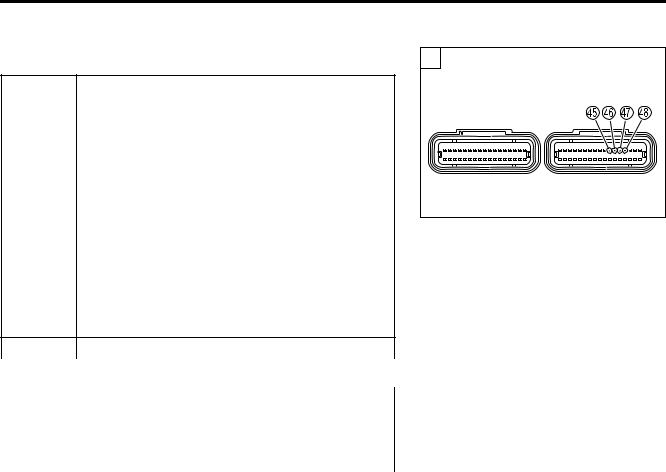
FI SYSTEM DIAGNOSIS 4-79
Is the voltage OK? |
2 |
|
|
• Gr/W wire open or shorted to ground, or poor h |
ECM couplers (Harness side) |
||
(Black) |
(Gray) |
||
connection (#1 cylinder side) |
|||
|
|
||
• Gr/B wire open or shorted to ground, or poor g |
|
|
|
connection (#2 cylinder side) |
|
|
|
• Gr/Y wire open or shorted to ground, or poor f |
|
|
|
connection (#3 cylinder side) |
|
|
|
• Gr/R wire open or shorted to ground, or poor e |
|
|
|
YES |
|
|
|
connection (#4 cylinder side) |
|
|
|
•If wire and connection are OK, intermittent trouble or faulty ECM.
•Recheck each terminal and wire harness for open circuit and poor connection.
•Replace the ECM with a known good one, and inspect it again.
NO |
Open circuit in the Y/R wire |
|
||
|
|
|
|
E |
|
|
|
|
|
When using the multi-circuit tester, do not storongly |
|
|||
|
|
|||
touch the terminal of the ECM coupler with a needle |
|
|
||
pointed tester probe to prevent the terminal damage |
|
|
||
or terminal bend. |
P |
|
|
|
L |
||||
|
|
M |
|
|
3) After repairing the trouble, clear the DTC using SDS tool. |
|
|||
( 4-27) |
A |
|
||
|
|
|
||
|
|
S |
|
|
4-80 FI SYSTEM DIAGNOSIS
“C36” (P1764), “C37” (P1765), “C38” (P1766) or “C39” (P1767) SECONDARY FUEL INJECTOR CIRCUIT MALFUNCTION
DETECTED CONDITION |
|
POSSIBLE CAUSE |
|
Some failure exists in the fuel injector signal in a |
• |
Injector circuit open or short |
|
high load, high revolution condition. |
• |
Injector malfunction |
|
|
|
• |
ECM malfunction |
ECM |
|
|
Fuel pump relay |
|
|
|
|
|
|
|
Y/R |
#12 |
Lg |
|
To engine |
|
stop switch |
||
#22 |
Lg/W |
|
|
#32 |
Lg/G |
|
|
#42 |
Lg/BI |
|
|
|
#4 |
#3 |
#2 |
#1 |
|
|
|
E |
|
Secondary fuel injector |
|
|
|
||||
|
|
|
|
|
||||
|
|
|
|
|
|
|
|
|
|
|
|
|
|
|
|
|
|
INSPECTION |
|
|
|
L |
||||
|
|
|
1 |
|
||||
Step 1 |
|
|
|
|
|
|
|
|
1) |
Turn the ignition switch OFF. |
|
M |
|
|
|
|
|
|
Lift and support the fuel tank. ( 5-3) |
|
|
|
|
|
||
2) |
|
|
P |
|
||||
3) |
Check the injector coupler for loose or poor contacts. |
|
|
|
|
|
||
|
A |
|
|
|
|
|
||
|
If OK, then measure the injector resistance. |
|
|
|
|
|
||
|
S |
|
|
|
|
|
|
|
4) |
Disconnect the injector coupler and measure the resistance |
|
|
1 |
|
|||
|
between terminals. |
|
|
|
|
|
|
|
Injector resistance: 11 – 13 Ω at 20 °C (68 °F)
(Terminal – Terminal)

FI SYSTEM DIAGNOSIS 4-81
5) If OK, then check the continuity between each terminal and |
1 |
|
ground. |
|
|
Injector continuity: |
∞ Ω (Infinity) |
|
09900-25008: Multi-circuit tester set
Tester knob indication: Resistance (Ω)
Are the resistance and continuity OK?
YES |
Go to Step 2. |
|
|
NO |
Replace the injector with a new one. ( 5-23) |
6)After repairing the trouble, clear the DTC using SDS tool. ( 4-27)
Step 2 |
|
|
2 |
|
|
|
|
|
|
|
1) Turn the ignition switch ON. |
|
|
|
|
|
|
V |
|
||
2) Measure the injector voltage between Y/R wire and ground. |
|
|
|
|
|
|
||||
|
|
|
|
|
|
|
|
|||
|
|
|
|
|
|
|
|
|||
Injector voltage: Battery voltage |
|
|
|
|
|
|
|
|
|
|
|
|
|
|
|
|
|
|
|
||
|
E |
|||||||||
(+ Y/R – - Ground) |
|
|||||||||
L |
||||||||||
NOTE: |
||||||||||
|
|
|
|
|
|
|
|
|
||
Injector voltage can be detected only 3 seconds after ignition |
|
|
|
|
|
|
|
|
||
switch is turned ON. |
P |
|
|
|
|
|
|
|
|
|
|
|
|
|
|
|
|
|
|
||
09900-25008: Multi-circuit tester set |
|
|
|
|
|
|
|
|
|
|
M |
|
|
|
|
|
|
|
|
||
Tester knob indication: Voltage ( ) |
|
|
|
|
|
|
|
|
|
|
A |
|
|
|
|
|
|
|
|
|
|
S |
|
|
|
|
|
|
|
|
|
|

4-82 FI SYSTEM DIAGNOSIS |
|
|
Is the voltage OK? |
2 |
|
• Lg wire open or shorted to ground, or poor x |
ECM couplers (Harness side) |
|
connection (#1 cylinder side) |
(Black) |
(Gray) |
|
|
|
• Lg/W wire open or shorted to ground, or poor w |
|
|
connection (#2 cylinder side) |
|
|
• Lg/G wire open or shorted to ground, or poor v |
|
|
connection (#3 cylinder side) |
|
|
• Lg/BI wire open or shorted to ground, or poor u |
|
|
YES |
|
|
connection (#4 cylinder side) |
|
|
•If wire and connection are OK, intermittent trouble or faulty ECM.
•Recheck each terminal and wire harness for open circuit and poor connection.
•Replace the ECM with a known good one, and inspect it again.
NO |
Open circuit in the Y/R wire. |
|
||
|
|
|
|
E |
|
|
|
|
|
When using the multi-circuit tester, do not storongly |
|
|||
|
|
|||
touch the terminal of the ECM coupler with a needle |
|
|
||
pointed tester probe to prevent the terminal damage |
|
|
||
or terminal bend. |
P |
|||
|
|
L |
||
|
|
M |
|
|
3) After repairing the trouble, clear the DTC using SDS tool. |
|
|||
( 4-27) |
A |
|
||
|
|
|
||
|
|
S |
|
|

|
|
|
|
|
|
|
|
|
|
|
|
|
|
|
|
|
|
|
|
|
|
|
|
|
|
|
|
|
|
|
|
|
|
|
|
|
FI SYSTEM DIAGNOSIS 4-83 |
|||||||||
“C41” (P0230-H/L) FP RELAY CIRCUIT MALFUNCTION |
|
|
|
|
|
|
|
|
|
|
||||||||||||||||||||||||||||||||||||
|
|
|
|
|
|
|
|
|
|
|
|
|
|
|
|
|
|
|
|
|
|
|
|
|
|
|
|
|
|
|
|
|
|
|
|
|
|
|
|
|
|
|
|
|
|
|
|
|
|
|
DETECTED CONDITION |
|
|
|
|
|
|
|
POSSIBLE CAUSE |
||||||||||||||||||||||||||||||||||
|
|
|
|
|
|
|
|
|
|
|
|
|
|
|
|
|
|
|
|
|
|
|
|
|
|
|
|
|
|
|
|
|
|
|
|
|
|
|
|
|
|
|||||
C41 |
|
No voltage is applied to fuel pump |
|
|
|
• Fuel pump relay circuit open or short |
||||||||||||||||||||||||||||||||||||||||
|
|
|
|
although fuel pump relay is turned ON, |
• Fuel pump relay malfunction |
|||||||||||||||||||||||||||||||||||||||||
|
|
|
|
or voltage is applied to fuel pump, |
|
|
|
• ECM malfunction |
|
|
|
|
|
|
|
|
|
|
||||||||||||||||||||||||||||
|
|
|
|
although fuel pump relay is turned OFF. |
|
|
|
|
|
|
|
|
|
|
|
|
|
|
|
|
|
|
|
|
||||||||||||||||||||||
|
|
|
|
|
|
|
|
|
|
|
|
|
|
|
|
|
|
|
|
|
|
|
|
|
|
|
|
|
|
|
|
|
|
|
|
|
|
|
|
|
|
|
||||
P0230 |
|
|
Voltage is applied to fuel pump although |
• Fuel pump relay switch circuit shorted to power |
||||||||||||||||||||||||||||||||||||||||||
|
|
H |
fuel pump relay is turned OFF. |
|
|
|
source |
|
|
|
|
|
|
|
|
|
|
|
|
|
|
|
|
|
|
|
||||||||||||||||||||
|
|
|
|
|
|
|
|
|
|
|
|
|
|
|
|
|
|
|
|
|
|
|
|
|
|
|
• Faulty fuel pump relay (switch side) |
|||||||||||||||||||
|
|
L |
|
No voltage is applied to fuel pump |
|
|
|
• Fuel pump relay coil circuit open or short |
||||||||||||||||||||||||||||||||||||||
|
|
|
although fuel pump relay is turned ON. |
• Faulty fuel pump relay (coil side) |
||||||||||||||||||||||||||||||||||||||||||
|
|
|
|
|||||||||||||||||||||||||||||||||||||||||||
|
|
|
|
|
|
|
|
|
|
|
|
|
|
|
|
|
|
|
|
|
|
|
|
|
|
|
|
|
|
|
|
|
|
|
|
|
|
|
|
|
|
|
|
|
|
|
|
|
|
|
|
|
|
|
|
|
|
|
|
|
|
|
|
|
|
|
|
|
|
|
|
|
|
|
|
|
|
|
|
|
|
|
|
|
|
|
|
|
|
|
|
||
|
|
ECM |
|
|
|
|
|
|
|
|
|
|
|
|
|
|
|
|
|
|
|
|
|
|
|
|
|
|
|
|
|
|
|
|
|
|
|
|
|
|
|
|
|
|
||
|
|
|
|
|
|
|
|
|
|
|
|
|
|
|
M |
|
Fuel pump |
|
|
|
|
|
|
|
|
|
|
|
|
|
|
|
|
|
|
|
|
|
|
|
||||||
|
|
|
|
|
|
|
|
|
|
|
|
|
|
|
|
|
|
|
|
|
|
|
|
|
|
|
Engine stop |
|
|
|
|
|
|
|
|
|
|
|
|
|
|
|
|
|
|
|
|
|
|
|
|
|
|
|
|
|
|
|
|
|
|
|
|
|
|
|
|
|
|
|
|
|
|
|
|
|
|
|
|
|
|
|
|
|
|
|
|
|
|
|
|
||
|
|
|
|
|
|
|
|
|
|
|
|
|
|
|
|
|
|
|
|
|
|
|
|
|
|
|
switch |
|
|
|
|
|
|
|
|
|
|
|
|
|
|
|
|
|
|
|
|
|
|
|
|
|
|
|
|
|
|
|
|
|
|
|
|
|
|
|
|
|
|
|
|
|
|
|
|
|
|
|
|
|
|
|
|
|
|
|
|
|
|
|
|||
|
|
|
|
|
|
|
|
|
|
|
|
|
|
|
|
|
|
|
|
|
|
|
|
|
|
|
|
|
E |
|
|
|
|
|
|
|
|
|
|
|||||||
|
|
VM |
|
|
|
|
|
|
|
|
|
|
|
|
|
|
|
|
|
|
|
|
|
|
|
To side-stand |
|
|
|
|
|
|
|
|
|
Ignition |
|
|
|
|
|
|||||
|
|
|
|
|
Y/R |
|
|
|
|
|
|
|
R/BI |
|
|
switch |
|
Side-stand |
|
switch |
|
|
|
|
|
|
||||||||||||||||||||
|
|
|
|
|
|
|
|
|
|
|
|
|
|
|
|
|
||||||||||||||||||||||||||||||
|
|
FP Relay |
|
|
|
|
|
|
|
|
|
|
|
|
|
|
|
|
|
|
|
|
|
|
|
|
|
|
|
|||||||||||||||||
|
|
|
|
|
|
|
|
|
|
|
|
|
|
|
|
|
|
|
|
|
|
|
|
|
|
|
|
|
|
|||||||||||||||||
|
|
|
|
Y/B |
|
|
|
|
|
|
|
O/W |
|
|
|
relay |
|
|
|
|
|
|
|
|
|
|
||||||||||||||||||||
|
|
|
|
|
|
|
|
|
|
|
|
|
|
|
|
|
|
|
|
|||||||||||||||||||||||||||
|
|
|
|
|
|
|
|
|
|
|
|
|
|
|
|
|
|
|
|
|
|
|
|
|
|
|
|
|
|
|
|
|
|
|
|
|
|
|
|
|
|
|
|
|
|
|
|
|
|
|
|
|
|
|
|
|
|
|
|
|
|
|
|
|
|
|
|
|
|
|
P |
|
|
|
|
|
|
|
|
|
|
|
|
|
|
|
|
|
|
|
|||
|
|
|
|
|
|
|
|
|
|
|
|
|
|
|
|
|
|
|
|
|
|
|
|
|
|
|
|
|
|
|
|
|
|
|
|
|
|
|
|
|
|
|
||||
|
|
|
|
|
|
|
|
|
|
|
|
|
|
|
|
|
|
|
Fuel pump |
|
|
|
|
|
|
|
|
|
|
|
|
|
|
|
|
|
|
|
||||||||
|
|
|
|
|
|
|
|
|
|
|
|
|
|
|
|
|
|
|
|
|
|
L |
|
|
|
|
|
|
|
|
|
|
||||||||||||||
|
|
|
|
|
|
|
|
|
|
|
|
|
|
|
|
|
|
|
relay |
|
|
|
|
|
|
|
|
|
|
|
|
|
||||||||||||||
|
|
|
|
|
|
|
|
|
|
|
|
|
|
|
|
|
|
|
|
|
|
|
|
|
|
|
|
|
|
|
|
|||||||||||||||
|
|
|
|
|
|
|
|
|
|
|
|
|
|
|
|
|
|
|
|
M |
|
|
|
|
|
|
|
|
|
|
|
|
|
|
|
|
|
|
|
|||||||
|
|
|
|
|
|
|
|
|
|
|
|
|
|
|
|
|
|
|
|
|
|
|
|
|
|
|
|
|
|
|
|
|
|
|
|
|
|
|
||||||||
|
|
|
|
|
|
|
|
|
|
|
|
|
|
|
|
|
|
|
|
|
|
|
|
|
|
|
|
|
|
|
|
|
|
|
|
|
|
|
||||||||
INSPECTION |
|
|
|
|
|
|
|
A |
|
|
|
|
|
1 |
|
|
|
|
|
|
|
|
|
|
|
|
|
|
|
|||||||||||||||||
Step 1 (When indicating C41:) |
|
|
|
|
|
|
|
|
|
|
|
|
|
|
|
|
|
|
|
|
|
|
|
|
|
|
|
|
|
|||||||||||||||||
1) Turn the ignition switch OFF. |
|
|
|
|
|
|
|
|
|
|
|
|
|
|
|
|
|
|
|
|
|
|
|
|
|
|
|
|
|
|||||||||||||||||
2) Lift and support the fuel tank. ( 5-3) |
|
|
|
|
|
|
|
|
|
|
|
|
|
|
|
|
|
|
|
|
|
|
|
|||||||||||||||||||||||
3) Check the FP relayScoupler for loose or poor contacts. |
|
|
|
|
|
|
|
|
|
|
|
|
|
|
|
|
|
|
|
|||||||||||||||||||||||||||
If OK, then check the FP relay. ( 5-7) |
|
|
|
|
|
|
|
|
|
|
|
|
|
|
|
|
|
|
|
|
|
|
|
|||||||||||||||||||||||

4-84 FI SYSTEM DIAGNOSIS |
|
|
|
Is the FP relay OK? |
1 |
|
|
• Y/B or O/W wire open or short or poor ] con- |
ECM couplers (Harness side) |
||
(Black) |
(Gray) |
||
nection |
|||
|
|
||
• Y/R or R/Bl wire open, shorted or poor W con- |
|
|
|
nection |
|
|
|
• If wire and connection are OK, intermittent trou- |
|
|
|
YES |
|
|
|
ble or faulty ECM. |
|
|
|
• Recheck each terminal and wire harness for |
|
|
|
open circuit and poor connection. |
|
|
|
•Replace the ECM with a known good one, and inspect it again.
NO |
Replace the FP relay with a new one. |
|
When using the multi-circuit tester, do not storongly |
|
|
|
|
|
|
touch the terminal of the ECM coupler with a needle |
|
|
|
|
|
|
pointed tester probe to prevent the terminal damage |
|
|
|
E |
|
|
or terminal bend. |
|
|
|
|
|
|
|
|
|
|
||
4) |
After repairing the trouble, clear the DTC using SDS tool. |
|
|
|||
|
( 4-27) |
|
|
|
|
|
|
|
|
L |
|||
|
|
|
|
|||
Step 1 (When indicating P0230-H:) |
P |
|
|
|||
1 |
|
|||||
1) |
Turn the ignition switch OFF. |
|
||||
|
|
|||||
M |
|
|
|
|||
2) |
Lift and support the fuel tank. ( 5-3) |
|
|
|
||
3) |
|
|
|
|
||
Check the FP relay coupler for loose or poor contacts. |
|
|
|
|||
|
If OK, then check the FP relay. ( 5-7) |
|
|
|
|
|
|
A |
|
|
|
||
|
S |
|
|
|
|
|
Is the FP relay OK? |
1 |
|
|
• Y/R wire shorted to power source |
ECM couplers (Harness side) |
||
(Black) |
(Gray) |
||
• Y/B wire shorted to ground |
|||
|
|
||
• If wire and connection are OK, intermittent trou- |
|
|
|
ble or faulty ECM. |
|
|
|
YES |
|
|
|
• Recheck each terminal and wire harness for |
|
|
|
open circuit and poor connection. |
|
|
|
• Replace the ECM with a known good one, and |
|
|
|
inspect it again. |
|
|
|
NO |
Replace the FP relay with a new one. |
4)After repairing the trouble, clear the DTC using SDS tool. ( 4-27)

FI SYSTEM DIAGNOSIS 4-85
Step 1 (When indicating P0230-L:) |
1 |
1)Turn the ignition switch OFF.
2)Lift and support the fuel tank. ( 5-3)
3)Check the FP relay coupler for loose or poor contacts. If OK, then check the FP relay. ( 5-7)
Is the FP relay OK? |
|
1 |
|
|
|
|
|
|
ECM couplers (Harness side) |
||
• Y/B wire open or poor ] connection |
|||||
|
|
(Black) |
(Gray) |
||
|
|
|
|||
•O/W wire open or shorted to ground
•R/BI or Y/R wire open or shorted to ground or
|
|
poor W connection |
|
|
|
|
|
|
|
YES |
• If wire and connection are OK, intermittent trou- |
|
|
|
|
||||
|
|
|
|
||||||
|
ble or faulty ECM. |
|
|
|
|
|
|
|
|
|
|
|
|
|
E |
||||
|
• Recheck each terminal and wire harness for |
||||||||
|
|
open circuit and poor connection. |
|
|
|
||||
|
|
|
|
|
|
|
|
|
|
|
• Replace the ECM with a known good one, and |
|
|
|
|
||||
|
|
inspect it again. |
|
|
|
|
|
|
|
|
|
|
|
|
|
|
|
|
|
NO |
|
|
P |
|
|
|
|
||
Replace the FP relay with a new one. |
L |
||||||||
|
|
|
|
|
|
||||
4) After repairing the trouble, clear the DTC using SDS tool. |
|
|
|
|
|||||
( 4-27) |
M |
|
|
|
|
|
|
||
|
|
A |
|
|
|
|
|
|
|
|
|
S |
|
|
|
|
|
|
|

4-86 FI SYSTEM DIAGNOSIS
“C42” (P01650) IG SWITCH CIRCUIT MALFUNCTION
DETECTED CONDITION |
|
POSSIBLE CAUSE |
|
|
|
Ignition switch signal is not input to the ECM. |
• |
Ignition system circuit open or short |
|
• |
ECM malfunction |
|
|
|
When the ID agreement is not verified. |
• |
Immobilizer system malfunction |
ECM does not receive communication signal from the |
|
(For E-02, 19, 24) |
immobilizer antenna. |
|
|
(For E-02, 19, 24) |
|
|
INSPECTION
* Refer to the IGNITION SWITCH INSPECTION for details. ( 9-39)
E
L
P
M
A
S

FI SYSTEM DIAGNOSIS 4-87
“C44” (P0130/P0135) HO2 SENSOR (HO2S) CIRCUIT MALFUNCTION
(For E-02, 19)
|
|
DETECTED CONDITION |
|
|
|
|
|
|
|
|
|
|
|
|
|
POSSIBLE CAUSE |
|||||||||||||||||||||||||||
C44 |
HO2 sensor output voltage is not input |
|
• HO2 sensor circuit open or shorted to ground. |
||||||||||||||||||||||||||||||||||||||||
(P0130) |
to ECM during engine operation and |
|
|
|
|
|
|
• |
Fuel system malfunction. |
|
|
|
|
|
|
|
|
|
|
||||||||||||||||||||||||
|
|
running condition. |
|
|
|
|
|
|
• |
ECM malfunction. |
|
|
|
|
|
|
|
|
|
|
|||||||||||||||||||||||
|
|
(Sensor voltage < 0.55 V) |
|
|
|
|
|
|
|
|
|
|
|
|
|
|
|
|
|
|
|
|
|
|
|
|
|
|
|
||||||||||||||
|
|
|
|
|
|
|
|
|
|
|
|
|
|
|
|
|
|
|
|
|
|
• Battery voltage supply to the HO2 sensor. |
|||||||||||||||||||||
C44 |
The heater can not operate so that |
|
|
|
|
|
|
||||||||||||||||||||||||||||||||||||
(P0135) |
heater operation voltage is not supplied |
|
|
|
|
|
|
|
|
|
|
|
|
|
|
|
|
|
|
|
|
|
|
||||||||||||||||||||
|
|
to the oxygen heater circuit. |
|
|
|
|
|
|
|
|
|
|
|
|
|
|
|
|
|
|
|
|
|
|
|
|
|
|
|
||||||||||||||
|
|
|
|
|
|
|
|
|
|
|
|
|
|
|
|
|
|
|
|
|
|
|
|
|
|
|
|
|
|
|
|
|
|
|
|
|
|
|
|
|
|
|
|
|
|
|
|
|
|
|
|
|
|
|
|
|
|
|
|
|
|
|
|
|
|
|
|
|
|
|
|
|
|
|
|
|
|
|
|
|
|
|
|
|
|
|
|
|
|
ECM |
|
|
|
|
|
|
|
|
|
|
|
|
|
|
|
|
|
|
|
|
|
|
|
|
|
|
|
|
|
|
|
|
|
|
|
|
|
|
|
|
|
|
|
|
|
|
|
|
|
|
|
|
|
|
|
|
|
|
|
|
|
|
|
|
|
|
Engine stop |
Side-stand |
|
Ignition |
|||||||||||||||
|
|
E2 |
|
|
|
B/Br |
|
|
|
|
|
|
|
|
|
|
|
|
|
|
|
|
|
|
|||||||||||||||||||
|
|
|
|
|
|
|
|
|
|
|
|
|
|
switch |
relay |
|
switch |
||||||||||||||||||||||||||
|
|
OX |
|
|
|
|
|
|
|
|
|
|
|
|
|
|
|
|
|
|
|
|
|
|
|
||||||||||||||||||
|
|
|
|
|
W/G |
|
|
|
|
|
|
|
|
|
|
|
|
|
|
|
|
|
|
|
|
|
|
|
|
|
|
|
|
||||||||||
|
|
OXH |
|
|
|
|
|
|
|
|
|
|
|
|
|
|
|
|
|
|
|
O/W |
|
|
|
|
|
|
|
|
|
|
|
|
|
|
|
|
|
|
|
||
|
|
|
|
|
|
|
|
|
|
|
|
|
|
|
|
|
|
|
|
|
|
|
|
|
|
|
|
|
|
|
|
|
|
|
|
|
|
|
|||||
|
|
|
|
|
|
|
|
|
|
|
|
|
|
|
|
|
|
|
|
|
|
|
|
|
|
|
|
|
|
|
|
|
|||||||||||
|
|
|
|
|
W/B |
|
|
|
|
|
|
|
|
To GP |
|
|
|
|
|
|
|
|
|
|
|
|
|
|
|
|
|||||||||||||
|
|
|
|
|
|
|
|
|
|
|
|
|
|
|
|
|
|
|
|
|
|
|
|
|
|
|
|
|
|
||||||||||||||
|
|
|
|
|
|
|
|
|
|
|
|
|
|
|
|
|
|
|
|
|
|
|
|
|
switch |
|
|
|
|
|
|
|
|
|
|
|
|
|
|
|
|
||
|
|
|
|
|
|
|
|
|
|
|
|
|
|
|
|
|
|
|
|
|
|
|
|
|
|
E |
|
|
|
|
|
|
|
|
|
|
|||||||
|
|
|
|
|
|
|
|
|
|
|
|
|
|
Gr |
|
|
|
|
|
|
|
|
|
|
|
|
|
|
|
|
|
|
|
|
|||||||||
|
|
|
|
|
|
|
|
|
|
|
W B |
|
W |
|
|
|
L |
|
|
|
|
|
|
|
|
|
|
||||||||||||||||
|
|
|
|
|
|
|
|
|
|
|
|
|
|
|
|
|
|
|
|
|
|
|
|
|
|
|
|
|
|
|
|
|
|
|
|||||||||
|
|
|
|
|
|
|
|
|
|
|
|
|
|
|
|
|
|
|
|
|
|
|
|
|
|
|
|
|
|
|
|
|
|
||||||||||
|
|
|
|
|
|
|
|
|
|
|
|
|
|
|
|
|
|
|
|
|
|
|
|
|
|
|
|
|
|
|
|
|
|
|
|||||||||
|
|
|
|
|
|
|
|
|
|
|
|
|
|
|
|
|
|
|
|
|
|
HO2 sensor |
|
|
|
|
|
|
|
|
|
|
|
|
|
|
|
|
|||||
|
|
|
|
|
|
|
|
|
|
|
|
|
|
|
|
|
|
|
|
|
|
|
|
|
|
|
|
|
|
|
|
|
|
|
|
|
|
||||||
|
|
|
|
|
|
|
|
|
|
|
|
|
|
|
|
|
|
|
|
|
|
|
|
|
|
|
|
|
|
|
|
|
|
|
|
|
|
||||||
|
|
|
|
|
|
|
|
|
|
|
|
|
|
|
|
|
|
|
|
P |
|
|
|
|
|
|
|
|
|
|
|
|
|
|
|
|
|||||||
|
|
|
|
|
|
|
|
|
|
|
|
|
|
|
|
|
|
|
|
|
|
|
|
|
|
|
|
|
|
|
|
|
|
|
|
||||||||
|
|
|
|
|
|
|
|
M |
|
|
|
|
|
|
|
|
|
|
|
|
|
|
|
|
|
|
|
|
|||||||||||||||
INSPECTION |
|
|
|
|
|
|
|
|
|
1 |
|
|
|
|
|
|
|
|
|
|
|
|
|
|
|||||||||||||||||||
|
|
|
A |
|
|
|
|
|
|
|
|
|
|
|
|
|
|
|
|
|
|
|
|
|
|
|
|
|
|||||||||||||||
|
|
|
|
|
|
|
|
|
|
|
|
|
|
|
|
|
|
|
|
|
|
|
|
|
|
|
|
|
|
|
|
|
|||||||||||
Step 1 (When indicating C44/P0130:) |
|
|
|
|
|
|
|
|
|
|
|
|
|
|
|
|
|
|
|
|
|
|
|
|
|
|
|
||||||||||||||||
1) Turn the ignition switch OFF. |
|
|
|
|
|
|
|
|
|
|
|
|
|
|
|
|
|
|
|
|
|
|
|
|
|
|
|
||||||||||||||||
|
|
|
S |
|
|
|
|
|
|
|
|
|
|
|
|
|
|
|
|
|
|
|
|
|
|
|
|
|
|
|
|||||||||||||
2) Lift and support the fuel tank. ( 5-3)
3) Check the HO2 sensor for loose or poor contacts.
If OK, then check the HO2 sensor lead wire continuity.
4) |
Disconnect the HO2 sensor coupler |
1 |
|
|
|
! |
|||||
5) |
Check the continuity between W/G wire A and ground. |
|
|||
|
|||||
6)Also, check the continuity between W/G wire A and B/Br wire B. If the sound is not heard from the tester, the circuit condition is OK.
09900-25008: Multi-circuit tester set
Tester knob indication: Continuity test ( )
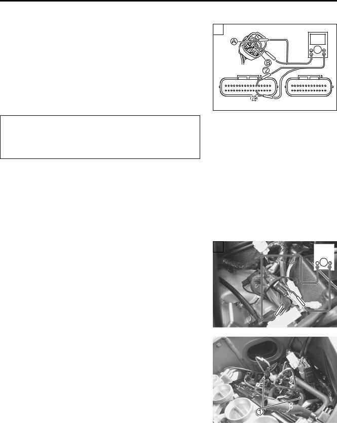


 MO
MO 
 VCC
VCC  MPS E2


4-96 FI SYSTEM DIAGNOSIS
Step 4 |
4 |
|
|
|
|
|
1) |
Turn the ignition switch OFF. |
|
|
|
|
|
|
|
|
|
|
||
2) |
Connect the position sensor coupler. |
|
|
|
|
|
3) |
Measure the position sensor output voltage at fully close posi- |
|
|
|
|
|
|
tion and fully open position. |
|
|
|
|
|
4) |
Insert the needle pointed probes to the back side of the posi- |
|
|
|
|
|
|
|
|
|
|
||
|
|
|
|
|
||
|
tion sensor lead wire coupler. (+ Y – - B/Br) |
|
|
|
12 V |
|
5)Disconnect the EXCVA motor lead wire coupler 2.
6)To set the EXCV to fully close position, apply 12 V to A and
B terminals. |
|
|
|
|
|
|
|
|
|
|
|
|
|
|
|
|
Positive wire – A (P wire) terminal |
|
|
|
|
4 |
|
|
|
|
|
|
|
|
|
|
|
Negative wire – B (Gr wire) terminal |
|
|
|
|
|
|
|
|
|
|
|
|
|
|
|
|
7) Turn the ignition switch ON. |
|
|
|
|
|
|
|
|
|
|
|
|
|
|
|
|
8) Measure the position sensor output voltage at fully close posi- |
|
|
|
|
|
|
|
|
|
V |
|
|||||
tion. |
|
|
|
|
|
|
|
|
|
|
|
|
|
|
|
|
|
|
|
|
|
|
|
|
|
|
|
|
|
|
|
|
|
9) Then, to set the EXCV to fully open position, apply 12 V to B |
|
|
|
|
|
|
|
|
|
|
|
|
||||
|
|
|
|
|
|
|
|
|
|
|
|
|||||
and A terminals. |
|
|
|
|
|
|
|
|
|
|
|
|
|
|
|
|
Positive wire – B (Gr wire) terminal |
|
|
|
|
|
E |
||||||||||
Negative wire – A (P wire) terminal |
|
|
|
|
|
|||||||||||
10)Measure the position sensor output voltage at fully open |
|
|
||||||||||||||
position. |
|
|
P |
|
||||||||||||
Position sensor output voltage |
|
|
|
|
|
|
|
|||||||||
|
|
|
|
|
|
|
|
|
|
|
|
|||||
|
|
|
L4 |
|||||||||||||
EXCV is fully close: 0.45 – 1.40 V |
M |
|
|
|
|
|
|
|
|
|
|
|
|
|||
EXCV is fully open: 3.60 – 4.55 V |
|
|
|
|
|
|
|
|
|
|
|
|
||||
|
|
|
|
|
|
|
|
|
|
|
|
|
|
|
||
|
(+ Y – - W) |
|
|
|
|
|
|
|
|
|
|
|
|
|
|
|
09900-25008: Multi circuit tester set |
|
|
|
|
|
|
|
|
|
|
|
|
|
|
|
|
|
S |
|
|
|
|
|
|
|
|
|
|
|
|
|
|
|
|
|
|
|
|
|
|
|
|
|
|
|
|
|
|
|
|
09900-25009: Needle pointed probe set |
|
|
|
|
|
|
|
|
|
|
|
|
|
|
||
|
|
|
|
|
|
12 V |
|
|
|
|
|
|
||||
|
A |
|
|
|
|
|
|
|
||||||||
Tester knob indication: Voltage ( ) |
|
|
|
|
|
|
|
|
|
|
|
|
|
|
|
|
Is the voltage OK? |
|
|
|
|
|
|
|
|
|
|
|
|
|
|
|
|
|
|
|
|
|
|
|
|
|
|
|
|
|
|
|
||
YES |
Replace the ECM with a known good one, and |
|
|
|
|
|
|
|
|
|
|
|
|
|
||
inspect it again. |
|
|
|
|
|
|
|
|
|
|
|
|
|
|
|
|
|
|
|
|
|
|
|
|
|
|
|
|
|
|
|
|
|
|
|
|
|
|
|
|
|
|
|
|
|
|
|
|
|
|
NO |
Go to Step 5. |
|
|
|
|
|
|
|
|
|
|
|
|
|
|
|
11)After repairing the trouble, clear the DTC using SDS tool. ( 4-27)

FI SYSTEM DIAGNOSIS 4-97
Step 5 |
5 |
|
|
1) If the position sensor output voltage is 0.5 V and less at fully close position, adjust the output voltage to specified by turning out the No. 1 cable adjuster 1.
2) Repeat the above procedure (Step 4) until the out put voltage becomes specified value. (If C46/P1657 code is indicated after adjusting the voltage, increase the voltage to 0.4 V.)
*Adjusting the cable with the EXCV fully opened or fully closed can damage the EXCVA. Be sure to
adjust the cable with the EXCV set in adjustment position. ( 6-4)
*Do not turn the EXCVA pulley using the wrench.
3)If the position sensor output voltage is 4.5 V and more at fully open position, adjust the output voltage to specified by turning out the No. 2 cable adjuster 2.
Repeat the above procedure (Step 4) until the output voltage is within the specified value.
Position sensor output voltage |
L |
||||
1.40 |
E |
||||
EXCV is fully close: 0.45 |
Output Voltage |
|
|||
EXCV is fully open : 3.60 |
Output Voltage |
4.55 |
|
||
Is the voltage OK? |
|
P |
|||
|
|
A |
|
|
|
YES |
Replace the ECM with a known good one, and |
|
|||
|
inspect it again. |
|
|
|
|
NO |
S |
|
|
|
|
Replace the EXCVA with a new one. |
|
|
|||
3) After repairing the trouble, clear the DTC using SDS tool. ( 4-27)


FI SYSTEM DIAGNOSIS 4-99
ACTIVE CONTROL INSPECTION
1)Set up the SDS tool. (Refer to the SDS operation manual for further details.)
2)Turn the ignition switch ON.
3)Click “Exhaust valve operating control” 1.
4) Click each button 2.
At this time, if an operation sound is heard from the EXCVA, the function is normal.
E
L
P
M
A
S
4-100 FI SYSTEM DIAGNOSIS
“C49” (P1656) PAIR CONTROL SOLENOID VALVE CIRCUIT MALFUNCTION
|
DETECTED CONDITION |
|
|
|
|
|
|
|
POSSIBLE CAUSE |
||||||||||||||||||||||||||||
|
|
|
|
|
|
|
|
|
|
|
|
|
|
|
|
|
|
|
|
|
|
|
|
|
|
|
|
|
|
|
|
|
|
|
|
||
PAIR control solenoid valve voltage is not input to |
|
• |
PAIR control solenoid valve circuit open or short |
||||||||||||||||||||||||||||||||||
ECM. |
|
|
|
|
|
|
|
|
|
|
|
|
• |
PAIR control solenoid valve malfunction |
|||||||||||||||||||||||
|
|
|
|
|
|
|
|
|
|
|
|
|
|
• |
ECM malfunction |
|
|
|
|
|
|
|
|
|
|
|
|
|
|||||||||
|
|
|
|
|
|
|
|
|
|
|
|
|
|
|
|
|
|
|
|
|
|
|
|
|
|
|
|
|
|
|
|
|
|
|
|
|
|
|
ECM |
|
|
|
|
|
|
|
|
|
|
|
|
|
|
Engine stop |
Side-stand |
Ignition |
|||||||||||||||||||
|
|
|
|
|
|
|
|
|
|
|
|
|
|
|
|
||||||||||||||||||||||
|
PAIR |
|
|
|
|
|
|
|
|
|
|
|
|
|
|
switch |
relay |
switch |
|||||||||||||||||||
|
|
|
|
|
|
|
|
|
|
|
|
|
|
|
|
|
|
|
|
|
|
|
|
|
|
|
|
|
|
|
|
|
|
|
|
||
|
|
|
W/G |
|
|
|
|
O/W |
|
|
|
|
|
|
|
|
|
|
|
|
|
|
|
|
|
|
|
|
|
|
|||||||
|
|
|
|
|
|
|
|
|
|
|
|
|
|
|
|
|
|
|
|
|
|
|
|
|
|
|
|
|
|
|
|||||||
|
|
|
|
|
|
|
|
|
|
|
|
|
|
|
To side-stand |
|
|
|
|
|
|
|
|
|
|
|
|
|
|
|
|
|
|
|
|||
|
|
|
|
|
|
|
|
|
|
|
|
|
|
|
|
|
|
|
|
|
|
|
|
|
|
|
|
|
|
|
|
|
|
||||
|
|
|
|
|
|
|
|
|
|
|
|
|
|
|
switch |
|
|
|
|
|
|
|
|
|
|
|
|
|
|
|
|
|
|
|
|||
|
|
|
|
|
|
|
|
|
|
|
|
|
|
|
|
|
|
|
|
|
|
|
|
|
|
|
|
|
|
|
|
|
|
||||
|
|
|
|
|
|
|
|
|
|
|
|
|
|
|
PAIR control |
|
|
|
|
|
|
|
|
|
|
|
|
|
|
|
|
|
|
|
|||
|
|
|
|
|
|
|
|
|
|
|
|
|
|
|
|
|
|
|
|
|
|
|
|
|
|
|
|
|
|
|
|
|
|
||||
|
|
|
|
|
|
|
|
|
|
|
|
|
|
|
|
|
|
|
|
|
|
|
|
|
|
|
|
|
|
|
|
|
|
||||
|
|
|
|
|
|
|
|
|
|
|
|
|
|
|
|
|
|
|
|
|
|
|
|
|
|
|
|
|
|
|
|
|
|
||||
|
|
|
|
|
|
|
|
|
|
|
|
|
|
|
|
|
|
|
|
|
|
|
|
|
|
|
|
|
|
|
|
|
|
||||
|
|
|
|
|
|
|
|
|
|
|
|
|
|
|
solenoid valve |
|
|
|
|
|
|
|
|
|
|
|
|
|
|
|
|
|
|
|
|||
|
|
|
|
|
|
|
|
|
|
|
|
|
|
|
|
|
|
|
|
|
|
|
|
|
|
|
|
|
|
|
|
|
|
||||
|
|
|
|
|
|
|
|
|
|
|
|
|
|
|
|
|
|
|
|
|
|
|
|
|
|
|
|
|
|
|
|
|
|
|
|
|
|
|
|
|
|
|
|
|
|
|
|
|
|
|
|
|
|
|
|
|
|
|
|
|
|
|
|
|
|
|
|
|
|
|
|
|
|||
|
|
|
|
|
|
|
|
|
|
|
|
|
|
|
|
|
|
|
|
|
|
|
|
|
|
|
|
|
|
|
|
|
|
|
|||
INSPECTION |
|
|
|
|
|
|
|
|
|
|
|
|
|
|
|
|
|
|
|
E |
|
|
|
|
|
|
|
|
|
|
|
|
|
||||
|
|
|
|
|
|
|
|
|
|
|
|
|
|
|
|
|
1 |
|
|
|
|
|
|
|
|
|
|
|
|
|
|
||||||
|
|
|
|
|
|
|
|
|
|
|
|
|
|
|
|
|
|
|
|
|
|
|
|
|
|
|
|
|
|
|
|
|
|
|
|||
Step 1 |
|
|
|
|
|
|
|
|
|
|
|
|
|
|
|
|
|
|
|
|
|
|
|
|
|
|
|
|
|
|
|
|
|
|
|
|
|
|
|
|
|
|
|
|
|
|
|
|
|
|
P |
|
|
|
|
|
|
|
|
|
|
|
|
|
|
|
|
|
|
||||||
1) Turn the ignition switch OFF. |
|
|
|
|
|
|
|
|
|
|
|
|
|
|
|
|
|
|
|
|
|||||||||||||||||
2) Remove the air cleaner box. ( 5-14) |
|
|
|
|
|
|
|
|
|
|
|
|
|
|
|
|
|
|
|
|
|||||||||||||||||
|
|
|
L |
|
|
|
|
|
|
|
|
|
|
|
|
|
|||||||||||||||||||||
3) Check the PAIR control solenoid valve coupler for loose or |
|
|
|
|
|
|
|
|
|
|
|
|
|
|
|
|
|
|
|
||||||||||||||||||
poor contacts. |
|
|
|
|
M |
|
|
|
|
|
|
|
|
|
|
|
|
|
|
|
|
|
|
|
|||||||||||||
|
|
|
|
|
|
|
|
|
|
|
|
|
|
|
|
|
|
|
|
|
|
|
|
|
|
|
|
|
|
|
|
|
|
|
|
||
If OK, then measure the PAIR control solenoid valve resis- |
|
|
|
|
|
|
|
|
|
|
|
|
|
|
|
|
|
|
|
||||||||||||||||||
tance. |
|
|
A |
|
|
|
|
|
|
|
|
|
|
|
|
|
|
|
|
|
|
|
|
|
|
|
|
|
|||||||||
4) Remove the PAIR controlSsolenoid valve. ( 11-7) |
|
|
|
|
|
|
|
|
|
|
|
|
|
|
|
|
|
|
|
|
|
|
|
||||||||||||||
|
|
|
|
1 |
|
|
|
|
|
|
|
|
|
|
|
|
|
|
|
|
|
|
|||||||||||||||
5) Measure the resistance between terminals. |
|
|
|
|
|
|
|
|
|
|
|
|
|
|
|
|
|
|
|
|
|
|
|
|
|
||||||||||||
PAIR valve resistance: 18 – 22 Ω at 20 – 30 °C (68 – 86 °F) |
|
|
|
|
|
|
|
|
|
|
|
|
|
|
|
|
|
|
|
||||||||||||||||||
|
|
|
(Terminal – Terminal) |
|
|
|
|
|
|
|
|
|
|
|
|
|
|
|
|
|
|
|
|
|
|
|
|
|
|||||||||
|
|
|
|
|
|
|
|
|
|
|
|
|
|
|
|
|
|
|
|
|
|
|
|
|
|
|
|
||||||||||
|
|
|
|
|
|
|
|
|
|
|
|
|
|
|
|
|
|
|
|
|
|
|
|
|
|
|
|
|
|
|
|
|
|
|
|
|
|
09900-25008: Multi-circuit tester set
Tester knob indication: Resistance (Ω)
Is the resistance OK?
YES Go to Step 2.
NO
Replace the PAIR control solenoid valve with a new one.
6)After repairing the trouble, clear the DTC using SDS tool. ( 4-27)

FI SYSTEM DIAGNOSIS 4-101
Step 2 |
2 |
|
|
1) Turn the ignition switch ON. |
|
V |
|
2) Measure the voltage between O/W wire and ground. |
|
|
|
PAIR valve voltage: Battery voltage |
|
|
|
(+ O/W – - Ground) |
|
|
|
09900-25008: Multi-circuit tester set |
|
|
|
Tester knob indication: Voltage ( ) |
|
|
|
Is the voltage OK? |
2 |
|
|
• W/G wire open or shorted to ground, or poor t |
ECM couplers (Harness side) |
||
(Black) |
(Gray) |
||
connection failure. |
|||
|
|
||
• If wire and connection are OK, intermittent trou- |
|
|
|
ble or faulty ECM. |
|
|
|
YES |
|
|
|
• Recheck each terminal and wire harness for |
|
|
|
open circuit and poor connection. |
|
|
|
•Replace the ECM with a known good one, and inspect it again.
|
|
|
|
|
|
|
E |
|
|
|
|
|
|
|
|
|
|
|
|
|
|
|
|
NO |
|
Open or short circuit in the O/W wire. |
L |
||||
|
|
P |
|
|
|
||
|
|
|
|
|
|
||
When using the multi-circuit tester, do not storongly |
|
|
|||||
|
|
|
M |
|
|
|
|
touch the terminal of the ECM coupler with a needle |
|
|
|||||
pointed tester probe to prevent the terminal damage |
|
|
|||||
or terminal bend. |
A |
|
|
|
|
||
|
|
|
|
|
|||
|
|
|
|
|
|
|
|
3) After |
|
|
S |
|
|
|
|
repairing the trouble, clear the DTC using SDS tool. |
|
||||||
( 4-27) |
|
|
|
|
|
|
|
ACTIVE CONTROL INSPECTION
1)Set up the SDS tool. (Refer to the SDS operation manual for further details.)
2)Turn the ignition switch ON.
3)Click “PAIR Sol operating control” 1.

4-102 FI SYSTEM DIAGNOSIS
4) Click each button 2.
At this time, if an operation sound is heard from the PAIR control solenoid valve, the function is normal.
E
L
P
M
A
S

|
|
FI SYSTEM DIAGNOSIS 4-103 |
“C60” (P0480) COOLING FAN RELAY CIRCUIT MALFUNCTION |
||
|
|
|
DETECTED CONDITION |
|
POSSIBLE CAUSE |
|
|
|
Cooling fan relay signal is not input to ECM. |
• |
Cooling fan relay circuit open or short |
|
• |
ECM malfunction |
ECM |
|
Cooling fan |
Engine stop |
Side-stand |
Ignition |
|
|
switch |
relay |
switch |
|
|
|
relay |
|||
|
|
|
|
|
|
FAR |
O/R |
|
O/W |
|
|
|
|
|
To Side-stand |
|
|
|
|
|
switch |
|
|
|
|
Cooling fan |
|
|
|
|
|
motor |
|
|
|
|
|
|
|
|
|
|
|
|
|
|
INSPECTION |
|
|
|
E |
|
|
|
|
||
|
|
|
1 |
|
|
|
|
|
||
Step 1 |
|
L |
|
|
|
|
||||
1) Turn the ignition switch OFF. |
|
|
|
|
||||||
|
|
|
|
|
|
|
|
|
||
2) Lift and support the fuel tank. ( 5-3) |
|
|
|
|
|
|
|
|
|
|
3) Check the cooling fan relay coupler for loose or poor contacts. |
|
|
|
|
|
|
|
|
||
|
M |
|
|
|
|
|
|
|
|
|
If OK, then inspection the cooling fan relay. ( P7-7) |
|
|
|
|
|
|
|
|
||
|
A |
|
|
|
|
|
|
|
|
|
|
S |
|
|
|
|
|
|
|
|
|
Is the cooling fan relay OK? |
|
|
1 |
|
|
|
|
|
||
|
|
|
|
|
|
ECM couplers (Harness side) |
||||
|
• O/W and O/R wire open or shorted to ground, |
|
|
|
||||||
|
|
|
|
(Black) |
|
|
|
(Gray) |
||
|
or poor c connection |
|
|
|
|
|
|
|
||
|
|
|
|
|
|
|
|
|
|
|
|
• If wire and connection are OK, intermittent trou- |
|
|
|
|
|
|
|
|
|
YES |
ble or faulty ECM. |
|
|
|
|
|
|
|
|
|
• Recheck each terminal and wire harness for |
|
|
|
|
|
|
|
|
||
|
|
|
|
|
|
|
|
|||
|
|
|
|
|
|
|
|
|
||
|
open circuit and poor connection. |
|
|
|
|
|
|
|
|
|
|
• Replace the ECM with a known good one, and |
|
|
|
|
|
|
|
|
|
|
inspect it again. |
|
|
|
|
|
|
|
|
|
|
|
|
|
|
|
|
|
|
|
|
|
|
|
|
|
|
|
|
|
|
|
NO |
Replace the cooling fan relay with a new one. |
|
|
|
|
|
|
|
|
|
|
|
|
|
|
|
|
|
|
|
|
When using the multi-circuit tester, do not storongly touch the terminal of the ECM coupler with a needle pointed tester probe to prevent the terminal damage or terminal bend.
4)After repairing the trouble, clear the DTC using SDS tool. ( 4-27)
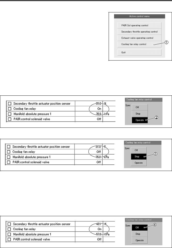
4-104 FI SYSTEM DIAGNOSIS
ACTIVE CONTROL INSPECTION
1)Set up the SDS tool. (Refer to the SDS operation manual for further details.)
2)Start the engine and run it idling condition.
3)Click “Cooling fan relay control” 1.
4) Click the operate button 2.
At this time, if an operation sound is heard from the cooling fan relay and cooling fan motor is operated, the function is normal.
NOTE:
Cooling fan relay and cooling fan motor operation can be checked until the engine coolant temperature is less than 100 °C (212 °F) after starting the engine.
E L P M 5) Click the stop button 3 to check theAoperation properly.
S
6) Click the off button 4 to check the cooling fan relay and cooling fan motor operation.
NOTE:
This inspection should be begun from when the engine coolant temperature is below 50 °C (122 °F). Check that the cooling fan relay operates for a few seconds as the engine coolant temperature arrives each at 50 °C (122 °F), 70 °C (158 °F) and 90 °C (194 °F)/above 4 000 r/min. It is cooling fan motor malfunction or its circuit failure when the motor would not run even if the relay turns to ON.
NOTE:
There is a tolerance of operating temperature of cooling fan relay.